EP2538140A2 - Fixation de chambre de combustion à flux inversé - Google Patents
Fixation de chambre de combustion à flux inversé Download PDFInfo
- Publication number
- EP2538140A2 EP2538140A2 EP12172767A EP12172767A EP2538140A2 EP 2538140 A2 EP2538140 A2 EP 2538140A2 EP 12172767 A EP12172767 A EP 12172767A EP 12172767 A EP12172767 A EP 12172767A EP 2538140 A2 EP2538140 A2 EP 2538140A2
- Authority
- EP
- European Patent Office
- Prior art keywords
- sed
- reverse flow
- flow combustor
- rim
- combustor
- Prior art date
- Legal status (The legal status is an assumption and is not a legal conclusion. Google has not performed a legal analysis and makes no representation as to the accuracy of the status listed.)
- Granted
Links
Images





Classifications
-
- F—MECHANICAL ENGINEERING; LIGHTING; HEATING; WEAPONS; BLASTING
- F23—COMBUSTION APPARATUS; COMBUSTION PROCESSES
- F23R—GENERATING COMBUSTION PRODUCTS OF HIGH PRESSURE OR HIGH VELOCITY, e.g. GAS-TURBINE COMBUSTION CHAMBERS
- F23R3/00—Continuous combustion chambers using liquid or gaseous fuel
- F23R3/42—Continuous combustion chambers using liquid or gaseous fuel characterised by the arrangement or form of the flame tubes or combustion chambers
- F23R3/54—Reverse-flow combustion chambers
-
- F—MECHANICAL ENGINEERING; LIGHTING; HEATING; WEAPONS; BLASTING
- F23—COMBUSTION APPARATUS; COMBUSTION PROCESSES
- F23R—GENERATING COMBUSTION PRODUCTS OF HIGH PRESSURE OR HIGH VELOCITY, e.g. GAS-TURBINE COMBUSTION CHAMBERS
- F23R3/00—Continuous combustion chambers using liquid or gaseous fuel
- F23R3/007—Continuous combustion chambers using liquid or gaseous fuel constructed mainly of ceramic components
-
- F—MECHANICAL ENGINEERING; LIGHTING; HEATING; WEAPONS; BLASTING
- F23—COMBUSTION APPARATUS; COMBUSTION PROCESSES
- F23R—GENERATING COMBUSTION PRODUCTS OF HIGH PRESSURE OR HIGH VELOCITY, e.g. GAS-TURBINE COMBUSTION CHAMBERS
- F23R3/00—Continuous combustion chambers using liquid or gaseous fuel
- F23R3/42—Continuous combustion chambers using liquid or gaseous fuel characterised by the arrangement or form of the flame tubes or combustion chambers
- F23R3/60—Support structures; Attaching or mounting means
Definitions
- the disclosure relates to gas turbine engines. More particularly, the disclosure relates to attaching ceramic matrix composite (CMC) ducts in reverse flow combustors.
- CMC ceramic matrix composite
- Ceramic matrix composite (CMC) materials have been proposed for various uses in high temperature regions of gas turbine engines.
- US Pregrant Publication 2010/0257864 of Prociw et al. discloses use in duct portions of an annular reverse flow combustor.
- the annular reverse flow combustor turns the flow by approximately 180 degrees from an upstream portion of the combustor to the inlet of the turbine section.
- an inlet dome exists at the upstream end of the combustor.
- an outboard portion of the turn is formed by a large exit duct (LED) and an inboard portion of the turn is formed by a small exit duct (SED).
- LED exit duct
- SED small exit duct
- the LED and SED may be formed of CMC.
- the CMC may be secured to adjacent metallic support structure (e.g., engine case structure).
- the SED and LED are alternatively referred to via the same acronyms but different names with various combinations of "short” replacing “small”, “long” replacing “large”, and “entry” replacing “exit” (this last change representing the point of view of the turbine rather than the point of view of the upstream portion of the combustor).
- An outer air inlet ring is positioned between the LED and the OD of the inlet dome.
- An inner air inlet ring is positioned between the SED and the ID of the inlet dome.
- a reverse flow combustor having an inlet end.
- a flowpath extends downstream from the inlet end through a turn. The turn directs the flowpath radially inward and reversing an axial flow direction.
- a large exit duct (LED) is along the turn.
- a small exit duct (SED) is along the turn and joined by a joint to a mounting structure to resist separation in a first axial direction.
- the joint comprises: a first surface on the SED facing partially radially inward; and a mounting feature engaging the first surface.
- the SED may comprise a thickened upstream region.
- the first surface may be a shoulder formed by the thickened upstream region.
- FIG. 1 shows a gas turbine engine 10 generally comprising in serial flow communication from upstream to downstream: a fan 12 through which ambient air is propelled; a multistage compressor 14 for pressurizing the air; an annular reverse flow combustor 16 in which the compressed air is mixed with fuel and ignited for generating an annular stream of hot combustion gases; and a turbine section 18 for extracting energy from the combustion gases.
- axial and radial as used herein are intended to be defined relative to the main central longitudinally extending engine axis 11 (centerline).
- upstream and downstream and intended to be defined relative to the general flow of air and hot combustion gases in the combustor, i.e. from a fuel nozzle end of the combustor where fuel and air are injected for ignition to a combustor exit where the combustion gases exit toward the downstream first turbine stage.
- the annular reverse flow combustor 16 comprises generally an inner combustor liner 17, directly exposed to and facing the combustion chamber 23 defined therewithin.
- the inner liner 17 of the combustor 16 is thus exposed to the highest temperatures, being directly exposed to the combustion chamber 23.
- the inner liner 17 is composed of at least one liner portion that is made of a non-metallic high temperature material such as a ceramic matrix composite (CMC) material.
- CMC ceramic matrix composite
- airflow passages e.g., cooling holes
- the compressed air from the plenum 20 is, in at least this embodiment, fed into the combustion chamber 23 via air holes defined in metallic ring portions 32, 34 (e.g., high temperature nickel-based superalloys with thermal barrier coatings) of the combustor liner, as will be described further below.
- Metered air flow can also be fed into the combustion chamber via the fuel nozzles 30.
- the inner liner 17 extends from an upstream end 21 of the combustor 16 (where a plurality of fuel nozzles 30, which communicate with the combustion chamber 23 to inject fuel therein, are located) to a downstream end (relative to gas flow in the combustion chamber) defining the combustor exit 27.
- the inner liner 17 is, in at least one embodiment, comprised of thee main liner portions, namely a dome portion (inlet dome) 24 at the upstream end (inlet end) 21 of the combustor, and a long exit duct portion 26 and a short exit duct portion 28 which together form the combustor exit 27 at their respective downstream ends.
- Each of the dome portion 24, long exit duct portion 26 and short exit duct portion 28, that are made of the CMC material and which make up a substantial part of the inner liner 17, have a substantially hemi-toroidal shape and constitute an independently formed shell.
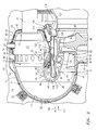
- FIG. 2 shows a rich burn and quick quench combustor where the three CMC components 24, 26, 28 form the inner liner of combustor.
- the disclosure is primarily concerned with the attachment of CMC SED 28.
- CTE coefficients of thermal expansion
- the nature of the dome 24 and the LED 26 make them relatively easy to compliantly mount. In axial/radial section their exterior surfaces (away from the hot gas of the combustor interior) are generally convex. It is thus easy to compliantly compressively hold them in place.
- the exemplary dome and LED are contained within respective shells 40 and 50 with compliant mounting members 42 and 52 respectively engaging the exterior surfaces 44 and 54 of the dome and SED.
- the exemplary shells 40 and 50 are metallic shells mounted to adjacent structure.
- the exemplary spring members 42 are half leaf spring tabs secured to the interior surface of the shell 40.
- the exemplary spring members 52 are more complex assemblies of pistons and coil springs with piston heads engaging the LED exterior surface 54.
- the exemplary dome further includes an interior surface 45, an outboard rim 46, and an inboard rim 47.
- the exemplary liner section 40 also includes an outboard rim 48 and an inboard rim 49.
- the exemplary outboard rim 48 is secured to a mating surface of the outer air inlet ring (outer ring) 34 (e.g., via welding) and the exemplary inboard rim 49 is secured to the inner air inlet ring (inner ring) 32 such as via welding.
- the LED has an interior surface 53, upstream rim 55 and a downstream rim 56.
- the liner 50 includes an upstream portion (e.g., a rim) 57 and a downstream portion (e.g., a flange) 58.
- the exemplary rim 57 is secured to the outer ring 34 (e.g., via welding).
- the exemplary flange 58 is secured to a corresponding flange 60 of the platform ring (inner ring) 61 of an exit vane ring 62.
- the exemplary exit vane ring 62 includes a circumferential array of airfoils 63 extending from the platform 61 to a shroud ring (outer ring) 64.
- the SED extends from an upstream rim 80 to a downstream rim 82 and has a generally convex interior surface 84 and a generally concave exterior surface 86.
- the LED downstream rim 56 and SED downstream rim 82 are proximate respective upstream rims 88 and 90 of the vane inner ring 61 and outer ring 64.
- the first blade stage of the first turbine section is downstream of the vane ring 62 with the blade airfoils 66 shown extending radially outward from a disk 68.
- a leading/upstream portion/region 100 of the SED is shown directed radially inwardly toward the upstream rim 80 (e.g., off-axial by an angle ⁇ 1 ).
- the exemplary SED is of generally constant thickness (e.g., subject to variations in local thickness associated with the imposed curvature of the cross-section of the SED in the vicinity of up to 20%).
- the inward direction of this portion 100 thus creates associated approximately frustoconical surface portions 102 and 104 of the surfaces 84 and 86 along the region 100.
- the surface portion 104 thus faces partially radially inward.
- the surface portion 104 may, thus, be engaged by an associated mounting feature to resist axial separation in a first axial direction 106 (forward in the exemplary engine wherein combustor inlet flow is generally forward). Movement in a second direction 107 opposite 106 is resisted by engagement of the surface portion 102 with a corresponding angled downstream surface 108 of the ring 32 (e.g., also at ⁇ 1 ). Exemplary ⁇ 1 are 20-60°, more narrowly, 30-50° or 35-45°).
- the SED may be retained against outward radial movement/displacement by engagement of the surface portion 102 with the downstream surface 108 and/or by hoop stress in the CMC.
- An exemplary SED is formed of CMCs such as silicon carbide reinforced silicon carbide (SiC/SiC) or silicon (Si) melt infiltrated SiC/SiC (MI SiC/SiC).
- the CMC may be a substrate atop which there are one or more protective coating layers or adhered/secured to which there are additional structures. It may be formed with a sock weave fiber reinforcement including continuous hoop fibers.
- the exemplary mounting feature comprises a circumferential array of radially outwardly-projecting distal tabs 110 of a metallic clamp ring 112.
- the clamp ring is pulled axially in the direction 107 via an annular array of hook bolt assemblies 114.
- Exemplary hook bolt assemblies 114 are mounted to the dome shell 40.
- Exemplary hook bolt assemblies include a fixed base (support) 120 mounted to an inboard portion of the dome shell.
- a threaded shaft 122 extends through an aperture in the base 120 and is engaged by a nut 124 which may be turned (tightened) to draw the shaft at least partially axially in the direction 107.
- the shaft is coupled to a hook 126 (see also, FIG.
- the gripping of the portion 100 is the only mounting of the SED with the downstream rim 82 being slightly spaced apart from adjacent structures.
- Rotational registration and retention of the SED to the ring 32 may also be provided.
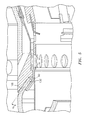
- Exemplary rotational registration and retention means comprises a circumferential series of recesses 140 ( FIG. 4 ) in the rim 80 and region 100. These recesses 140 cooperate with protruding portions 142 of the ring 32 (e.g., protruding from the main frustoconical portion of the surface 108).
- the exemplary recesses are through-recesses extending all the way between the surfaces 102 and 104.
- the recesses 140 and protruding portions 142 may be reversed with recesses appearing in the ring and protruding portions appearing on the SED.
- FIG. 5 shows an otherwise similar system with hooks penetrating the ring from outboard to inboard (in distinction to inboard-to-outboard).
- FIGS. 6 and 7 show mounting features comprising circumferential straps 200.
- Each strap extends from a first circumferential end 202 ( FIG. 7 ) to a second circumferential end 204.
- the exemplary straps are fastened to the inner ring 32 and capture the SED.
- the exemplary implementation is based upon the SED and ring configuration of the FIG. 2 embodiment with each strap fastened between two adjacent ones of the protrusions 142 (e.g., via screws 210 extending into threaded bores 212 in the protrusions 142).
- Each exemplary strap 200 thus has a first surface 220 and a second surface 222.
- the first surface 220 engages the associated protrusions 142 and is held spaced-apart from the remainder of the surface 108 so that intact portions of the region 100 between the recesses 140 in the SED are captured between the surface 220 and the surface 108.
- Springs such as Bellville washers 230 can be introduced with the bolts to maintain a constant clamp load.
- FIG. 8 shows an alternative configuration wherein a leading portion 300 of the SED 301 is relatively thickened compared with a remaining portion 302 (e.g., along the portion 300 the thickness T is at least 150%, more narrowly, 150-250% or 175-225% the thickness along the portion 302).
- the leading portion extends generally axially to a leading/upstream rim 303.
- a portion 310 of the exterior surface transitions and thus is directed partially radially inward and partially in the direction 106 (e.g., at an angle ⁇ 2 which may be the same size as ⁇ 1 ).
- An annular resilient member 312 is captured between this surface and a corresponding surface portion 314 of a liner 316.
- the liner extends from an upstream rim/end 318 which is secured to the inner ring 306.
- the surface portion 314 faces partially radially outward and partially opposite the direction 106 to allow capturing of the member 312.
- An exemplary member 312 is a metallic generally C-sectioned sheetmetal member such as is used as a seal.
- the exemplary member 312 is a U seal or an Omega seal which compresses to transmit force in both the radial and axial directions.
- Other types of springs such as canted coil springs can also be employed.
- the SED 301 may be installed by a process comprising: 1) sliding the U seal 312 onto the metal baffle plate 316; 2) cooling the assembly of the seal 312 and plate 316 to thermally contract them (e.g., to -40C); 3) heating the CMC SED 301 to expand it (e.g., to 1000C); 4) sliding/inserting the cooled assembly of seal 312 and plate 316 into the heated CMC SED 301; and 5) welding the baffle plate 316 to inner air inlet ring 306.
- the SED is at a hotter-than-ambient temperature and the assembly is at a cooler-than-ambient temperature
- FIG. 9 shows an alternate configuration of a similar SED with a resilient member 400 replacing the member 312.
Landscapes
- Engineering & Computer Science (AREA)
- Chemical & Material Sciences (AREA)
- Combustion & Propulsion (AREA)
- Mechanical Engineering (AREA)
- General Engineering & Computer Science (AREA)
- Ceramic Engineering (AREA)
- Turbine Rotor Nozzle Sealing (AREA)
- Quick-Acting Or Multi-Walled Pipe Joints (AREA)
Applications Claiming Priority (1)
| Application Number | Priority Date | Filing Date | Title |
|---|---|---|---|
| US13/167,167 US8864492B2 (en) | 2011-06-23 | 2011-06-23 | Reverse flow combustor duct attachment |
Publications (3)
| Publication Number | Publication Date |
|---|---|
| EP2538140A2 true EP2538140A2 (fr) | 2012-12-26 |
| EP2538140A3 EP2538140A3 (fr) | 2014-01-15 |
| EP2538140B1 EP2538140B1 (fr) | 2018-06-13 |
Family
ID=46319026
Family Applications (1)
| Application Number | Title | Priority Date | Filing Date |
|---|---|---|---|
| EP12172767.1A Active EP2538140B1 (fr) | 2011-06-23 | 2012-06-20 | Fixation de chambre de combustion à flux inversé |
Country Status (2)
| Country | Link |
|---|---|
| US (1) | US8864492B2 (fr) |
| EP (1) | EP2538140B1 (fr) |
Cited By (6)
| Publication number | Priority date | Publication date | Assignee | Title |
|---|---|---|---|---|
| WO2014004017A1 (fr) * | 2012-06-30 | 2014-01-03 | General Electric Company | Composant composite de matrice céramique et procédé d'attache d'un joint statique à un composant composite de matrice céramique |
| WO2014207207A1 (fr) * | 2013-06-27 | 2014-12-31 | Siemens Aktiengesellschaft | Fixation d'une brique de protection thermique sur une structure porteuse et protection thermique |
| EP3211310A1 (fr) * | 2016-02-25 | 2017-08-30 | General Electric Company | Ensemble de chambre de combustion |
| EP3211317A1 (fr) * | 2016-02-25 | 2017-08-30 | General Electric Company | Ensemble de chambre de combustion |
| EP3640544A1 (fr) * | 2018-10-15 | 2020-04-22 | United Technologies Corporation | Ensemble de fixation de chemise de chambre de combustion pour moteur à turbine à gaz |
| EP3640543A1 (fr) * | 2018-10-15 | 2020-04-22 | United Technologies Corporation | Ensemble de fixation de chemise de chambre de combustion pour moteur à turbine à gaz |
Families Citing this family (15)
| Publication number | Priority date | Publication date | Assignee | Title |
|---|---|---|---|---|
| US8745989B2 (en) * | 2009-04-09 | 2014-06-10 | Pratt & Whitney Canada Corp. | Reverse flow ceramic matrix composite combustor |
| WO2015017084A1 (fr) * | 2013-07-30 | 2015-02-05 | Clearsign Combustion Corporation | Chambre de combustion pourvue d'un corps non métallique présentant des électrodes externes |
| US10429070B2 (en) * | 2016-02-25 | 2019-10-01 | General Electric Company | Combustor assembly |
| US10928069B2 (en) * | 2016-06-17 | 2021-02-23 | Pratt & Whitney Canada Corp. | Small exit duct for a reverse flow combustor with integrated fastening elements |
| US10690345B2 (en) | 2016-07-06 | 2020-06-23 | General Electric Company | Combustor assemblies for use in turbine engines and methods of assembling same |
| US10358922B2 (en) | 2016-11-10 | 2019-07-23 | Rolls-Royce Corporation | Turbine wheel with circumferentially-installed inter-blade heat shields |
| US10823418B2 (en) * | 2017-03-02 | 2020-11-03 | General Electric Company | Gas turbine engine combustor comprising air inlet tubes arranged around the combustor |
| CN107120689B (zh) * | 2017-04-28 | 2019-04-26 | 中国航发湖南动力机械研究所 | 回流燃烧室内弯管结构及回流燃烧室、燃气涡轮发动机 |
| US10976052B2 (en) | 2017-10-25 | 2021-04-13 | General Electric Company | Volute trapped vortex combustor assembly |
| US10976053B2 (en) | 2017-10-25 | 2021-04-13 | General Electric Company | Involute trapped vortex combustor assembly |
| US11112119B2 (en) * | 2018-10-25 | 2021-09-07 | General Electric Company | Combustor assembly for a turbo machine |
| US11181269B2 (en) | 2018-11-15 | 2021-11-23 | General Electric Company | Involute trapped vortex combustor assembly |
| US11435078B2 (en) * | 2018-12-20 | 2022-09-06 | Pratt & Whitney Canada Corp. | Stand-off device for double-skin combustor liner |
| US11698192B2 (en) | 2021-04-06 | 2023-07-11 | Raytheon Technologies Corporation | CMC combustor panel attachment arrangement |
| US11543130B1 (en) * | 2021-06-28 | 2023-01-03 | Collins Engine Nozzles, Inc. | Passive secondary air assist nozzles |
Citations (1)
| Publication number | Priority date | Publication date | Assignee | Title |
|---|---|---|---|---|
| US20100257864A1 (en) | 2009-04-09 | 2010-10-14 | Pratt & Whitney Canada Corp. | Reverse flow ceramic matrix composite combustor |
Family Cites Families (105)
| Publication number | Priority date | Publication date | Assignee | Title |
|---|---|---|---|---|
| US3691766A (en) * | 1970-12-16 | 1972-09-19 | Rolls Royce | Combustion chambers |
| US3745766A (en) * | 1971-10-26 | 1973-07-17 | Avco Corp | Variable geometry for controlling the flow of air to a combustor |
| GB1424197A (en) * | 1972-06-09 | 1976-02-11 | Lucas Industries Ltd | Combustion chambers for gas turbine engines |
| US3887299A (en) | 1973-08-28 | 1975-06-03 | Us Air Force | Non-abradable turbine seal |
| US3952504A (en) | 1973-12-14 | 1976-04-27 | Joseph Lucas (Industries) Limited | Flame tubes |
| US4008978A (en) | 1976-03-19 | 1977-02-22 | General Motors Corporation | Ceramic turbine structures |
| DE2617024C2 (de) * | 1976-04-17 | 1985-09-26 | MTU Motoren- und Turbinen-Union München GmbH, 8000 München | Gasturbinentriebwerk |
| US4411594A (en) * | 1979-06-30 | 1983-10-25 | Rolls-Royce Limited | Support member and a component supported thereby |
| US4363208A (en) | 1980-11-10 | 1982-12-14 | General Motors Corporation | Ceramic combustor mounting |
| US4398866A (en) | 1981-06-24 | 1983-08-16 | Avco Corporation | Composite ceramic/metal cylinder for gas turbine engine |
| US4549402A (en) * | 1982-05-26 | 1985-10-29 | Pratt & Whitney Aircraft Of Canada Limited | Combustor for a gas turbine engine |
| US4594848A (en) * | 1982-07-22 | 1986-06-17 | The Garrett Corporation | Gas turbine combustor operating method |
| US4626461A (en) | 1983-01-18 | 1986-12-02 | United Technologies Corporation | Gas turbine engine and composite parts |
| US4573320A (en) | 1985-05-03 | 1986-03-04 | Mechanical Technology Incorporated | Combustion system |
| FR2597921A1 (fr) | 1986-04-24 | 1987-10-30 | Snecma | Anneau de turbine sectorise |
| DE3738439C1 (de) * | 1987-11-12 | 1989-03-09 | Mtu Muenchen Gmbh | Leitkranz fuer eine Gasturbine |
| GB8903000D0 (en) | 1989-02-10 | 1989-03-30 | Rolls Royce Plc | A blade tip clearance control arrangement for a gas turbine engine |
| GB2250782B (en) | 1990-12-11 | 1994-04-27 | Rolls Royce Plc | Stator vane assembly |
| US5299914A (en) | 1991-09-11 | 1994-04-05 | General Electric Company | Staggered fan blade assembly for a turbofan engine |
| US5237813A (en) * | 1992-08-21 | 1993-08-24 | Allied-Signal Inc. | Annular combustor with outer transition liner cooling |
| EP0700498B1 (fr) * | 1993-06-01 | 1998-10-21 | Pratt & Whitney Canada, Inc. | Injecteur radial de carburant, a entrainement d'air |
| FR2708311B1 (fr) | 1993-07-28 | 1995-09-01 | Snecma | Stator de turbomachine à aubes pivotantes et anneau de commande. |
| US5392596A (en) | 1993-12-21 | 1995-02-28 | Solar Turbines Incorporated | Combustor assembly construction |
| US6042315A (en) | 1997-10-06 | 2000-03-28 | United Technologies Corporation | Fastener |
| US6045310A (en) | 1997-10-06 | 2000-04-04 | United Technologies Corporation | Composite fastener for use in high temperature environments |
| US6197424B1 (en) | 1998-03-27 | 2001-03-06 | Siemens Westinghouse Power Corporation | Use of high temperature insulation for ceramic matrix composites in gas turbines |
| US6182436B1 (en) * | 1998-07-09 | 2001-02-06 | Pratt & Whitney Canada Corp. | Porus material torch igniter |
| US6250883B1 (en) | 1999-04-13 | 2001-06-26 | Alliedsignal Inc. | Integral ceramic blisk assembly |
| US6269628B1 (en) * | 1999-06-10 | 2001-08-07 | Pratt & Whitney Canada Corp. | Apparatus for reducing combustor exit duct cooling |
| US6241471B1 (en) | 1999-08-26 | 2001-06-05 | General Electric Co. | Turbine bucket tip shroud reinforcement |
| US6200092B1 (en) | 1999-09-24 | 2001-03-13 | General Electric Company | Ceramic turbine nozzle |
| US6451416B1 (en) | 1999-11-19 | 2002-09-17 | United Technologies Corporation | Hybrid monolithic ceramic and ceramic matrix composite airfoil and method for making the same |
| US6325593B1 (en) | 2000-02-18 | 2001-12-04 | General Electric Company | Ceramic turbine airfoils with cooled trailing edge blocks |
| US6397603B1 (en) | 2000-05-05 | 2002-06-04 | The United States Of America As Represented By The Secretary Of The Air Force | Conbustor having a ceramic matrix composite liner |
| US6514046B1 (en) | 2000-09-29 | 2003-02-04 | Siemens Westinghouse Power Corporation | Ceramic composite vane with metallic substructure |
| FR2817192B1 (fr) | 2000-11-28 | 2003-08-08 | Snecma Moteurs | Ensemble forme par au moins une pale et une plate-forme de fixation de la pale, pour une turbomachine, et procede pour sa fabrication |
| ITTO20010346A1 (it) * | 2001-04-10 | 2002-10-10 | Fiatavio Spa | Combustore per una turbina a gas, particolarmente per un motore aeronautico. |
| US6758386B2 (en) | 2001-09-18 | 2004-07-06 | The Boeing Company | Method of joining ceramic matrix composites and metals |
| US6746755B2 (en) | 2001-09-24 | 2004-06-08 | Siemens Westinghouse Power Corporation | Ceramic matrix composite structure having integral cooling passages and method of manufacture |
| US6733233B2 (en) * | 2002-04-26 | 2004-05-11 | Pratt & Whitney Canada Corp. | Attachment of a ceramic shroud in a metal housing |
| US6709230B2 (en) | 2002-05-31 | 2004-03-23 | Siemens Westinghouse Power Corporation | Ceramic matrix composite gas turbine vane |
| US6648597B1 (en) | 2002-05-31 | 2003-11-18 | Siemens Westinghouse Power Corporation | Ceramic matrix composite turbine vane |
| US6935836B2 (en) | 2002-06-05 | 2005-08-30 | Allison Advanced Development Company | Compressor casing with passive tip clearance control and endwall ovalization control |
| JP3840556B2 (ja) | 2002-08-22 | 2006-11-01 | 川崎重工業株式会社 | 燃焼器ライナのシール構造 |
| US6758653B2 (en) | 2002-09-09 | 2004-07-06 | Siemens Westinghouse Power Corporation | Ceramic matrix composite component for a gas turbine engine |
| US7093359B2 (en) | 2002-09-17 | 2006-08-22 | Siemens Westinghouse Power Corporation | Composite structure formed by CMC-on-insulation process |
| US9068464B2 (en) | 2002-09-17 | 2015-06-30 | Siemens Energy, Inc. | Method of joining ceramic parts and articles so formed |
| EP1413831A1 (fr) * | 2002-10-21 | 2004-04-28 | Siemens Aktiengesellschaft | Chambre de combustion annulaire pour turbine à gaz et turbine à gaz |
| US7234304B2 (en) * | 2002-10-23 | 2007-06-26 | Pratt & Whitney Canada Corp | Aerodynamic trip to improve acoustic transmission loss and reduce noise level for gas turbine engine |
| US6925810B2 (en) * | 2002-11-08 | 2005-08-09 | Honeywell International, Inc. | Gas turbine engine transition liner assembly and repair |
| US7094027B2 (en) | 2002-11-27 | 2006-08-22 | General Electric Company | Row of long and short chord length and high and low temperature capability turbine airfoils |
| US6910853B2 (en) | 2002-11-27 | 2005-06-28 | General Electric Company | Structures for attaching or sealing a space between components having different coefficients or rates of thermal expansion |
| US6893214B2 (en) | 2002-12-20 | 2005-05-17 | General Electric Company | Shroud segment and assembly with surface recessed seal bridging adjacent members |
| US6808363B2 (en) | 2002-12-20 | 2004-10-26 | General Electric Company | Shroud segment and assembly with circumferential seal at a planar segment surface |
| US6711900B1 (en) * | 2003-02-04 | 2004-03-30 | Pratt & Whitney Canada Corp. | Combustor liner V-band design |
| GB2402717B (en) | 2003-06-10 | 2006-05-10 | Rolls Royce Plc | A vane assembly for a gas turbine engine |
| US7134287B2 (en) * | 2003-07-10 | 2006-11-14 | General Electric Company | Turbine combustor endcover assembly |
| US6942203B2 (en) | 2003-11-04 | 2005-09-13 | General Electric Company | Spring mass damper system for turbine shrouds |
| GB0326544D0 (en) | 2003-11-14 | 2003-12-17 | Rolls Royce Plc | Variable stator vane arrangement for a compressor |
| US20050158171A1 (en) | 2004-01-15 | 2005-07-21 | General Electric Company | Hybrid ceramic matrix composite turbine blades for improved processibility and performance |
| US7090459B2 (en) | 2004-03-31 | 2006-08-15 | General Electric Company | Hybrid seal and system and method incorporating the same |
| US7269958B2 (en) * | 2004-09-10 | 2007-09-18 | Pratt & Whitney Canada Corp. | Combustor exit duct |
| US7198458B2 (en) | 2004-12-02 | 2007-04-03 | Siemens Power Generation, Inc. | Fail safe cooling system for turbine vanes |
| US7247003B2 (en) | 2004-12-02 | 2007-07-24 | Siemens Power Generation, Inc. | Stacked lamellate assembly |
| US7153096B2 (en) | 2004-12-02 | 2006-12-26 | Siemens Power Generation, Inc. | Stacked laminate CMC turbine vane |
| GB0428368D0 (en) | 2004-12-24 | 2005-02-02 | Rolls Royce Plc | A composite blade |
| US7435058B2 (en) | 2005-01-18 | 2008-10-14 | Siemens Power Generation, Inc. | Ceramic matrix composite vane with chordwise stiffener |
| US8137611B2 (en) | 2005-03-17 | 2012-03-20 | Siemens Energy, Inc. | Processing method for solid core ceramic matrix composite airfoil |
| US7452182B2 (en) | 2005-04-07 | 2008-11-18 | Siemens Energy, Inc. | Multi-piece turbine vane assembly |
| US7647779B2 (en) | 2005-04-27 | 2010-01-19 | United Technologies Corporation | Compliant metal support for ceramic combustor liner in a gas turbine engine |
| US7278830B2 (en) | 2005-05-18 | 2007-10-09 | Allison Advanced Development Company, Inc. | Composite filled gas turbine engine blade with gas film damper |
| GB2427658B (en) | 2005-06-30 | 2007-08-22 | Rolls Royce Plc | Organic matrix composite integrally bladed rotor |
| US7785076B2 (en) | 2005-08-30 | 2010-08-31 | Siemens Energy, Inc. | Refractory component with ceramic matrix composite skeleton |
| US7546743B2 (en) | 2005-10-12 | 2009-06-16 | General Electric Company | Bolting configuration for joining ceramic combustor liner to metal mounting attachments |
| US7600970B2 (en) | 2005-12-08 | 2009-10-13 | General Electric Company | Ceramic matrix composite vane seals |
| US7510379B2 (en) | 2005-12-22 | 2009-03-31 | General Electric Company | Composite blading member and method for making |
| US7648336B2 (en) | 2006-01-03 | 2010-01-19 | General Electric Company | Apparatus and method for assembling a gas turbine stator |
| FR2896854B1 (fr) * | 2006-02-01 | 2008-04-25 | Snecma Sa | Procede de fabrication d'une chambre de combustion |
| US7624577B2 (en) * | 2006-03-31 | 2009-12-01 | Pratt & Whitney Canada Corp. | Gas turbine engine combustor with improved cooling |
| US7950233B2 (en) * | 2006-03-31 | 2011-05-31 | Pratt & Whitney Canada Corp. | Combustor |
| US20070245710A1 (en) * | 2006-04-21 | 2007-10-25 | Honeywell International, Inc. | Optimized configuration of a reverse flow combustion system for a gas turbine engine |
| US7452189B2 (en) | 2006-05-03 | 2008-11-18 | United Technologies Corporation | Ceramic matrix composite turbine engine vane |
| US7534086B2 (en) | 2006-05-05 | 2009-05-19 | Siemens Energy, Inc. | Multi-layer ring seal |
| US7726936B2 (en) | 2006-07-25 | 2010-06-01 | Siemens Energy, Inc. | Turbine engine ring seal |
| US7488157B2 (en) | 2006-07-27 | 2009-02-10 | Siemens Energy, Inc. | Turbine vane with removable platform inserts |
| US7497662B2 (en) | 2006-07-31 | 2009-03-03 | General Electric Company | Methods and systems for assembling rotatable machines |
| US8141370B2 (en) | 2006-08-08 | 2012-03-27 | General Electric Company | Methods and apparatus for radially compliant component mounting |
| US7665960B2 (en) | 2006-08-10 | 2010-02-23 | United Technologies Corporation | Turbine shroud thermal distortion control |
| US7771160B2 (en) * | 2006-08-10 | 2010-08-10 | United Technologies Corporation | Ceramic shroud assembly |
| US7836702B2 (en) * | 2006-09-15 | 2010-11-23 | Pratt & Whitney Canada Corp. | Gas turbine combustor exit duct and HP vane interface |
| US7753643B2 (en) | 2006-09-22 | 2010-07-13 | Siemens Energy, Inc. | Stacked laminate bolted ring segment |
| US7762768B2 (en) | 2006-11-13 | 2010-07-27 | United Technologies Corporation | Mechanical support of a ceramic gas turbine vane ring |
| FR2913717A1 (fr) | 2007-03-15 | 2008-09-19 | Snecma Propulsion Solide Sa | Ensemble d'anneau de turbine pour turbine a gaz |
| US7824152B2 (en) | 2007-05-09 | 2010-11-02 | Siemens Energy, Inc. | Multivane segment mounting arrangement for a gas turbine |
| US8210803B2 (en) | 2007-06-28 | 2012-07-03 | United Technologies Corporation | Ceramic matrix composite turbine engine vane |
| US7954326B2 (en) * | 2007-11-28 | 2011-06-07 | Honeywell International Inc. | Systems and methods for cooling gas turbine engine transition liners |
| US8438855B2 (en) * | 2008-07-24 | 2013-05-14 | General Electric Company | Slotted compressor diffuser and related method |
| US8226360B2 (en) * | 2008-10-31 | 2012-07-24 | General Electric Company | Crenelated turbine nozzle |
| US8714932B2 (en) | 2008-12-31 | 2014-05-06 | General Electric Company | Ceramic matrix composite blade having integral platform structures and methods of fabrication |
| US8534995B2 (en) | 2009-03-05 | 2013-09-17 | United Technologies Corporation | Turbine engine sealing arrangement |
| JP5384983B2 (ja) * | 2009-03-27 | 2014-01-08 | 本田技研工業株式会社 | タービンシュラウド |
| FR2946999B1 (fr) | 2009-06-18 | 2019-08-09 | Safran Aircraft Engines | Element de distributeur de turbine en cmc, procede pour sa fabrication, et distributeur et turbine a gaz l'incorporant. |
| US8206096B2 (en) * | 2009-07-08 | 2012-06-26 | General Electric Company | Composite turbine nozzle |
| US8167546B2 (en) | 2009-09-01 | 2012-05-01 | United Technologies Corporation | Ceramic turbine shroud support |
| US8739547B2 (en) * | 2011-06-23 | 2014-06-03 | United Technologies Corporation | Gas turbine engine joint having a metallic member, a CMC member, and a ceramic key |
-
2011
- 2011-06-23 US US13/167,167 patent/US8864492B2/en active Active
-
2012
- 2012-06-20 EP EP12172767.1A patent/EP2538140B1/fr active Active
Patent Citations (1)
| Publication number | Priority date | Publication date | Assignee | Title |
|---|---|---|---|---|
| US20100257864A1 (en) | 2009-04-09 | 2010-10-14 | Pratt & Whitney Canada Corp. | Reverse flow ceramic matrix composite combustor |
Cited By (12)
| Publication number | Priority date | Publication date | Assignee | Title |
|---|---|---|---|---|
| WO2014004017A1 (fr) * | 2012-06-30 | 2014-01-03 | General Electric Company | Composant composite de matrice céramique et procédé d'attache d'un joint statique à un composant composite de matrice céramique |
| WO2014207207A1 (fr) * | 2013-06-27 | 2014-12-31 | Siemens Aktiengesellschaft | Fixation d'une brique de protection thermique sur une structure porteuse et protection thermique |
| US10330318B2 (en) | 2013-06-27 | 2019-06-25 | Siemens Aktiengesellschaft | Securing a heat shield block to a support structure, and heat shield |
| EP3211310A1 (fr) * | 2016-02-25 | 2017-08-30 | General Electric Company | Ensemble de chambre de combustion |
| EP3211317A1 (fr) * | 2016-02-25 | 2017-08-30 | General Electric Company | Ensemble de chambre de combustion |
| US10222065B2 (en) | 2016-02-25 | 2019-03-05 | General Electric Company | Combustor assembly for a gas turbine engine |
| US10228136B2 (en) | 2016-02-25 | 2019-03-12 | General Electric Company | Combustor assembly |
| EP3640544A1 (fr) * | 2018-10-15 | 2020-04-22 | United Technologies Corporation | Ensemble de fixation de chemise de chambre de combustion pour moteur à turbine à gaz |
| EP3640543A1 (fr) * | 2018-10-15 | 2020-04-22 | United Technologies Corporation | Ensemble de fixation de chemise de chambre de combustion pour moteur à turbine à gaz |
| US11255547B2 (en) | 2018-10-15 | 2022-02-22 | Raytheon Technologies Corporation | Combustor liner attachment assembly for gas turbine engine |
| US11293637B2 (en) | 2018-10-15 | 2022-04-05 | Raytheon Technologies Corporation | Combustor liner attachment assembly for gas turbine engine |
| EP4414607A3 (fr) * | 2018-10-15 | 2024-10-30 | RTX Corporation | Ensemble de fixation de chemise de chambre de combustion pour moteur à turbine à gaz |
Also Published As
| Publication number | Publication date |
|---|---|
| EP2538140A3 (fr) | 2014-01-15 |
| US20120328996A1 (en) | 2012-12-27 |
| EP2538140B1 (fr) | 2018-06-13 |
| US8864492B2 (en) | 2014-10-21 |
Similar Documents
| Publication | Publication Date | Title |
|---|---|---|
| EP2538140B1 (fr) | Fixation de chambre de combustion à flux inversé | |
| EP2538141B1 (fr) | Chambre de combustion retournement | |
| US8141370B2 (en) | Methods and apparatus for radially compliant component mounting | |
| US8424312B2 (en) | Exhaust system for gas turbine | |
| US6895761B2 (en) | Mounting assembly for the aft end of a ceramic matrix composite liner in a gas turbine engine combustor | |
| US11466855B2 (en) | Gas turbine engine combustor with ceramic matrix composite liner | |
| EP2239436A2 (fr) | Chambre de combustion composite à matrice céramique à flux inverse | |
| US11428410B2 (en) | Combustor for a gas turbine engine with ceramic matrix composite heat shield and seal retainer | |
| EP3730739B1 (fr) | Ensemble de turbine pour un moteur à turbine à gaz comprenant une aube composite à matrice céramique | |
| EP3270061B1 (fr) | Montage de segments d'un revêtement d'une chambre de combustion | |
| CN115949968B (zh) | 燃烧器旋流器到伪圆顶附接以及与cmc圆顶接口 | |
| US11466858B2 (en) | Combustor for a gas turbine engine with ceramic matrix composite sealing element | |
| US11193393B2 (en) | Turbine section assembly with ceramic matrix composite vane | |
| EP3730738B1 (fr) | Ensemble de turbine pour un moteur à turbine à gaz comprenant une aube composite à matrice céramique | |
| JP7271232B2 (ja) | 環状燃焼器ライナの遷移ゾーン用の内側冷却シュラウド | |
| US11402100B2 (en) | Ring assembly for double-skin combustor liner | |
| US12298006B1 (en) | Combustor including a heat shield for a turbine engine | |
| US12372238B1 (en) | Gas turbine engine combustor having a ceramic matrix composite liner and dome | |
| WO2019240754A2 (fr) | Aube céramique et métallique composite pour turbine à combustion |
Legal Events
| Date | Code | Title | Description |
|---|---|---|---|
| PUAI | Public reference made under article 153(3) epc to a published international application that has entered the european phase |
Free format text: ORIGINAL CODE: 0009012 |
|
| AK | Designated contracting states |
Kind code of ref document: A2 Designated state(s): AL AT BE BG CH CY CZ DE DK EE ES FI FR GB GR HR HU IE IS IT LI LT LU LV MC MK MT NL NO PL PT RO RS SE SI SK SM TR |
|
| AX | Request for extension of the european patent |
Extension state: BA ME |
|
| PUAL | Search report despatched |
Free format text: ORIGINAL CODE: 0009013 |
|
| AK | Designated contracting states |
Kind code of ref document: A3 Designated state(s): AL AT BE BG CH CY CZ DE DK EE ES FI FR GB GR HR HU IE IS IT LI LT LU LV MC MK MT NL NO PL PT RO RS SE SI SK SM TR |
|
| AX | Request for extension of the european patent |
Extension state: BA ME |
|
| RIC1 | Information provided on ipc code assigned before grant |
Ipc: F23R 3/60 20060101ALI20131210BHEP Ipc: F23R 3/54 20060101AFI20131210BHEP Ipc: F23R 3/00 20060101ALI20131210BHEP |
|
| 17P | Request for examination filed |
Effective date: 20140626 |
|
| RBV | Designated contracting states (corrected) |
Designated state(s): AL AT BE BG CH CY CZ DE DK EE ES FI FR GB GR HR HU IE IS IT LI LT LU LV MC MK MT NL NO PL PT RO RS SE SI SK SM TR |
|
| RAP1 | Party data changed (applicant data changed or rights of an application transferred) |
Owner name: PRATT & WHITNEY CANADA CORP. Owner name: UNITED TECHNOLOGIES CORPORATION |
|
| STAA | Information on the status of an ep patent application or granted ep patent |
Free format text: STATUS: EXAMINATION IS IN PROGRESS |
|
| 17Q | First examination report despatched |
Effective date: 20170210 |
|
| GRAP | Despatch of communication of intention to grant a patent |
Free format text: ORIGINAL CODE: EPIDOSNIGR1 |
|
| STAA | Information on the status of an ep patent application or granted ep patent |
Free format text: STATUS: GRANT OF PATENT IS INTENDED |
|
| INTG | Intention to grant announced |
Effective date: 20180103 |
|
| GRAS | Grant fee paid |
Free format text: ORIGINAL CODE: EPIDOSNIGR3 |
|
| GRAA | (expected) grant |
Free format text: ORIGINAL CODE: 0009210 |
|
| STAA | Information on the status of an ep patent application or granted ep patent |
Free format text: STATUS: THE PATENT HAS BEEN GRANTED |
|
| AK | Designated contracting states |
Kind code of ref document: B1 Designated state(s): AL AT BE BG CH CY CZ DE DK EE ES FI FR GB GR HR HU IE IS IT LI LT LU LV MC MK MT NL NO PL PT RO RS SE SI SK SM TR |
|
| REG | Reference to a national code |
Ref country code: GB Ref legal event code: FG4D |
|
| REG | Reference to a national code |
Ref country code: CH Ref legal event code: EP Ref country code: AT Ref legal event code: REF Ref document number: 1008887 Country of ref document: AT Kind code of ref document: T Effective date: 20180615 |
|
| REG | Reference to a national code |
Ref country code: IE Ref legal event code: FG4D |
|
| REG | Reference to a national code |
Ref country code: DE Ref legal event code: R096 Ref document number: 602012047360 Country of ref document: DE |
|
| REG | Reference to a national code |
Ref country code: FR Ref legal event code: PLFP Year of fee payment: 7 |
|
| REG | Reference to a national code |
Ref country code: NL Ref legal event code: MP Effective date: 20180613 |
|
| REG | Reference to a national code |
Ref country code: LT Ref legal event code: MG4D |
|
| PG25 | Lapsed in a contracting state [announced via postgrant information from national office to epo] |
Ref country code: BG Free format text: LAPSE BECAUSE OF FAILURE TO SUBMIT A TRANSLATION OF THE DESCRIPTION OR TO PAY THE FEE WITHIN THE PRESCRIBED TIME-LIMIT Effective date: 20180913 Ref country code: NO Free format text: LAPSE BECAUSE OF FAILURE TO SUBMIT A TRANSLATION OF THE DESCRIPTION OR TO PAY THE FEE WITHIN THE PRESCRIBED TIME-LIMIT Effective date: 20180913 Ref country code: FI Free format text: LAPSE BECAUSE OF FAILURE TO SUBMIT A TRANSLATION OF THE DESCRIPTION OR TO PAY THE FEE WITHIN THE PRESCRIBED TIME-LIMIT Effective date: 20180613 Ref country code: CY Free format text: LAPSE BECAUSE OF FAILURE TO SUBMIT A TRANSLATION OF THE DESCRIPTION OR TO PAY THE FEE WITHIN THE PRESCRIBED TIME-LIMIT Effective date: 20180613 Ref country code: ES Free format text: LAPSE BECAUSE OF FAILURE TO SUBMIT A TRANSLATION OF THE DESCRIPTION OR TO PAY THE FEE WITHIN THE PRESCRIBED TIME-LIMIT Effective date: 20180613 Ref country code: SE Free format text: LAPSE BECAUSE OF FAILURE TO SUBMIT A TRANSLATION OF THE DESCRIPTION OR TO PAY THE FEE WITHIN THE PRESCRIBED TIME-LIMIT Effective date: 20180613 Ref country code: LT Free format text: LAPSE BECAUSE OF FAILURE TO SUBMIT A TRANSLATION OF THE DESCRIPTION OR TO PAY THE FEE WITHIN THE PRESCRIBED TIME-LIMIT Effective date: 20180613 |
|
| PG25 | Lapsed in a contracting state [announced via postgrant information from national office to epo] |
Ref country code: LV Free format text: LAPSE BECAUSE OF FAILURE TO SUBMIT A TRANSLATION OF THE DESCRIPTION OR TO PAY THE FEE WITHIN THE PRESCRIBED TIME-LIMIT Effective date: 20180613 Ref country code: GR Free format text: LAPSE BECAUSE OF FAILURE TO SUBMIT A TRANSLATION OF THE DESCRIPTION OR TO PAY THE FEE WITHIN THE PRESCRIBED TIME-LIMIT Effective date: 20180914 Ref country code: HR Free format text: LAPSE BECAUSE OF FAILURE TO SUBMIT A TRANSLATION OF THE DESCRIPTION OR TO PAY THE FEE WITHIN THE PRESCRIBED TIME-LIMIT Effective date: 20180613 Ref country code: RS Free format text: LAPSE BECAUSE OF FAILURE TO SUBMIT A TRANSLATION OF THE DESCRIPTION OR TO PAY THE FEE WITHIN THE PRESCRIBED TIME-LIMIT Effective date: 20180613 |
|
| REG | Reference to a national code |
Ref country code: AT Ref legal event code: MK05 Ref document number: 1008887 Country of ref document: AT Kind code of ref document: T Effective date: 20180613 |
|
| PG25 | Lapsed in a contracting state [announced via postgrant information from national office to epo] |
Ref country code: NL Free format text: LAPSE BECAUSE OF FAILURE TO SUBMIT A TRANSLATION OF THE DESCRIPTION OR TO PAY THE FEE WITHIN THE PRESCRIBED TIME-LIMIT Effective date: 20180613 |
|
| PG25 | Lapsed in a contracting state [announced via postgrant information from national office to epo] |
Ref country code: PL Free format text: LAPSE BECAUSE OF FAILURE TO SUBMIT A TRANSLATION OF THE DESCRIPTION OR TO PAY THE FEE WITHIN THE PRESCRIBED TIME-LIMIT Effective date: 20180613 Ref country code: AT Free format text: LAPSE BECAUSE OF FAILURE TO SUBMIT A TRANSLATION OF THE DESCRIPTION OR TO PAY THE FEE WITHIN THE PRESCRIBED TIME-LIMIT Effective date: 20180613 Ref country code: IS Free format text: LAPSE BECAUSE OF FAILURE TO SUBMIT A TRANSLATION OF THE DESCRIPTION OR TO PAY THE FEE WITHIN THE PRESCRIBED TIME-LIMIT Effective date: 20181013 Ref country code: EE Free format text: LAPSE BECAUSE OF FAILURE TO SUBMIT A TRANSLATION OF THE DESCRIPTION OR TO PAY THE FEE WITHIN THE PRESCRIBED TIME-LIMIT Effective date: 20180613 Ref country code: RO Free format text: LAPSE BECAUSE OF FAILURE TO SUBMIT A TRANSLATION OF THE DESCRIPTION OR TO PAY THE FEE WITHIN THE PRESCRIBED TIME-LIMIT Effective date: 20180613 Ref country code: CZ Free format text: LAPSE BECAUSE OF FAILURE TO SUBMIT A TRANSLATION OF THE DESCRIPTION OR TO PAY THE FEE WITHIN THE PRESCRIBED TIME-LIMIT Effective date: 20180613 Ref country code: SK Free format text: LAPSE BECAUSE OF FAILURE TO SUBMIT A TRANSLATION OF THE DESCRIPTION OR TO PAY THE FEE WITHIN THE PRESCRIBED TIME-LIMIT Effective date: 20180613 |
|
| REG | Reference to a national code |
Ref country code: CH Ref legal event code: PL |
|
| PG25 | Lapsed in a contracting state [announced via postgrant information from national office to epo] |
Ref country code: IT Free format text: LAPSE BECAUSE OF FAILURE TO SUBMIT A TRANSLATION OF THE DESCRIPTION OR TO PAY THE FEE WITHIN THE PRESCRIBED TIME-LIMIT Effective date: 20180613 Ref country code: SM Free format text: LAPSE BECAUSE OF FAILURE TO SUBMIT A TRANSLATION OF THE DESCRIPTION OR TO PAY THE FEE WITHIN THE PRESCRIBED TIME-LIMIT Effective date: 20180613 |
|
| REG | Reference to a national code |
Ref country code: BE Ref legal event code: MM Effective date: 20180630 |
|
| REG | Reference to a national code |
Ref country code: DE Ref legal event code: R097 Ref document number: 602012047360 Country of ref document: DE |
|
| REG | Reference to a national code |
Ref country code: IE Ref legal event code: MM4A |
|
| PG25 | Lapsed in a contracting state [announced via postgrant information from national office to epo] |
Ref country code: LU Free format text: LAPSE BECAUSE OF NON-PAYMENT OF DUE FEES Effective date: 20180620 Ref country code: MC Free format text: LAPSE BECAUSE OF FAILURE TO SUBMIT A TRANSLATION OF THE DESCRIPTION OR TO PAY THE FEE WITHIN THE PRESCRIBED TIME-LIMIT Effective date: 20180613 |
|
| PLBE | No opposition filed within time limit |
Free format text: ORIGINAL CODE: 0009261 |
|
| STAA | Information on the status of an ep patent application or granted ep patent |
Free format text: STATUS: NO OPPOSITION FILED WITHIN TIME LIMIT |
|
| PG25 | Lapsed in a contracting state [announced via postgrant information from national office to epo] |
Ref country code: CH Free format text: LAPSE BECAUSE OF NON-PAYMENT OF DUE FEES Effective date: 20180630 Ref country code: IE Free format text: LAPSE BECAUSE OF NON-PAYMENT OF DUE FEES Effective date: 20180620 Ref country code: LI Free format text: LAPSE BECAUSE OF NON-PAYMENT OF DUE FEES Effective date: 20180630 |
|
| 26N | No opposition filed |
Effective date: 20190314 |
|
| PG25 | Lapsed in a contracting state [announced via postgrant information from national office to epo] |
Ref country code: SI Free format text: LAPSE BECAUSE OF FAILURE TO SUBMIT A TRANSLATION OF THE DESCRIPTION OR TO PAY THE FEE WITHIN THE PRESCRIBED TIME-LIMIT Effective date: 20180613 Ref country code: DK Free format text: LAPSE BECAUSE OF FAILURE TO SUBMIT A TRANSLATION OF THE DESCRIPTION OR TO PAY THE FEE WITHIN THE PRESCRIBED TIME-LIMIT Effective date: 20180613 Ref country code: BE Free format text: LAPSE BECAUSE OF NON-PAYMENT OF DUE FEES Effective date: 20180630 |
|
| PG25 | Lapsed in a contracting state [announced via postgrant information from national office to epo] |
Ref country code: AL Free format text: LAPSE BECAUSE OF FAILURE TO SUBMIT A TRANSLATION OF THE DESCRIPTION OR TO PAY THE FEE WITHIN THE PRESCRIBED TIME-LIMIT Effective date: 20180613 |
|
| PG25 | Lapsed in a contracting state [announced via postgrant information from national office to epo] |
Ref country code: MT Free format text: LAPSE BECAUSE OF NON-PAYMENT OF DUE FEES Effective date: 20180620 |
|
| PG25 | Lapsed in a contracting state [announced via postgrant information from national office to epo] |
Ref country code: TR Free format text: LAPSE BECAUSE OF FAILURE TO SUBMIT A TRANSLATION OF THE DESCRIPTION OR TO PAY THE FEE WITHIN THE PRESCRIBED TIME-LIMIT Effective date: 20180613 |
|
| PG25 | Lapsed in a contracting state [announced via postgrant information from national office to epo] |
Ref country code: PT Free format text: LAPSE BECAUSE OF FAILURE TO SUBMIT A TRANSLATION OF THE DESCRIPTION OR TO PAY THE FEE WITHIN THE PRESCRIBED TIME-LIMIT Effective date: 20180613 Ref country code: HU Free format text: LAPSE BECAUSE OF FAILURE TO SUBMIT A TRANSLATION OF THE DESCRIPTION OR TO PAY THE FEE WITHIN THE PRESCRIBED TIME-LIMIT; INVALID AB INITIO Effective date: 20120620 |
|
| PG25 | Lapsed in a contracting state [announced via postgrant information from national office to epo] |
Ref country code: MK Free format text: LAPSE BECAUSE OF NON-PAYMENT OF DUE FEES Effective date: 20180613 |
|
| REG | Reference to a national code |
Ref country code: DE Ref legal event code: R081 Ref document number: 602012047360 Country of ref document: DE Owner name: RAYTHEON TECHNOLOGIES CORPORATION (N.D.GES.D.S, US Free format text: FORMER OWNERS: PRATT & WHITNEY CANADA CORP., LONGUEUIL, QUEBEC, CA; UNITED TECHNOLOGIES CORP., FARMINGTON, CONN., US Ref country code: DE Ref legal event code: R081 Ref document number: 602012047360 Country of ref document: DE Owner name: PRATT & WHITNEY CANADA CORP., LONGUEUIL, CA Free format text: FORMER OWNERS: PRATT & WHITNEY CANADA CORP., LONGUEUIL, QUEBEC, CA; UNITED TECHNOLOGIES CORP., FARMINGTON, CONN., US Ref country code: DE Ref legal event code: R081 Ref document number: 602012047360 Country of ref document: DE Owner name: RTX CORPORATION (N.D.GES.D. STAATES DELAWARE),, US Free format text: FORMER OWNERS: PRATT & WHITNEY CANADA CORP., LONGUEUIL, QUEBEC, CA; UNITED TECHNOLOGIES CORP., FARMINGTON, CONN., US |
|
| PGFP | Annual fee paid to national office [announced via postgrant information from national office to epo] |
Ref country code: DE Payment date: 20250520 Year of fee payment: 14 |
|
| PGFP | Annual fee paid to national office [announced via postgrant information from national office to epo] |
Ref country code: GB Payment date: 20250520 Year of fee payment: 14 |
|
| PGFP | Annual fee paid to national office [announced via postgrant information from national office to epo] |
Ref country code: FR Payment date: 20250520 Year of fee payment: 14 |
|
| REG | Reference to a national code |
Ref country code: DE Ref legal event code: R081 Ref document number: 602012047360 Country of ref document: DE Owner name: PRATT & WHITNEY CANADA CORP., LONGUEUIL, CA Free format text: FORMER OWNERS: PRATT & WHITNEY CANADA CORP., LONGUEUIL, QUEBEC, CA; RAYTHEON TECHNOLOGIES CORPORATION (N.D.GES.D.STAATES DELAWARE), ARLINGTON, VA, US Ref country code: DE Ref legal event code: R081 Ref document number: 602012047360 Country of ref document: DE Owner name: RTX CORPORATION (N.D.GES.D. STAATES DELAWARE),, US Free format text: FORMER OWNERS: PRATT & WHITNEY CANADA CORP., LONGUEUIL, QUEBEC, CA; RAYTHEON TECHNOLOGIES CORPORATION (N.D.GES.D.STAATES DELAWARE), ARLINGTON, VA, US |