EP2538239B1 - Verfahren und Vorrichtung zur Detektion von Rädern - Google Patents
Verfahren und Vorrichtung zur Detektion von Rädern Download PDFInfo
- Publication number
- EP2538239B1 EP2538239B1 EP11450080.4A EP11450080A EP2538239B1 EP 2538239 B1 EP2538239 B1 EP 2538239B1 EP 11450080 A EP11450080 A EP 11450080A EP 2538239 B1 EP2538239 B1 EP 2538239B1
- Authority
- EP
- European Patent Office
- Prior art keywords
- vehicle
- frequency
- progression
- wheel
- wheels
- Prior art date
- Legal status (The legal status is an assumption and is not a legal conclusion. Google has not performed a legal analysis and makes no representation as to the accuracy of the status listed.)
- Not-in-force
Links
- 238000000034 method Methods 0.000 title claims description 13
- 239000000203 mixture Substances 0.000 claims description 13
- 238000005259 measurement Methods 0.000 claims description 12
- 238000011156 evaluation Methods 0.000 claims description 6
- 230000002123 temporal effect Effects 0.000 claims 4
- 101001093748 Homo sapiens Phosphatidylinositol N-acetylglucosaminyltransferase subunit P Proteins 0.000 claims 1
- 238000001514 detection method Methods 0.000 description 12
- 230000000694 effects Effects 0.000 description 11
- 230000005540 biological transmission Effects 0.000 description 8
- 230000007480 spreading Effects 0.000 description 8
- 238000005070 sampling Methods 0.000 description 3
- 238000013467 fragmentation Methods 0.000 description 2
- 238000006062 fragmentation reaction Methods 0.000 description 2
- 230000008569 process Effects 0.000 description 2
- 238000013459 approach Methods 0.000 description 1
- 238000004891 communication Methods 0.000 description 1
- 230000001143 conditioned effect Effects 0.000 description 1
- 238000010586 diagram Methods 0.000 description 1
- 230000006870 function Effects 0.000 description 1
- 238000005286 illumination Methods 0.000 description 1
- 238000009434 installation Methods 0.000 description 1
- 238000012986 modification Methods 0.000 description 1
- 230000004048 modification Effects 0.000 description 1
- 238000012544 monitoring process Methods 0.000 description 1
- 230000003071 parasitic effect Effects 0.000 description 1
- 230000004044 response Effects 0.000 description 1
- 230000000717 retained effect Effects 0.000 description 1
- 238000000926 separation method Methods 0.000 description 1
- 239000007787 solid Substances 0.000 description 1
- 238000001228 spectrum Methods 0.000 description 1
Images


Classifications
-
- G—PHYSICS
- G01—MEASURING; TESTING
- G01S—RADIO DIRECTION-FINDING; RADIO NAVIGATION; DETERMINING DISTANCE OR VELOCITY BY USE OF RADIO WAVES; LOCATING OR PRESENCE-DETECTING BY USE OF THE REFLECTION OR RERADIATION OF RADIO WAVES; ANALOGOUS ARRANGEMENTS USING OTHER WAVES
- G01S7/00—Details of systems according to groups G01S13/00, G01S15/00, G01S17/00
- G01S7/02—Details of systems according to groups G01S13/00, G01S15/00, G01S17/00 of systems according to group G01S13/00
- G01S7/41—Details of systems according to groups G01S13/00, G01S15/00, G01S17/00 of systems according to group G01S13/00 using analysis of echo signal for target characterisation; Target signature; Target cross-section
- G01S7/415—Identification of targets based on measurements of movement associated with the target
-
- G—PHYSICS
- G01—MEASURING; TESTING
- G01S—RADIO DIRECTION-FINDING; RADIO NAVIGATION; DETERMINING DISTANCE OR VELOCITY BY USE OF RADIO WAVES; LOCATING OR PRESENCE-DETECTING BY USE OF THE REFLECTION OR RERADIATION OF RADIO WAVES; ANALOGOUS ARRANGEMENTS USING OTHER WAVES
- G01S13/00—Systems using the reflection or reradiation of radio waves, e.g. radar systems; Analogous systems using reflection or reradiation of waves whose nature or wavelength is irrelevant or unspecified
- G01S13/02—Systems using reflection of radio waves, e.g. primary radar systems; Analogous systems
- G01S13/50—Systems of measurement based on relative movement of target
- G01S13/58—Velocity or trajectory determination systems; Sense-of-movement determination systems
-
- G—PHYSICS
- G01—MEASURING; TESTING
- G01S—RADIO DIRECTION-FINDING; RADIO NAVIGATION; DETERMINING DISTANCE OR VELOCITY BY USE OF RADIO WAVES; LOCATING OR PRESENCE-DETECTING BY USE OF THE REFLECTION OR RERADIATION OF RADIO WAVES; ANALOGOUS ARRANGEMENTS USING OTHER WAVES
- G01S13/00—Systems using the reflection or reradiation of radio waves, e.g. radar systems; Analogous systems using reflection or reradiation of waves whose nature or wavelength is irrelevant or unspecified
- G01S13/88—Radar or analogous systems specially adapted for specific applications
- G01S13/91—Radar or analogous systems specially adapted for specific applications for traffic control
-
- G—PHYSICS
- G08—SIGNALLING
- G08G—TRAFFIC CONTROL SYSTEMS
- G08G1/00—Traffic control systems for road vehicles
- G08G1/01—Detecting movement of traffic to be counted or controlled
- G08G1/0104—Measuring and analyzing of parameters relative to traffic conditions
- G08G1/0108—Measuring and analyzing of parameters relative to traffic conditions based on the source of data
- G08G1/0116—Measuring and analyzing of parameters relative to traffic conditions based on the source of data from roadside infrastructure, e.g. beacons
Definitions
- the present invention relates to a method and a device for detecting wheels of a vehicle, which runs on a road in a direction of travel and whose wheels are at least partially exposed laterally.
- Detecting vehicle wheels is of interest in many applications.
- the detection of wheels can be detected with certainty the driving of a certain traffic area, for example for border surveillance or to trigger certain actions, such as triggering an alarm, switching on a lighting, opening a cabinet, taking a photo for monitoring purposes, etc.
- toll rates are based on the number of axles of vehicles, so detecting wheels (wheel axles) can also be an important basis for road toll or parking fee systems.
- the invention has as its object to provide methods and devices for wheel detection, which enable a safer detection than the known solutions.
- the invention is based on the novel approach of detecting wheels of a moving vehicle due to their differential horizontal component of the tangential velocity, which causes a corresponding Doppler frequency shift of a lidar or radar measuring beam.
- a measuring beam extended over a larger beam cross-section (“measuring beam”), which is eg fan-shaped or distributed over a solid angle, this strikes at least a part of a passing wheel over an extended impact area, eg an ellipse with a height or width in Range of 10 cm - 50 cm.
- a rotating wheel thus generates, when hit by a measuring beam lobe over an extended height range, over its height a frequency spread in the receiving spectrum, which can be exploited for the detection of the wheel.
- the aforesaid effect is superimposed by a second parasitic frequency spreading effect, which is due to the different projection angles of the horizontal component of the tangential velocity to the direction to the receiver: this projection direction varies depending on the reflection location considered in the impact area.
- This second spreading effect is independent of whether the vehicle body or the rotating wheel is passing the receiver, and is determined solely by the geometrical boundary conditions of the measuring arrangement.
- the amount of spreading which must be exceeded for the detection of a wheel from the first-mentioned doppler effect frequency splitting is therefore determined so that the spread caused by the second-mentioned geometry-related frequency fragmentation is lower.
- a wheel detection method with high detection reliability is achieved, u.zw. due to the wheel-induced "Doppler signature".
- the predetermined threshold value is determined beforehand from the frequency spread which occurs when a wheelless part of a vehicle passes. This allows the process to be calibrated on site by reference measurements.
- the invention provides a device for detecting wheels of a vehicle, which runs on a roadway in a direction of travel and whose wheels are at least partially exposed laterally, characterized by at least one Doppler lidar or radar device that emits an electromagnetic measuring beam lobe with a known time profile of its frequency to a target and records all frequencies of the measuring beam lobe reflected by the target over time relative to the known course as receiving frequency mixture curve, wherein the measuring beam lobe is oriented from the side of the roadway to an area above the roadway and obliquely to the direction of travel, and a downstream evaluation device, which detects a occurring during the vehicle passage frequency spread in the recorded waveform of the reception frequency mixture that exceeds a predetermined threshold, as a wheel.
- the invention When used with a Doppler radar, the invention is particularly suitable for assembly with the radio beacons of an existing wireless road infrastructure, such as wireless local area network (WLAN), WAVE (wireless access in a vehicle environment) or DSRC (detective short range communication).
- WLAN wireless local area network
- WAVE wireless access in a vehicle environment
- DSRC detecttive short range communication
- a particularly advantageous embodiment of the invention is accordingly characterized in that the Doppler radar device is formed by a roadside WLAN, WAVE or DSRC radio beacon.
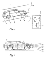
- the vehicle 1 has wheels 4, which protrude downwards over the body 5 of the vehicle 2 and thereby - at least partially - exposed on the sides of the body in recesses thereof, ie from the side are visible.
- a Doppler Lidar- or radar device 6 sends a bundled Lidar- or radar measuring beam 7 obliquely to the direction of travel 3 from the side of the lane 1 just above the road surface, so that the measuring beam 7 hits a passing vehicle 1 approximately in the area of its wheels 4 ,
- the Doppler Lidar- or radar device 6 evaluates, as known in the art, the reception frequency of the reflected from the vehicle 1 and its wheels 4 measuring beam 7, from the Doppler effect frequency shift between emitted and reflected measuring beam 7 in the direction of the measuring beam. 7 lying (projected) component v p of the speed v of the vehicle 1 and the tangential speed v t ( Fig. 2 ) of the wheel 4 at the point of impact of the measuring beam 7 can be determined. Subsequently, the wheels 4 of the vehicle 1 can be detected from this information, as will be explained in more detail later.
- the device 6 is also followed by an evaluation device 8, which carries out the corresponding evaluations of the reception frequency of the measuring beam 7. Lidar / radar device 6 and evaluation device 8 thus together form a device 9 for detecting wheels 4 of a vehicle 1.
- the Doppler lidar / radar device 6 may be of any type known in the art, whether with a continuous, modulated or pulsed measuring beam 7.
- a Doppler frequency shift between the natural frequencies (“carrier frequencies”) may be used.
- a Doppler shift between the pulse rates or modulation frequencies of the emitted and reflected measuring beam 7 can be measured. All such eigen, carrier, pulse or modulation frequencies are understood to mean the term "reception frequency" of the measurement beam 7 as used herein, i.
- reception frequency encompasses any frequency of the measuring beam 7 that can be influenced by a Doppler effect.
- the nature of the measuring beam 7 itself is arbitrary, as long as it is an electromagnetic wave, be it visible light or infrared light as in a lidar device or radio waves (radio waves), especially microwaves, in a radar device.
- the measuring beam 7 is in the explanatory example of FIG Fig. 1 strongly bundled, so that his impact on the body 5 and the wheel 4 has an extremely small diameter.
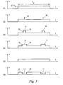
- Fig. 2 shows the scanning curves of a measuring beam 7 bundled in this way, which impinges on the vehicle 1 or its wheels 4 in a substantially punctiform manner, during passage (passage) of the vehicle 1 at the device 9.
- six different sampling curves H1 to H6 are shown by way of example; It is understood that only a single scanning curve H1-H6 occurs at a vehicle passage through a bundled measuring beam 7.
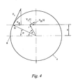
- FIG. 2 shows the reception frequency f of the reflected measuring beam 7 continuously recorded with respect to the scanning progressions H1-H6 by the lidar / radar device 6 over time.
- the Doppler shift ⁇ f of the reception frequency f with respect to the transmission frequency is proportional to the velocity component v p of the respective sampled parts of the vehicle 1 or wheel 4 Fig. 3
- Receiving frequency curves E1 - E6 shown are therefore synonymous with speed gradients.
- the reception frequency curve E2 for each wheel 4 shows a peak 10 of 2vp above the body-rectangular pulse R ,
- the reception frequency profile E5 shows the special case that the measuring beam 7 hits the wheels 4 exactly at the level of their axis, where no tangential speed of the wheel projectable in the direction of the measuring beam 7 is present, so that the wheels 4 are not detectable.
- the reception frequency characteristic E6 scans the wheels 4 at a height between their bottom and their axis and is similar to that of E4, but with the changes 11 - 13 reversed.
- v th (r) The tangential velocity horizontal component v th (r) is thus directly proportional to the considered height h of the scan profile and - while the wheel 4 is scanned - constant over this height h.
- Fig. 5 shows an extension of the method of Fig. 1 to 4 in which, instead of a bundled measuring beam 7, a fanned-out, for example flat or funnel-shaped scattered or expanded measuring beam, referred to below as "measuring beam lobe" 15, is used.
- the measuring beam lobe 15 can be achieved in a lidar device, for example by a superior diverging lens or occurs in radar devices whose bundling is not accurate.
- Fig. 5 shows as an example a Doppler radar device 16, which forms the device 9 together with the evaluation device 8.
- the measuring beam lobe 15 is characterized by the opening angle of the radar antenna used.
- the opening angle (or half-width) of a directional antenna is used to denote the points at which the power has dropped to half (-3 dB) from the maximum.
- ⁇ vertical opening angle (in degrees)
- the opening angle of the radar antenna should allow a good separation of the individual wheels 4 in the measurement signal of the vehicle 1 to be detected.
- the impact area 17 of the measuring beam lobe 15 has substantially the size of a wheel 4 of the vehicle 1 and the wheel 4 does not hit the whole, but slightly above, as in Fig. 7 shown.
- the optimum impact area 17 results from the measuring distance to the vehicle 1, thus the choice of the radar antenna also depends on the geometry of the overall arrangement. Especially Antennas with a gain g of more than 10 dB, depending on the arrangement and frequency of the radar 16, are generally suitable.
- 20 dB antenna gain at a distance of 2 m to the vehicle 1 an area 17 of approximately 56 cm in diameter can be illuminated.
- the reception frequency f splits into a Doppler effect-conditioned mixture 18 of reception frequencies or speeds, wherein the extent of the spread ("frequency spread") in Fig. 6 is denoted by A 1 .
- the occurrence of such frequency spreading 18 can therefore serve as a characteristic for a wheel 4.
- the Doppler effect-related frequency spread 18 in the extent A 1 is parasitically superimposed by a second frequency spreading effect, which is conditioned by the geometry of the measuring beam lobe 15 itself.
- a radar / lidar device 16 observes from its location P 1 different points P 2 ', P 2 "in the impact area 17 of the measurement beam lobe 15 under a different spatial direction 7', 7", respectively, with the horizontal component v th of the tangential velocity v t of the wheel 4 and the speed v of the vehicle body 5 each include a different angle ⁇ 1 , ⁇ 2 in space.
- the Doppler effect-related spreading 18 in the extent A 1 ( Fig. 6 ) is superimposed on the geometry-related spread 18 'to the extent S ( Fig. 8 ) to a "real" receive frequency mixture F over time, as in Fig. 9 shown.
- a frequency spread in the extent A 2 is measured, which is composed of the Doppler-related spreading A 1 and the geometrie employmenten spreading S.
- the geometry-related frequency spread 18 depends essentially only on the installation location and the orientation of the radar / lidar device 16 relative to the roadway 2 or the driving position of the vehicle 1 and can thus eg by reference measurements with vehicles 1 (with hidden wheels or if the Beam 18 only the body 5 hits) to be determined.
- the extent S of the geometrie employmenten frequency spread 18 'can then be used as a reference or default for the actual Raddetektionshabilit that the receiving frequency characteristic of Fig. 9 evaluates and detects a wheel 4 when the recorded curve F of receiving frequencies shows a spread A 2 , which exceeds the predetermined spread S as a reference.
- the Sp Sonella S could alternatively be determined each time on the passage of a vehicle 1 for the current detection process by occurring at the entrance of the vehicle body 5 in the measuring beam lobe 18 in the first milliseconds of a vehicle passage frequency spread 18 'and stored their Sp Dahl S and as Threshold is used for the further Raddetetation.
- the envelope of the Doppler frequency spread 18 corresponds approximately to the circumferential contour of the wheel 4, viewed at angle ⁇ ', ⁇ ", ie, is typically an ellipse, optionally clipped if the area 17 is not the entire wheel 4, see Fig.
- the envelope additionally becomes "blurred” in the extent of the spread S, but still can be analyzed in its approximate form, for example by taking the receive frequency mix F of the reference passage of a reference wheel as a "reference signature" 21 of a rotating one Rades is stored, for example, in a memory 22 of the device 9, to then compare it with the reception frequency characteristic F of a current vehicle passage.
- Fig. 10 shows the real case that at the passage Tp of a vehicle 1 interruptions 23 in the reflected measuring beam lobe 15 and thus in the reception frequency characteristic signal F occur.
- the Doppler radar 16 of the apparatus 9 is constructed using existing radio infrastructure of a road, for example, using WAVE or DSRC radio beacons of a road toll system or WLAN beacons of a roadside Internet infrastructure.
- existing transmission parts of the WLAN, WAVE or DSRC radio beacons can be used as transmission parts of the Doppler radar device 16;
- receiving parts of the five-prong beacons are integrated as receiving parts of the Doppler radar device 16, or the latter at least into the receiving parts of the radio beacons.
- the apparatus and method of the invention may be used in this way, for example as a be implemented on a conventional WLAN, WAVE or DSRC radio beacon running software application.
- the transmission frequency of the radar / lidar device 6 or the measuring beam lobe 15 is constant, i. their time course is a constant course.
- the device 6 emits a measuring beam lobe 15 with a non-constant transmission frequency response, for example, in the case of frequency hopping method in which the frequency is constantly - after a predetermined or known pattern - changes.
- the recorded reception frequency profiles F are recorded relative to the previously known time profile of the transmission frequency of the measuring beam lobe 15, be it constant or alternating, i. referenced or normalized so that the effect of known transmission frequency characteristics can be compensated.
Landscapes
- Engineering & Computer Science (AREA)
- Radar, Positioning & Navigation (AREA)
- Remote Sensing (AREA)
- Physics & Mathematics (AREA)
- General Physics & Mathematics (AREA)
- Computer Networks & Wireless Communication (AREA)
- Chemical & Material Sciences (AREA)
- Analytical Chemistry (AREA)
- Electromagnetism (AREA)
- Radar Systems Or Details Thereof (AREA)
- Traffic Control Systems (AREA)
Description
- Die vorliegende Erfindung betrifft ein Verfahren und eine Vorrichtung zur Detektion von Rädern eines Fahrzeugs, das auf einer Fahrbahn in einer Fahrtrichtung fährt und dessen Räder zumindest teilweise seitlich freiliegen.
- Das Detektieren von Fahrzeugrädern ist bei zahlreichen Anwendungen von Interesse. So kann aus dem Erkennen von Rädern mit Sicherheit das Befahren einer bestimmten Verkehrsfläche erkannt werden, beispielsweise zur Grenzüberwachung oder zur Auslösung bestimmter Aktionen, wie das Auslösen eines Alarms, Einschalten einer Beleuchtung, Öffnen eines Schrankens, Aufnehmen eines Fotos zu Überwachungszwecken usw. Auch moderne Verkehrsgebührensysteme stellen häufig zur Gebührenbemessung auf die Achsanzahl von Fahrzeugen ab, sodass das Detektieren von Rädern (Radachsen) auch eine wichtige Grundlage für Straßenmaut- oder Parkgebührensysteme sein kann.
- Aus der
DE 10 2008 037 233 A1 ist es bekannt, Räder eines sich bewegenden Fahrzeugs aufgrund ihrer gegenüber dem restlichen Fahrzeug unterschiedlichen horizontalen Komponente der Tangentialgeschwindigkeit, die eine entsprechende Doppler-Frequenzverschiebung eines Radar-Messstrahls bewirkt, zu detektieren. Dazu wird ein Radar-Geschwindigkeitsmesser verwendet, welcher mit einer Radar-Strahlungskeule den unteren Bereich passierender Fahrzeuge bestrahlt und aus dem zurückgehaltenen Empfangsfrequenzgemisch ein einziges Geschwindigkeitsmesssignal mittelt, das an den Orten der Räder Signalmaxima zeigt. Eine automatische Detektion solcher Maxima in einem Signalverlauf erfordert eine signalanalytische Extremwertsuche und ist dementsprechend aufwändig. Darüber hinaus können z.B. Lücken zwischen einem Zugfahrzeug und seinem Anhänger Signalminima und damit zwischenliegende "falsche" Maxima vortäuschen, welche zu einer fehlerhaften Raddetektion führen. - Die Erfindung setzt sich zum Ziel, Verfahren und Vorrichtungen zur Raddetektion zu schaffen, welche eine sicherere Detektion ermöglichen als die bekannten Lösungen.
- Dieses Ziel wird in einem ersten Aspekt der Erfindung mit einem Verfahren erreicht, das sich auszeichnet durch die Schritte
- Aussenden einer elektromagnetischen Messstrahlkeule mit einem bekannten zeitlichen Verlauf ihrer Frequenz von der Seite der Fahrbahn her auf einen Bereich über der Fahrbahn und schräg zur Fahrtrichtung,
- Empfangen der von einem passierenden Fahrzeug reflektierten Messstrahlkeule und Aufzeichnen aller ihrer Frequenzen im zeitlichen Verlauf relativ zum bekannten Verlauf als Empfangsfrequenzgemischverlauf, und
- Detektieren einer während der Fahrzeugpassage auftretenden Frequenzaufspreizung im aufgezeichneten Verlauf des Empfangsfrequenzgemischs, welche einen vorgegebenen Schwellwert übersteigt, als Rad.
- Die Erfindung beruht auf dem neuartigen Ansatz, Räder eines sich bewegenden Fahrzeugs aufgrund ihrer gegenüber dem restlichen Fahrzeug unterschiedlichen horizontalen Komponente der Tangentialgeschwindigkeit, die eine entsprechende Doppler-Frequenzverschiebung eines Lidar- oder Radar-Messstrahls bewirkt, zu detektieren. Bei Verwendung eines über einen größeren Strahlquerschnitt ausgedehnten Messstrahls ("Messstrahlkeule"), welcher z.B. kegelförmig über einen Raumwinkel aufgefächert bzw. verteilt ist, trifft dieser zumindest einen Teil eines passierenden Rades über einen ausgedehnten Auftreffbereich, z.B. eine Ellipse mit einer Höhe bzw. Breite im Bereich von 10 cm - 50 cm. Auf jeder verschiedenen Höhe eines sich drehenden Rades hat dieses eine - über seine Breite konstante - verschiedene horizontale Komponente seiner Tangentialgeschwindigkeit und erzeugt damit eine unterschiedliche Dopplerfrequenzverschiebung, welche zu einer "Aufsplitterung" bzw. "Aufspreizung" der Sendefrequenz der Messstrahlkeule auf eine Vielzahl vom drehenden Rad zurückgeworfener Empfangsfrequenzen führt. Ein sich drehendes Rad erzeugt damit, wenn es von einer Messstrahlkeule über einen ausgedehnten Höhenbereich getroffen wird, über seine Höhe eine Frequenzaufspreizung im Empfangsspektrum, was zur Detektion des Rades ausgenützt werden kann.
- Der vorgenannte Effekt ist von einem zweiten parasitären Frequenzaufspreizungseffekt überlagert, welcher auf die unterschiedlichen Projektionswinkel der horizontalen Komponente der Tangentialgeschwindigkeit auf die Richtung zum Empfänger zurückzuführen ist: diese Projektionsrichtung variiert je nach betrachtetem Reflexionsort im Auftreffbereich. Dieser zweite Aufspreizungseffekt ist davon unabhängig, ob gerade die Fahrzeugkarosserie oder das sich drehende Rad den Empfänger passiert, und ist einzig durch die geometrischen Randbedingungen der Messanordnung bestimmt. Das Maß an Aufspreizung, welches zur Detektion eines Rades von der erstgenannten dopplereffektbedingten Frequenzaufsplitterung überschritten werden muss, wird daher so festgelegt, dass die durch die zweitgenannte geometriebedingte Frequenzaufsplitterung hervorgerufene Aufspreizung darunterliegt. Im Ergebnis wird ein Raddetektionsverfahren mit hoher Detektionssicherheit erzielt, u.zw. aufgrund der von einem Rad hervorgerufenen "Doppler-Signatur".
- Bevorzugt wird somit der vorgegebene Schwellwert zuvor aus jener Frequenzaufspreizung ermittelt, die bei der Passage eines radlosen Teils eines Fahrzeugs auftritt. Dadurch kann das Verfahren vor Ort durch Referenzmessungen kalibriert werden.
- In einem zweiten Aspekt schafft die Erfindung eine Vorrichtung zur Detektion von Rädern eines Fahrzeugs, das auf einer Fahrbahn in einer Fahrtrichtung fährt und dessen Räder zumindest teilweise seitlich freiliegen, gekennzeichnet durch
zumindest ein Doppler-Lidar- oder -Radargerät, das eine elektromagnetische Messstrahlkeule mit einem bekannten zeitlichen Verlauf ihrer Frequenz auf ein Ziel aussendet und alle Frequenzen der vom Ziel reflektierten Messstrahlkeule im zeitlichen Verlauf relativ zum bekannten Verlauf als Empfangsfrequenzgemischverlauf aufzeichnet,
wobei die Messstrahlkeule von der Seite der Fahrbahn her auf einen Bereich über der Fahrbahn und schräg zur Fahrtrichtung orientiert ist, und
eine nachgeordnete Auswerteeinrichtung, welche eine während der Fahrzeugpassage auftretende Frequenzaufspreizung im aufgezeichneten Verlauf des Empfangsfrequenzgemischs, die einen vorgegebenen Schwellwert übersteigt, als Rad detektiert. - Hinsichtlich der Vorteile der erfindungsgemäßen Vorrichtung wird auf die obigen Ausführungen zum erfindungsgemäßen Verfahren verwiesen.
- Die Erfindung eignet sich - wenn sie mit einem Doppler-Radargerät arbeitet - besonders zum Zusammenbau mit den Funkbaken einer bereits vorhandenen Funk-Straßeninfrastruktur, wie WLAN (wireless local area network), WAVE (wireless access in a vehicle environment) oder DSRC (deticated short range communication). Eine besonders vorteilhafte Ausführungsform der Erfindung zeichnet sich demgemäß dadurch aus, dass das Doppler-Radargerät durch eine straßenseitige WLAN-, WAVE- oder DSRC-Funkbake gebildet ist.
- Weitere Merkmale und Vorteile des Verfahrens und der Vorrichtung der Erfindung ergeben sich aus der nachfolgenden Beschreibung eines bevorzugten Ausführungsbeispiels unter Bezugnahme auf die begleitenden Zeichnungen, in denen zeigt:
-
Fig. 1 eine erste Ausführungsform einer Vorrichtung zur Raddetektion zur Erläuterung der Grundlagen der Erfindung in einer schematischen Perspektivansicht; -
Fig. 2 mehrere beispielhafte Abtastverläufe des Messstrahls der Vorrichtung vonFig. 1 an einem passierenden Fahrzeug; -
Fig. 3 Zeitdiagramme der ermittelten Empfangsfrequenz- bzw. Geschwindigkeitsverläufe zu den Abtastverläufen vonFig. 2 ; -
Fig. 4 die Geschwindigkeitsverhältnisse an einem sich drehenden Rad im Detail; -
Fig. 5 eine Ausführungsform der Vorrichtung der Erfindung in einer schematischen Perspektivansicht; -
Fig. 6 die Superposition von mehreren Empfangsfrequenz- bzw. Geschwindigkeitsverläufen vonFig. 3 zur Veranschaulichung der dopplerbedingten Frequenzaufspreizung bei der Passage eines Rades; -
Fig. 7 die geometrischen Verhältnisse in der Messstrahlkeule der Vorrichtung vonFig. 5 zur Veranschaulichung der geometriebedingten Frequenzaufspreizung bei der Passage eines Fahrzeugs; -
Fig. 8 den Effekt der geometriebedingten Frequenzaufspreizung bei der Passage im zeitlichen Verlauf; -
Fig. 9 die kombinierte Auswirkung der geometriebedingten Frequenzaufspreizung vonFig. 8 und der dopplerbedingten Frequenzaufspreizung vonFig. 6 bei der Passage eines Fahrzeugs im zeitlichen Verlauf; und -
Fig. 10 eine Variante vonFig. 9 . - In
Fig. 1 bewegt sich ein Fahrzeug 1 auf einer Fahrbahn 2 in einer Fahrtrichtung 3. Das Fahrzeug 1 besitzt Räder 4, welche nach unten über die Karosserie 5 des Fahrzeugs 2 vorragen und dabei - zumindest teilweise - an den Seiten der Karosserie in Ausnehmungen derselben freiliegen, d.h. von der Seite her sichtbar sind. - Ein Doppler-Lidar- oder Radargerät 6 sendet einen gebündelten Lidar- oder Radar-Messstrahl 7 schräg zur Fahrtrichtung 3 von der Seite der Fahrbahn 1 her knapp über die Fahrbahnoberfläche aus, sodass der Messstrahl 7 ein passierendes Fahrzeug 1 etwa im Bereich seiner Räder 4 trifft.
- Das Doppler-Lidar- bzw. Radargerät 6 wertet, wie in der Technik bekannt, die Empfangsfrequenz des vom Fahrzeug 1 bzw. seinen Rädern 4 reflektierten Messstrahls 7 aus, wobei aus der dopplereffektbedingten Frequenzverschiebung zwischen ausgesandtem und reflektiertem Messstrahl 7 die in Richtung des Messstrahls 7 liegende (projizierte) Komponente vp der Geschwindigkeit v des Fahrzeugs 1 bzw. der Tangentialgeschwindigkeit vt (
Fig. 2 ) des Rades 4 am Auftreffpunkt des Messstrahls 7 ermittelt werden kann. In weiterer Folge können aus dieser Information die Räder 4 des Fahrzeugs 1 detektiert werden, wie später noch ausführlicher erläutert wird. Zu diesem Zweck ist dem Gerät 6 auch eine Auswerteeinrichtung 8 nachgeschaltet, welche die entsprechenden Auswertungen der Empfangsfrequenz des Messstrahls 7 vornimmt. Lidar/Radar-Gerät 6 und Auswerteeinrichtung 8 bilden somit zusammen eine Vorrichtung 9 zur Detektion von Rädern 4 eines Fahrzeugs 1. - Das Doppler-Lidar/Radar-Gerät 6 kann an sich von jeder in der Technik bekannten Art sein, sei es mit einem kontinuierlichen, modulierten oder einem gepulsten Messstrahl 7. Bei einem kontinuierlichen Messstrahl 7 kann eine Dopplerfrequenzverschiebung zwischen den Eigenfrequenzen ("Trägerfrequenzen") des ausgesandten und des reflektierten Messstrahl 7 z.B. durch Interferenzmessung ermittelt werden. Bei einem gepulsten oder modulierten Messstrahl kann eine Dopplerverschiebung zwischen den Impulsraten bzw. Modulationsfrequenzen des ausgesandten und des reflektierten Messstrahls 7 gemessen werden. Alle solche Eigen-, Träger-, Impuls- oder Modulationsfrequenzen werden unter dem hier verwendeten Begriff der "Empfangsfrequenz" des Messstrahls 7 verstanden, d.h. der Begriff Empfangsfrequenz umfasst jedwede durch einen Dopplereffekt beeinflussbare Frequenz des Messstrahls 7.
- Grundsätzlich ist auch die Natur des Messstrahls 7 selbst beliebig, solange es sich um eine elektromagnetische Welle handelt, sei es sichtbares Licht oder Infrarotlicht wie bei einem Lidargerät oder Radiowellen (Funkwellen), insbesondere Mikrowellen, bei einem Radargerät.
- Der Messstrahl 7 ist in dem Erläuterungsbeispiel von
Fig. 1 stark gebündelt, sodass sein Auftreffpunkt auf der Karosserie 5 bzw. dem Rad 4 einen äußerst geringen Durchmesser hat. -
Fig. 2 zeigt die Abtastverläufe eines derart gebündelten Messstrahls 7, der im wesentlichen punktförmig auf das Fahrzeug 1 bzw. dessen Räder 4 auftrifft, während der Vorbeifahrt (Passage) des Fahrzeugs 1 an der Vorrichtung 9. Zu Erläuterungszwecken sind beispielhaft sechs unterschiedliche Abtastverläufe H1 bis H6 gezeigt; es versteht sich, dass durch einen gebündelten Messstrahl 7 bei einer Fahrzeugpassage jeweils nur ein einziger Abtastverlauf H1 - H6 auftritt. -
Fig. 3 zeigt die zu den Abtastverläufen H1 - H6 vom Lidar/Radar-Gerät 6 fortlaufend erfasste Empfangsfrequenz f des reflektierten Messstrahls 7 über der Zeit. Die Dopplerverschiebung Δf der Empfangsfrequenz f gegenüber der Sendefrequenz ist proportional zur Geschwindigkeitskomponente vp der jeweils abgetasteten Teile des Fahrzeugs 1 bzw. Rades 4. Die inFig. 3 dargestellten Empfangsfrequenzverläufe E1 - E6 sind daher gleichbedeutend mit Geschwindigkeitsverläufen. - Aus dem Empfangsfrequenzverlauf E1 von
Fig. 3 ist ersichtlich, dass beim Abtastverlauf H1, welcher die Karosserie 5 des Fahrzeugs 1 außerhalb der Räder 4 trifft, während Dauer Tp der Karossieriepassage eine weitgehend konstante Empfangsfrequenzverschiebung Δf des Messstrahls 7 und damit Geschwindigkeitskomponente vp gemessen wird, welche sich als Rechteckimpuls R im Empfangsfrequenzverlauf äußert. - Für den Abtastverlauf H2, welcher die Räder 4 an ihrer obersten Stelle berührt, wo ihre Tangentialgeschwindigkeit vt sich zur Fahrzeuggeschwindigkeit v addiert, zeigt der Empfangsfrequenzverlauf E2 für jedes Rad 4 eine Spitze ("peak") 10 von 2vp über dem Karosserie-Rechteckimpulses R.
- Wenn der Messstrahl 7 die Räder 4 auf einer Höhe zwischen der Radachse und der Radoberseite schneidet, wie bei den Abtastverläufen an H3 und H4, wird bei der Passage eines Rades 4 entsprechend der Projektion vp seiner Tangentialgeschwindigkeit vt auf die Messstrahlrichtung eine sich gegenüber dem Karosserie-Impuls R nochmals sprunghaft verändernde Dopplerverschiebung und damit Empfangsfrequenz bzw. Geschwindigkeit gemessen, wie durch die Rechteck-Impulse 11 der Verläufe E3 und E4 veranschaulicht. Jeder Impuls 11 umfasst jeweils eine ansteigende Flanke 12 und eine darauffolgende abfallende Flanke 13, d.h. zwei aufeinanderfolgende abwechselnde Frequenz-"Sprünge".
- Der Empfangsfrequenzverlauf E5 zeigt den Sonderfall, dass der Messstrahl 7 die Räder 4 genau auf Höhe ihrer Achse trifft, wo keine in Richtung des Messstrahls 7 projizierbare Tangentialgeschwindigkeit des Rades vorhanden ist, sodass die Räder 4 nicht detektierbar sind.
- Der Empfangsfrequenzverlauf E6 tastet die Räder 4 auf einer Höhe zwischen ihrer Unterseite und ihrer Achse ab und ähnelt jenem von E4, nur mit umgekehrten Änderungen 11 - 13.
-
Fig. 4 zeigt analytisch das Ausmaß des Versatzes 11 bei der Passage eines Rades 4 in Abhängigkeit der Höhe h des jeweiligen Abtastverlaufes H1 bis H6 gegenüber der Radachse A, beispielsweise am Abtastverlauf H4. Sei R der Radius des Rades 4 und r ein beliebiger Radius innerhalb des Rades 4, dann ist die Tangentialgeschwindigkeit vt (r) auf einem Radius r proportional diesem Radius r, u.zw. gemäß
- Die in Fahrtrichtung 3 liegende Horizontalkomponente vth(r) der Tangentialgeschwindigkeit vt (r) unter einem Winkel α ist eine Sinus-Projektion entsprechend

- Mit

ergibt sich die Tangentialgeschwindigkeits-Horizontalkomponente vth(r) damit zu
- Die Tangentialgeschwindigkeits-Horizontalkomponente vth(r) ist somit direkt proportional der jeweils betrachteten Höhe h des Abtastverlaufs und - während das Rad 4 abgetastet wird - über diese Höhe h konstant.
-
Fig. 5 zeigt eine Erweiterung des Verfahrens derFig. 1 bis 4 , bei welchem anstelle eines gebündelten Messstrahls 7 ein aufgefächerter, z.B. flächig oder trichterförmig gestreuter bzw. aufgeweiteter Messstrahl, im Folgenden kurz "Messstrahlkeule" 15 genannte, verwendet wird. Die Messstrahlkeule 15 kann bei einem Lidargerät z.B. durch eine vorgesetzte Zerstreuungslinse erreicht werden oder tritt bei Radargeräten auf, deren Bündelung nicht exakt ist.Fig. 5 zeigt als Beispiel ein Doppler-Radargerät 16, welches zusammen mit der Auswerteeinrichtung 8 die Vorrichtung 9 bildet. - Im Falle von Radar wird die Messstrahlkeule 15 durch den Öffnungswinkel der verwendeten Radarantenne charakterisiert. Unter dem Öffnungswinkel (oder auch Halbwertsbreite) einer Richtantenne bezeichnet man jeweils die Punkte, wo die Leistung gegenüber dem Maximum auf die Hälfte (-3 dB) abgefallen ist. Wie dem Fachmann geläufig, kann für Richtantennen aus der Kenntnis der jeweiligen Öffnungswinkel der Gewinn der Antenne in ihrer Hauptstrahlrichtung mit folgender Formel geschätzt werden:

wobei
g = Gewinn [dBi]
Δϕ = Horizontaler Öffnungswinkel (in Grad)
Δϑ = Vertikaler Öffnungswinkel (in Grad) - Der Öffnungswinkel der Radarantenne sollte eine gute Separierung der einzelnen Räder 4 im Messsignal des zu detektierenden Fahrzeugs 1 erlauben. Somit ist es besonders günstig, wenn der Auftreffbereich 17 der Messstrahlkeule 15 im wesentlichen die Größe eines Rades 4 des Fahrzeugs 1 hat und das Rad 4 nicht zur Gänze, sondern etwas oberhalb trifft, wie in
Fig. 7 gezeigt. Der optimale Auftreffbereich 17 ergibt sich aus dem Messabstand zum Fahrzeug 1, somit hängt auch die Wahl der Radarantenne von der Geometrie der Gesamtanordnung ab. Besonders geeignet sind allgemein Antennen mit einem Gewinn g von über 10 dB, abhängig von der Anordnung und Frequenz des Radargeräts 16. - Richtantennen weisen üblicherweise einen Antennengewinn g von über 20 dB (entspricht einem Öffnungswinkel Δϕ = Δϑ = ca. 16°). Somit lässt sich bei 20 dB Antennengewinn in 2 m Abstand zum Fahrzeug 1 ein Bereich 17 von ca. 56 cm Durchmesser beleuchten. Für weiter entfernte Fahrzeuge 1 kann ein Antennengewinn g von 30 dB notwendig sein, um einen Öffnungswinkel Δϕ = Δϑ = ca. 5° zu erreichen, der in 10 m Abstand einen Bereich 17 von ca. 90 cm Ausleuchtung bedeutet.
- Bei Verwendung einer solchen Messstrahlkeule 15, welche einen größeren Bereich 17 des Fahrzeugs 1 bzw. der Räder 4 trifft, superponieren sich die von verschiedenen im Bereich 17 liegenden Auftreffpunkten - vgl. die beispielhaften Abtastverläufe H1 bis H6 in
Fig. 2 - jeweils herrührenden Empfangsfrequenzen - vgl. E1 bis E6 - zu einem Gemisch 18 verschiedener Empfangsfrequenzen bzw. Geschwindigkeiten, sieheFig. 6 . Mit anderen Worten splittet bzw. spreizt sich während der Passage Tp eines Fahrzeugs 1 bei Auftreten eines Rades 4 die Empfangsfrequenz f in ein dopplereffektbedingtes Gemisch 18 von Empfangsfrequenzen bzw. Geschwindigkeiten auf, wobei das Ausmaß der Aufspreizung ("frequency spread") inFig. 6 mit A1 bezeichnet ist. Das Auftreten einer solchen Frequenzaufspreizung 18 kann daher als Kennzeichen für ein Rad 4 dienen. - Die dopplereffektbedingte Frequenzaufspreizung 18 im Ausmaß A1 ist parasitär von einem zweiten Frequenzaufspreizungseffekt überlagert, der durch die Geometrie der Messstrahlkeule 15 selbst bedingt ist. Wie aus
Fig. 7 ersichtlich, beobachtet ein Radar/Lidar-Gerät 16 von seinem Ort P1 aus verschiedene Punkte P2', P2" im Auftreffbereich 17 der Messstrahlkeule 15 unter jeweils einer anderen Raumrichtung 7', 7", die mit der Horizontalkomponente vth der Tangentialgeschwindigkeit vt des Rades 4 bzw. der Geschwindigkeit v der Fahrzeugkarosserie 5 jeweils einen anderen Winkel β1, β2 im Raum einschließt. Die Projektion der Geschwindigkeit v bzw. Vth auf die jeweilige Messstrahlrichtung 7', 7" usw. in der Messstrahlkeule 15 führt dadurch - über den Bereich 17 - zu einer geometriebedingten Aufsplitterung bzw. Aufspreizung ("frequency spread") 18' der Empfangsfrequenzen, wie sie inFig. 8 z.B. für die Geschwindigkeit v der Fahrzeugkarosserie 5 auf der Höhe H1 als - geometriebedingt aufgespreizter - Empfangsfrequenzverlauf E1' dargestellt ist und das Ausmaß S einnimmt. - Die dopplereffektbedingte Aufspreizung 18 im Ausmaß A1 (
Fig. 6 ) überlagert sich mit der geometriebedingten Aufspreizung 18' im Ausmaß S (Fig. 8 ) zu einem "realen" Empfangsfrequenzgemisch F im zeitlichen Verlauf, wie inFig. 9 dargestellt. An den Orten der Räder 4 wird eine Frequenzaufspreizung im Ausmaß A2 gemessen, welche sich aus der dopplerbedingten Aufspreizung A1 und der geometriebedingten Aufspreizung S zusammensetzt. - Die geometriebedingte Frequenzaufspreizung 18' hängt im Wesentlichen nur von dem Einbauort und der Orientierung des Radar/Lidar-Geräts 16 gegenüber der Fahrbahn 2 bzw. der Fahrlage des Fahrzeugs 1 ab und kann somit z.B. durch Referenzmessungen mit Fahrzeugen 1 (mit verdeckten Rädern oder wenn die Messstrahlkeule 18 nur die Karosserie 5 trifft) eruiert werden. Das Ausmaß S der geometriebedingten Frequenzaufspreizung 18' kann dann als Referenz bzw. Vorgabe für das eigentliche Raddetektionsverfahren herangezogen werden, das den Empfangsfrequenzverlauf von
Fig. 9 auswertet und ein Rad 4 detektiert, wenn der aufgezeichnete Verlauf F von Empfangsfrequenzen eine Aufspreizung A2 zeigt, welche das als Referenz vorgegebene Spreizmaß S übersteigt. - Das Spreizmaß S könnte alternativ jeweils aufs Neue bei der Passage eines Fahrzeugs 1 für den aktuellen Detektionsvorgang ermittelt werden, indem die beim Eintritt der Fahrzeugkarosserie 5 in die Messstrahlkeule 18 in den ersten Millisekunden einer Fahrzeugpassage auftretende Frequenzaufspreizung 18' ausgewertet und ihr Spreizmaß S gespeichert und als Schwellwert für die weitere Raddetektion herangezogen wird.
- Wie anhand von
Fig. 4 und Gl. (4) ersichtlich, entspricht die Einhüllende der dopplerbedingten Frequenzaufspreizung 18 etwa der Umfangskontur das Rades 4, unter dem Winkel β', β" betrachtet, d.h. ist in der Regel eine Ellipse, die gegebenenfalls abgeschnitten ist, wenn der Bereich 17 nicht das gesamte Rad 4 abdeckt, sieheFig. 6 . Unter zusätzlicher Berücksichtigung der geometriebedingten Frequenzaufspreizung 18' wird die Einhüllende zusätzlich im Ausmaß der Spreizung S "unscharf", doch kann sie trotzdem noch in ihrer ungefähren Form analysiert werden, beispielsweise indem das Empfangsfrequenzgemisch F der Referenzpassage eines Referenzrads als "Referenzsignatur" 21 eines sich drehenden Rades gespeichert wird, z.B. in einem Speicher 22 der Vorrichtung 9, um es anschließend mit dem Empfangsfrequenzverlauf F einer aktuellen Fahrzeugpassage zu vergleichen. -
Fig. 10 zeigt den realen Fall, dass bei der Passage Tp eines Fahrzeugs 1 Unterbrechungen 23 in der reflektierten Messstrahlkeule 15 und damit im Empfangsfrequenzverlaufsignal F auftreten. Beim Vergleich der Referenzsignaturen 21 mit einem solchen realen Empfangsfrequenzverlauf F können daher geeignete Kontur-, Flächen- und/oder Formenvergleiche ("best-fit match") vorgenommen werden, um auch in solchen Fällen hohe Erkennungssicherheit zu erreichen. - In einer vorteilhaften praktischen Realisierung der Ausführungsform von
Fig. 5 wird das Doppler-Radargerät 16 der Vorrichtung 9 unter Verwendung bestehender Funk-Infrastruktur einer Straße aufgebaut, z.B. unter Verwendung von WAVE- oder DSRC-Funkbaken eines Straßenmautsystems oder WLAN-Funkbaken einer straßenseitigen Internet-Infrastruktur. Dadurch können bereits vorhandene Sendeteile der WLAN-, WAVE- oder DSRC-Funkbaken als Sendeteile des Doppler-Radargeräts 16 verwendet werden; ebenso Empfangsteile der Fünkbaken als Empfangsteile des Doppler-Radargeräts 16, oder letztere zumindest in die Empfangsteile der Funkbaken integriert werden. Die Vorrichtung und das Verfahren der Erfindung können auf diese Weise z.B. als eine auf einer herkömmlichen WLAN-, WAVE- oder DSRC-Funkbake laufende Softwareapplikation implementiert werden. - Bislang wurde davon ausgegangen, dass die Sendefreuqenz des Radar/Lidar-Geräts 6 bzw. der Messstrahlkeule 15 konstant ist, d.h. ihr zeitlicher Verlauf ein konstanter Verlauf ist. Es ist jedoch auch möglich, dass das Gerät 6 eine Messstrahlkeule 15 mit einem zeitlich nicht-konstanten Sendefrequenzverlauf aussendet, beispielsweise im Falle von Frequency-Hopping-Verfahren, bei denen die Frequenz ständig - nach einem vorgegebenen bzw. bekannten Muster - wechselt. Die aufgezeichneten Empfangsfrequenzverläufe F werden relativ zu dem vorbekannten zeitlichen Verlauf der Sendefrequenz der Messstrahlkeule 15 - sei er konstant oder wechselnd - aufgezeichnet, d.h. auf diesen referenziert bzw. normiert, so dass der Effekt von bekannten Sendefrequenzverläufen kompensiert werden kann.
- Die Erfindung ist demgemäß nicht auf die dargestellten Ausführungsformen beschränkt, sondern umfasst alle Varianten und Modifikationen, die in den Rahmen der angeschlossenen Ansprüche fallen.
Claims (4)
- Verfahren zur Detektion von Rädern (4) eines Fahrzeugs (1), das auf einer Fahrbahn (2) in einer Fahrtrichtung (3) fährt und dessen Räder (4) zumindest teilweise seitlich freiliegen, mit dem Schritt:Aussenden einer elektromagnetischen Messstrahlkeule (15) mit einem bekannten zeitlichen Verlauf ihrer Frequenz von der Seite der Fahrbahn (2) her auf einen Bereich über der Fahrbahn (2) und schräg zur Fahrtrichtung (3),gekennzeichnet durch die Schritte:Empfangen der von einem passierenden Fahrzeug (1) reflektierten Messstrahlkeule (15) und Aufzeichnen aller ihrer Frequenzen im zeitlichen Verlauf relativ zum bekannten Verlauf als Empfangsfrequenzgemischverlauf, undDetektieren einer während der Fahrzeugpassage (Tp) auftretenden Frequenzaufspreizung (A2) im aufgezeichneten Verlauf des Empfangsfrequenzgemischs (F), welche einen vorgegebenen Schwellwert (S) übersteigt, als Rad.
- Verfahren nach Anspruch 1, dadurch gekennzeichnet, dass in einem vorhergehenden Schritt der vorgegebene Schwellwert (S) aus der Frequenzaufspreizung (18') ermittelt wird, die bei der Passage eines radlosen Teils eines Fahrzeugs (1) auftritt.
- Vorrichtung zur Detektion von Rädern (4) eines Fahrzeugs (1), das auf einer Fahrbahn (2) in einer Fahrtrichtung (3) fährt und dessen Räder (4) zumindest teilweise seitlich freiliegen, gekennzeichnet durch
zumindest ein Doppler-Lidar- oder -Radargerät (6), das eine elektromagnetische Messstrahlkeule (15) mit einem bekannten zeitlichen Verlauf ihrer Frequenz auf ein Ziel aussendet und alle Frequenzen der vom Ziel reflektierten Messstrahlkeule (15) im zeitlichen Verlauf relativ zum bekannten Verlauf als Empfangsfrequenzgemischverlauf aufzeichnet,
wobei die Messstrahlkeule (15) von der Seite der Fahrbahn (2) her auf einen Bereich über der Fahrbahn (2) und schräg zur Fahrtrichtung (3) orientiert ist, und
eine nachgeordnete Auswerteeinrichtung (8), welche eine während der Fahrzeugpassage (Tp) auftretende Frequenzaufspreizung (A2) im aufgezeichneten Verlauf des Empfangsfrequenzgemischs (F), die einen vorgegebenen Schwellwert (S) übersteigt, als Rad (4) detektiert. - Vorrichtung nach Anspruch 3 mit einem Doppler-Radargerät (6), dadurch gekennzeichnet, dass dieses durch eine stra-ßenseitige WLAN-, WAVE- oder DSRC-Funkbake gebildet ist.
Priority Applications (29)
| Application Number | Priority Date | Filing Date | Title |
|---|---|---|---|
| ES11450080.4T ES2444630T3 (es) | 2011-06-21 | 2011-06-21 | Procedimiento y dispositivo para detectar ruedas |
| PL11450080T PL2538239T3 (pl) | 2011-06-21 | 2011-06-21 | Sposób i urządzenie do wykrywania kół pojazdu |
| PT114500804T PT2538239E (pt) | 2011-06-21 | 2011-06-21 | Método e dispositivo para deteção de rodas |
| SI201130105T SI2538239T1 (sl) | 2011-06-21 | 2011-06-21 | Postopek in naprava za zaznavanje koles |
| EP11450080.4A EP2538239B1 (de) | 2011-06-21 | 2011-06-21 | Verfahren und Vorrichtung zur Detektion von Rädern |
| DK11450080.4T DK2538239T3 (en) | 2011-06-21 | 2011-06-21 | Devices and method for detection of wheels |
| CA2775982A CA2775982A1 (en) | 2011-06-21 | 2012-04-25 | Method and apparatus for detecting wheels |
| AU2012203252A AU2012203252B2 (en) | 2011-06-21 | 2012-05-31 | Method and apparatus for detecting wheels |
| US13/489,322 US8884812B2 (en) | 2011-06-21 | 2012-06-05 | Method and apparatus for detecting vehicle wheels |
| CN2012101925640A CN102841340A (zh) | 2011-06-21 | 2012-06-12 | 用于检测车轮的方法和设备 |
| ZA2012/04491A ZA201204491B (en) | 2011-06-21 | 2012-06-18 | Method and apparatus for detecting wheels |
| SI201230286T SI2724175T1 (sl) | 2011-06-21 | 2012-06-19 | Postopek in naprava za zaznavanje vrtečega se kolesa |
| US14/127,875 US9507014B2 (en) | 2011-06-21 | 2012-06-19 | Method and device for detecting a rotating wheel |
| ES12729537.6T ES2544736T3 (es) | 2011-06-21 | 2012-06-19 | Procedimiento y dispositivo para detectar una rueda en rotación |
| PT127295376T PT2724175E (pt) | 2011-06-21 | 2012-06-19 | Método e dispositivo para a deteção de uma roda em rotação |
| RU2013156821/07A RU2577516C2 (ru) | 2011-06-21 | 2012-06-19 | Способ и устройство для обнаружения вращающегося колеса |
| DK12729537.6T DK2724175T3 (en) | 2011-06-21 | 2012-06-19 | Method and device for detection of a rotating wheels |
| CN201280030339.5A CN103620439A (zh) | 2011-06-21 | 2012-06-19 | 用于对转动的车轮进行检测的方法和设备 |
| PCT/EP2012/061645 WO2012175470A1 (de) | 2011-06-21 | 2012-06-19 | Verfahren und vorrichtung zur detektion eines sich drehenden rades |
| CA2835530A CA2835530A1 (en) | 2011-06-21 | 2012-06-19 | Method and device for detecting a rotating wheel |
| NZ617610A NZ617610B2 (en) | 2011-06-21 | 2012-06-19 | Method and device for detecting a rotating wheel |
| HUE12729537A HUE025253T2 (en) | 2011-06-21 | 2012-06-19 | Procedure and apparatus for detecting rotating wheel |
| AU2012274174A AU2012274174B2 (en) | 2011-06-21 | 2012-06-19 | Method and device for detecting a rotating wheel |
| EP12729537.6A EP2724175B1 (de) | 2011-06-21 | 2012-06-19 | Verfahren und vorrichtung zur detektion eines sich drehenden rades |
| PL12729537T PL2724175T3 (pl) | 2011-06-21 | 2012-06-19 | Sposób i urządzenie do wykrywania obracającego się koła |
| RU2012125815/07A RU2580947C2 (ru) | 2011-06-21 | 2012-06-20 | Способ и устройство детектирования колес |
| CL2012001703A CL2012001703A1 (es) | 2011-06-21 | 2012-06-21 | Metodo y aparato para detectar las ruedas de un vehiculo que esta circulando en una carretera en una direccion de desplazamiento, las ruedas de los vehiculos estan al menos parcialmente expuestos lateralmente, emitiendo un haz de medición lobular electromagnetica que tiene una frecuencia de progresion temporal conocida desde el lado de la calzada en una zona superior de la calzada y con una inclinacion con respecto a la direccion de viaje |
| CL2013003644A CL2013003644A1 (es) | 2011-06-21 | 2013-12-19 | Metodo para detectar una rueda girando de un vehiculo que esta viajando en un camino en una direccion de desplazamiento que comprende los pasos de emitir un haz de medicion electromagnetico que tiene una progresion temporal conocida de su frecuencia, recibir un haz medicion reflejado y registrar la progresion temporal de sus frecuencias relativas; y aparato. |
| ZA2013/09739A ZA201309739B (en) | 2011-06-21 | 2013-12-23 | Method and device for detecting a rotating wheel |
Applications Claiming Priority (1)
| Application Number | Priority Date | Filing Date | Title |
|---|---|---|---|
| EP11450080.4A EP2538239B1 (de) | 2011-06-21 | 2011-06-21 | Verfahren und Vorrichtung zur Detektion von Rädern |
Publications (2)
| Publication Number | Publication Date |
|---|---|
| EP2538239A1 EP2538239A1 (de) | 2012-12-26 |
| EP2538239B1 true EP2538239B1 (de) | 2013-11-13 |
Family
ID=44720372
Family Applications (1)
| Application Number | Title | Priority Date | Filing Date |
|---|---|---|---|
| EP11450080.4A Not-in-force EP2538239B1 (de) | 2011-06-21 | 2011-06-21 | Verfahren und Vorrichtung zur Detektion von Rädern |
Country Status (13)
| Country | Link |
|---|---|
| US (1) | US8884812B2 (de) |
| EP (1) | EP2538239B1 (de) |
| CN (1) | CN102841340A (de) |
| AU (1) | AU2012203252B2 (de) |
| CA (1) | CA2775982A1 (de) |
| CL (1) | CL2012001703A1 (de) |
| DK (1) | DK2538239T3 (de) |
| ES (1) | ES2444630T3 (de) |
| PL (1) | PL2538239T3 (de) |
| PT (1) | PT2538239E (de) |
| RU (1) | RU2580947C2 (de) |
| SI (1) | SI2538239T1 (de) |
| ZA (1) | ZA201204491B (de) |
Cited By (2)
| Publication number | Priority date | Publication date | Assignee | Title |
|---|---|---|---|---|
| EP2910968A1 (de) | 2014-02-19 | 2015-08-26 | Kapsch TrafficCom AG | Vorrichtung und Verfahren zur Detektion einer Radachse eines Fahrzeugs |
| DE102016106299B4 (de) | 2015-04-06 | 2024-03-21 | GM Global Technology Operations LLC | Raderfassung und ihre Applikation bei Objektverfolgung und Sensorregistrierung |
Families Citing this family (10)
| Publication number | Priority date | Publication date | Assignee | Title |
|---|---|---|---|---|
| SI2724175T1 (sl) * | 2011-06-21 | 2015-10-30 | Kapsch Trafficcom Ag | Postopek in naprava za zaznavanje vrtečega se kolesa |
| PT2682779E (pt) * | 2012-07-06 | 2015-01-05 | Kapsch Trafficcom Ag | Método para deteção de uma roda de um veículo |
| EP2793041A1 (de) * | 2013-04-15 | 2014-10-22 | Nederlandse Organisatie voor toegepast -natuurwetenschappelijk onderzoek TNO | Gesicherte Fahrzeugabsolutlokalisierung |
| EP3176603B1 (de) * | 2015-12-01 | 2020-04-29 | Veoneer Sweden AB | Fahrzeugradarsystem |
| CN105423934A (zh) * | 2015-12-23 | 2016-03-23 | 东莞市诺丽电子科技有限公司 | 列车车轮直径检测方法 |
| US10015412B2 (en) * | 2016-09-06 | 2018-07-03 | The Trustees For The Time Being Of Junior Barnes Family Trust | Video capturing system and method for imaging cyclically moving objects |
| DE102019216805A1 (de) | 2019-10-31 | 2021-05-06 | Continental Automotive Gmbh | Verfahren zum Verfolgen eines entfernten Zielfahrzeugs in einem Umgebungsbereich eines Kraftfahrzeugs mittels einer Kollisionserkennungsvorrichtung |
| CN113049846B (zh) * | 2019-12-27 | 2024-10-01 | 伟摩有限责任公司 | 用于测量拖车车轮转速的系统和方法 |
| WO2022256397A1 (en) * | 2021-06-03 | 2022-12-08 | Wavesense, Inc. | Vehicle identification using surface-penetrating radar |
| JP7487728B2 (ja) * | 2021-12-10 | 2024-05-21 | トヨタ自動車株式会社 | 監視装置、監視用コンピュータプログラム及び監視方法 |
Family Cites Families (22)
| Publication number | Priority date | Publication date | Assignee | Title |
|---|---|---|---|---|
| US4117481A (en) * | 1972-05-30 | 1978-09-26 | James Nickolas Constant | Sidelooking radar and system for identifying objects |
| DE2928907A1 (de) * | 1979-07-18 | 1981-06-19 | Siemens AG, 1000 Berlin und 8000 München | Verfahren zur klassifizierung bewegter ziele |
| US5087918A (en) * | 1990-04-02 | 1992-02-11 | Delco Electronics Corporation | FMCW/2FD implementation for vehicle near obstacle detection system |
| DE69330513D1 (de) * | 1992-03-20 | 2001-09-06 | Commw Scient Ind Res Org | Gegenstands-überwachungsystem |
| US5546188A (en) * | 1992-11-23 | 1996-08-13 | Schwartz Electro-Optics, Inc. | Intelligent vehicle highway system sensor and method |
| US5321490A (en) * | 1992-11-23 | 1994-06-14 | Schwartz Electro-Optics, Inc. | Active near-field object sensor and method employing object classification techniques |
| US6304321B1 (en) * | 1992-11-23 | 2001-10-16 | Schwartz Electro-Optics, Inc. | Vehicle classification and axle counting sensor system and method |
| EP0612050B1 (de) * | 1993-02-19 | 1997-11-05 | Mitsubishi Jukogyo Kabushiki Kaisha | Fahrzeugdetektionsanlage |
| KR960001777A (ko) * | 1994-06-01 | 1996-01-25 | 제임스 디. 튜턴 | 차량 감시 시스템 도플러 신호의 주파수 영역처리방법 |
| US5717390A (en) * | 1995-03-20 | 1998-02-10 | Hasselbring; Richard E. | Doppler-radar based automatic vehicle-classification system |
| JP3151372B2 (ja) * | 1995-04-19 | 2001-04-03 | インターナショナル・ビジネス・マシーンズ・コーポレ−ション | 移動物体速度検出装置及び方法 |
| US5821879A (en) * | 1996-08-05 | 1998-10-13 | Pacific Sierra Research Corp. | Vehicle axle detector for roadways |
| US6195019B1 (en) * | 1998-01-20 | 2001-02-27 | Denso Corporation | Vehicle classifying apparatus and a toll system |
| US6404506B1 (en) * | 1998-03-09 | 2002-06-11 | The Regents Of The University Of California | Non-intrusive laser-based system for detecting objects moving across a planar surface |
| ES2230866T3 (es) * | 1998-07-10 | 2005-05-01 | Leif Gronskov | Procedimiento y aparato para la deteccion de ruedas de vehiculos ferroviarios defectuosas. |
| US20020140924A1 (en) * | 1999-01-08 | 2002-10-03 | Richard J. Wangler | Vehicle classification and axle counting sensor system and method |
| DE19928624C2 (de) * | 1999-06-23 | 2002-01-17 | Siegfried Hillenbrand | Fahrwerksteuerung |
| KR100459475B1 (ko) * | 2002-04-04 | 2004-12-03 | 엘지산전 주식회사 | 차종 판단 시스템 및 그 방법 |
| DE102007022373A1 (de) * | 2007-05-07 | 2008-11-13 | Robot Visual Systems Gmbh | Verfahren zur beweiskräftigen Erfassung der Geschwindigkeit eines Fahrzeuges |
| RU2379209C1 (ru) * | 2008-07-21 | 2010-01-20 | Николай Михайлович Легкий | Устройство фиксации прохождения колесной пары |
| DE102008037233B4 (de) | 2008-08-09 | 2010-06-17 | Rtb Gmbh & Co. Kg | Fahrzeugklassifikator mit einer Einrichtung zur Erkennung eines zollenden Rades |
| CN101881827A (zh) * | 2009-05-05 | 2010-11-10 | 富士迈半导体精密工业(上海)有限公司 | 路况提供装置 |
-
2011
- 2011-06-21 EP EP11450080.4A patent/EP2538239B1/de not_active Not-in-force
- 2011-06-21 ES ES11450080.4T patent/ES2444630T3/es active Active
- 2011-06-21 PL PL11450080T patent/PL2538239T3/pl unknown
- 2011-06-21 SI SI201130105T patent/SI2538239T1/sl unknown
- 2011-06-21 PT PT114500804T patent/PT2538239E/pt unknown
- 2011-06-21 DK DK11450080.4T patent/DK2538239T3/en active
-
2012
- 2012-04-25 CA CA2775982A patent/CA2775982A1/en not_active Abandoned
- 2012-05-31 AU AU2012203252A patent/AU2012203252B2/en not_active Ceased
- 2012-06-05 US US13/489,322 patent/US8884812B2/en not_active Expired - Fee Related
- 2012-06-12 CN CN2012101925640A patent/CN102841340A/zh active Pending
- 2012-06-18 ZA ZA2012/04491A patent/ZA201204491B/en unknown
- 2012-06-20 RU RU2012125815/07A patent/RU2580947C2/ru not_active IP Right Cessation
- 2012-06-21 CL CL2012001703A patent/CL2012001703A1/es unknown
Cited By (2)
| Publication number | Priority date | Publication date | Assignee | Title |
|---|---|---|---|---|
| EP2910968A1 (de) | 2014-02-19 | 2015-08-26 | Kapsch TrafficCom AG | Vorrichtung und Verfahren zur Detektion einer Radachse eines Fahrzeugs |
| DE102016106299B4 (de) | 2015-04-06 | 2024-03-21 | GM Global Technology Operations LLC | Raderfassung und ihre Applikation bei Objektverfolgung und Sensorregistrierung |
Also Published As
| Publication number | Publication date |
|---|---|
| US8884812B2 (en) | 2014-11-11 |
| ZA201204491B (en) | 2013-02-27 |
| EP2538239A1 (de) | 2012-12-26 |
| CA2775982A1 (en) | 2012-12-21 |
| PT2538239E (pt) | 2014-02-11 |
| RU2012125815A (ru) | 2013-12-27 |
| CL2012001703A1 (es) | 2014-11-14 |
| AU2012203252B2 (en) | 2014-03-13 |
| US20120326914A1 (en) | 2012-12-27 |
| DK2538239T3 (en) | 2014-02-24 |
| RU2580947C2 (ru) | 2016-04-10 |
| SI2538239T1 (sl) | 2014-03-31 |
| PL2538239T3 (pl) | 2014-04-30 |
| ES2444630T3 (es) | 2014-02-26 |
| CN102841340A (zh) | 2012-12-26 |
| AU2012203252A1 (en) | 2013-01-17 |
Similar Documents
| Publication | Publication Date | Title |
|---|---|---|
| EP2538239B1 (de) | Verfahren und Vorrichtung zur Detektion von Rädern | |
| EP2724175B1 (de) | Verfahren und vorrichtung zur detektion eines sich drehenden rades | |
| EP2538238B1 (de) | Vorrichtung und Verfahren zur Detektion von Rädern | |
| EP2698648B1 (de) | Verfahren zur Klassifizierung von fahrenden Fahrzeugen | |
| EP2910968B1 (de) | Vorrichtung und Verfahren zur Detektion einer Radachse eines Fahrzeugs | |
| DE69709100T2 (de) | Radarsystem für fahrzeuge | |
| EP2092368B1 (de) | Verfahren und vorrichtung zum erkennen von niederschlag mittels radar | |
| EP2682778B1 (de) | Verfahren zur Detektion eines Rades eines Fahrzeugs | |
| EP2564233B1 (de) | Verfahren und vorrichtungen zum ermitteln des abstands zwischen einer funkbake und einem fahrzeuggerät | |
| DE69317186T2 (de) | System zur Bestimmung von zumindest einem Verkehrsregelungsparameter für Fahrzeuge | |
| EP2936196B1 (de) | Verfahren zum einstellen einer detektionsschwelle für ein empfangssignal eines frequenzmodulations-dauerstrich-radarsensors eines kraftfahrzeugs abhängig vom rauschpegel, radarsensor und kraftfahrzeug | |
| EP2746803B1 (de) | Verfahren und anordnung zur erfassung von verkehrsverstössen in einem ampelbereich durch heckanmessung mit einem radargerät | |
| EP3857256B1 (de) | Verfahren zum erfassen von verkehrsteilnehmern | |
| EP2804013B1 (de) | Vorrichtung zum Messen der Position eines Fahrzeugs oder einer Oberfläche desselben | |
| EP2698646A1 (de) | Verfahren zur Klassifizierung von fahrenden Fahrzeugen durch Verfolgung einer Positionsgröße des Fahrzeuges | |
| EP2778714A1 (de) | Verfahren zur Erfassung von Verkehrsverstößen in einem Ampelbereich durch Heckanmessung mit einem Radargerät | |
| EP2682779B1 (de) | Verfahren zur Detektion eines Rades eines Fahrzeugs | |
| EP2804014A1 (de) | Vorrichtung und Verfahren zum Bestimmen eines Fahrzeugmerkmals | |
| EP0636900A2 (de) | Verfahren zur Geschwindigkeitsmessung und Klassifizierung von Fahrzeugen mittels eines Verkehrsradargerätes | |
| EP2743723B1 (de) | Verfahren zur Detektion eines Rades eines Fahrzeugs | |
| DE102010024152B4 (de) | Anordnung zur Messung der Höhe eines Fahrzeugs | |
| EP3188389B1 (de) | Vorrichtung, system und verfahren zum registrieren eines störsignals | |
| WO2008040342A1 (de) | Radarsystem mit nur einem sensor zur umfelderfassung eines kraftfahrzeugs | |
| EP3136635B1 (de) | Verfahren und system zum bildlichen erfassen eines kraftfahrzeugs | |
| EP3136636B1 (de) | Verfahren und system zum bildlichen erfassen eines kraftfahrzeugs |
Legal Events
| Date | Code | Title | Description |
|---|---|---|---|
| PUAI | Public reference made under article 153(3) epc to a published international application that has entered the european phase |
Free format text: ORIGINAL CODE: 0009012 |
|
| 17P | Request for examination filed |
Effective date: 20111115 |
|
| AK | Designated contracting states |
Kind code of ref document: A1 Designated state(s): AL AT BE BG CH CY CZ DE DK EE ES FI FR GB GR HR HU IE IS IT LI LT LU LV MC MK MT NL NO PL PT RO RS SE SI SK SM TR |
|
| AX | Request for extension of the european patent |
Extension state: BA ME |
|
| REG | Reference to a national code |
Ref country code: DE Ref legal event code: R079 Ref document number: 502011001617 Country of ref document: DE Free format text: PREVIOUS MAIN CLASS: G01S0007410000 Ipc: G08G0001010000 |
|
| GRAP | Despatch of communication of intention to grant a patent |
Free format text: ORIGINAL CODE: EPIDOSNIGR1 |
|
| RIC1 | Information provided on ipc code assigned before grant |
Ipc: G08G 1/01 20060101AFI20130219BHEP Ipc: G01S 7/41 20060101ALI20130219BHEP Ipc: G08G 1/04 20060101ALI20130219BHEP Ipc: G01S 13/91 20060101ALI20130219BHEP Ipc: G01S 13/88 20060101ALI20130219BHEP Ipc: G01S 13/58 20060101ALI20130219BHEP |
|
| GRAS | Grant fee paid |
Free format text: ORIGINAL CODE: EPIDOSNIGR3 |
|
| GRAA | (expected) grant |
Free format text: ORIGINAL CODE: 0009210 |
|
| AK | Designated contracting states |
Kind code of ref document: B1 Designated state(s): AL AT BE BG CH CY CZ DE DK EE ES FI FR GB GR HR HU IE IS IT LI LT LU LV MC MK MT NL NO PL PT RO RS SE SI SK SM TR |
|
| REG | Reference to a national code |
Ref country code: GB Ref legal event code: FG4D Free format text: NOT ENGLISH |
|
| REG | Reference to a national code |
Ref country code: CH Ref legal event code: EP |
|
| REG | Reference to a national code |
Ref country code: AT Ref legal event code: REF Ref document number: 640855 Country of ref document: AT Kind code of ref document: T Effective date: 20131215 |
|
| REG | Reference to a national code |
Ref country code: IE Ref legal event code: FG4D Free format text: LANGUAGE OF EP DOCUMENT: GERMAN |
|
| REG | Reference to a national code |
Ref country code: DE Ref legal event code: R096 Ref document number: 502011001617 Country of ref document: DE Effective date: 20140109 |
|
| REG | Reference to a national code |
Ref country code: PT Ref legal event code: SC4A Free format text: AVAILABILITY OF NATIONAL TRANSLATION Effective date: 20140129 |
|
| REG | Reference to a national code |
Ref country code: DK Ref legal event code: T3 Effective date: 20140217 |
|
| REG | Reference to a national code |
Ref country code: ES Ref legal event code: FG2A Ref document number: 2444630 Country of ref document: ES Kind code of ref document: T3 Effective date: 20140226 Ref country code: NL Ref legal event code: T3 |
|
| REG | Reference to a national code |
Ref country code: SE Ref legal event code: TRGR |
|
| REG | Reference to a national code |
Ref country code: NO Ref legal event code: T2 Effective date: 20131113 |
|
| REG | Reference to a national code |
Ref country code: LT Ref legal event code: MG4D |
|
| PG25 | Lapsed in a contracting state [announced via postgrant information from national office to epo] |
Ref country code: FI Free format text: LAPSE BECAUSE OF FAILURE TO SUBMIT A TRANSLATION OF THE DESCRIPTION OR TO PAY THE FEE WITHIN THE PRESCRIBED TIME-LIMIT Effective date: 20131113 Ref country code: IS Free format text: LAPSE BECAUSE OF FAILURE TO SUBMIT A TRANSLATION OF THE DESCRIPTION OR TO PAY THE FEE WITHIN THE PRESCRIBED TIME-LIMIT Effective date: 20140313 Ref country code: HR Free format text: LAPSE BECAUSE OF FAILURE TO SUBMIT A TRANSLATION OF THE DESCRIPTION OR TO PAY THE FEE WITHIN THE PRESCRIBED TIME-LIMIT Effective date: 20131113 Ref country code: LT Free format text: LAPSE BECAUSE OF FAILURE TO SUBMIT A TRANSLATION OF THE DESCRIPTION OR TO PAY THE FEE WITHIN THE PRESCRIBED TIME-LIMIT Effective date: 20131113 |
|
| REG | Reference to a national code |
Ref country code: PL Ref legal event code: T3 |
|
| REG | Reference to a national code |
Ref country code: SK Ref legal event code: T3 Ref document number: E 15642 Country of ref document: SK |
|
| PG25 | Lapsed in a contracting state [announced via postgrant information from national office to epo] |
Ref country code: CY Free format text: LAPSE BECAUSE OF FAILURE TO SUBMIT A TRANSLATION OF THE DESCRIPTION OR TO PAY THE FEE WITHIN THE PRESCRIBED TIME-LIMIT Effective date: 20131113 Ref country code: RS Free format text: LAPSE BECAUSE OF FAILURE TO SUBMIT A TRANSLATION OF THE DESCRIPTION OR TO PAY THE FEE WITHIN THE PRESCRIBED TIME-LIMIT Effective date: 20131113 Ref country code: LV Free format text: LAPSE BECAUSE OF FAILURE TO SUBMIT A TRANSLATION OF THE DESCRIPTION OR TO PAY THE FEE WITHIN THE PRESCRIBED TIME-LIMIT Effective date: 20131113 |
|
| PG25 | Lapsed in a contracting state [announced via postgrant information from national office to epo] |
Ref country code: EE Free format text: LAPSE BECAUSE OF FAILURE TO SUBMIT A TRANSLATION OF THE DESCRIPTION OR TO PAY THE FEE WITHIN THE PRESCRIBED TIME-LIMIT Effective date: 20131113 |
|
| REG | Reference to a national code |
Ref country code: DE Ref legal event code: R097 Ref document number: 502011001617 Country of ref document: DE |
|
| PG25 | Lapsed in a contracting state [announced via postgrant information from national office to epo] |
Ref country code: RO Free format text: LAPSE BECAUSE OF FAILURE TO SUBMIT A TRANSLATION OF THE DESCRIPTION OR TO PAY THE FEE WITHIN THE PRESCRIBED TIME-LIMIT Effective date: 20131113 |
|
| PLBE | No opposition filed within time limit |
Free format text: ORIGINAL CODE: 0009261 |
|
| STAA | Information on the status of an ep patent application or granted ep patent |
Free format text: STATUS: NO OPPOSITION FILED WITHIN TIME LIMIT |
|
| REG | Reference to a national code |
Ref country code: HU Ref legal event code: AG4A Ref document number: E020031 Country of ref document: HU |
|
| 26N | No opposition filed |
Effective date: 20140814 |
|
| REG | Reference to a national code |
Ref country code: DE Ref legal event code: R097 Ref document number: 502011001617 Country of ref document: DE Effective date: 20140814 |
|
| PG25 | Lapsed in a contracting state [announced via postgrant information from national office to epo] |
Ref country code: LU Free format text: LAPSE BECAUSE OF FAILURE TO SUBMIT A TRANSLATION OF THE DESCRIPTION OR TO PAY THE FEE WITHIN THE PRESCRIBED TIME-LIMIT Effective date: 20140621 Ref country code: MC Free format text: LAPSE BECAUSE OF FAILURE TO SUBMIT A TRANSLATION OF THE DESCRIPTION OR TO PAY THE FEE WITHIN THE PRESCRIBED TIME-LIMIT Effective date: 20131113 |
|
| REG | Reference to a national code |
Ref country code: IE Ref legal event code: MM4A |
|
| PG25 | Lapsed in a contracting state [announced via postgrant information from national office to epo] |
Ref country code: IE Free format text: LAPSE BECAUSE OF NON-PAYMENT OF DUE FEES Effective date: 20140621 |
|
| PG25 | Lapsed in a contracting state [announced via postgrant information from national office to epo] |
Ref country code: MT Free format text: LAPSE BECAUSE OF FAILURE TO SUBMIT A TRANSLATION OF THE DESCRIPTION OR TO PAY THE FEE WITHIN THE PRESCRIBED TIME-LIMIT Effective date: 20131113 |
|
| PG25 | Lapsed in a contracting state [announced via postgrant information from national office to epo] |
Ref country code: SM Free format text: LAPSE BECAUSE OF FAILURE TO SUBMIT A TRANSLATION OF THE DESCRIPTION OR TO PAY THE FEE WITHIN THE PRESCRIBED TIME-LIMIT Effective date: 20131113 |
|
| REG | Reference to a national code |
Ref country code: FR Ref legal event code: PLFP Year of fee payment: 6 |
|
| PG25 | Lapsed in a contracting state [announced via postgrant information from national office to epo] |
Ref country code: GR Free format text: LAPSE BECAUSE OF FAILURE TO SUBMIT A TRANSLATION OF THE DESCRIPTION OR TO PAY THE FEE WITHIN THE PRESCRIBED TIME-LIMIT Effective date: 20140214 Ref country code: BG Free format text: LAPSE BECAUSE OF FAILURE TO SUBMIT A TRANSLATION OF THE DESCRIPTION OR TO PAY THE FEE WITHIN THE PRESCRIBED TIME-LIMIT Effective date: 20131113 |
|
| PG25 | Lapsed in a contracting state [announced via postgrant information from national office to epo] |
Ref country code: TR Free format text: LAPSE BECAUSE OF FAILURE TO SUBMIT A TRANSLATION OF THE DESCRIPTION OR TO PAY THE FEE WITHIN THE PRESCRIBED TIME-LIMIT Effective date: 20131113 |
|
| PGFP | Annual fee paid to national office [announced via postgrant information from national office to epo] |
Ref country code: NO Payment date: 20160623 Year of fee payment: 6 Ref country code: CZ Payment date: 20160620 Year of fee payment: 6 Ref country code: GB Payment date: 20160621 Year of fee payment: 6 Ref country code: CH Payment date: 20160620 Year of fee payment: 6 |
|
| PGFP | Annual fee paid to national office [announced via postgrant information from national office to epo] |
Ref country code: SK Payment date: 20160620 Year of fee payment: 6 Ref country code: HU Payment date: 20160615 Year of fee payment: 6 Ref country code: NL Payment date: 20160620 Year of fee payment: 6 Ref country code: SI Payment date: 20160526 Year of fee payment: 6 Ref country code: PT Payment date: 20160620 Year of fee payment: 6 Ref country code: DK Payment date: 20160620 Year of fee payment: 6 Ref country code: PL Payment date: 20160609 Year of fee payment: 6 Ref country code: BE Payment date: 20160620 Year of fee payment: 6 |
|
| PGFP | Annual fee paid to national office [announced via postgrant information from national office to epo] |
Ref country code: IT Payment date: 20160628 Year of fee payment: 6 |
|
| REG | Reference to a national code |
Ref country code: FR Ref legal event code: PLFP Year of fee payment: 7 |
|
| PGFP | Annual fee paid to national office [announced via postgrant information from national office to epo] |
Ref country code: FR Payment date: 20170621 Year of fee payment: 7 Ref country code: DE Payment date: 20170621 Year of fee payment: 7 |
|
| PGFP | Annual fee paid to national office [announced via postgrant information from national office to epo] |
Ref country code: AT Payment date: 20170622 Year of fee payment: 7 Ref country code: SE Payment date: 20170620 Year of fee payment: 7 |
|
| PGFP | Annual fee paid to national office [announced via postgrant information from national office to epo] |
Ref country code: ES Payment date: 20170725 Year of fee payment: 7 |
|
| REG | Reference to a national code |
Ref country code: DK Ref legal event code: EBP Effective date: 20170630 Ref country code: NO Ref legal event code: MMEP |
|
| PG25 | Lapsed in a contracting state [announced via postgrant information from national office to epo] |
Ref country code: CZ Free format text: LAPSE BECAUSE OF NON-PAYMENT OF DUE FEES Effective date: 20170621 |
|
| REG | Reference to a national code |
Ref country code: CH Ref legal event code: PL |
|
| REG | Reference to a national code |
Ref country code: NL Ref legal event code: MM Effective date: 20170701 |
|
| GBPC | Gb: european patent ceased through non-payment of renewal fee |
Effective date: 20170621 |
|
| PG25 | Lapsed in a contracting state [announced via postgrant information from national office to epo] |
Ref country code: PT Free format text: LAPSE BECAUSE OF NON-PAYMENT OF DUE FEES Effective date: 20171221 |
|
| REG | Reference to a national code |
Ref country code: SK Ref legal event code: MM4A Ref document number: E 15642 Country of ref document: SK Effective date: 20170621 |
|
| PG25 | Lapsed in a contracting state [announced via postgrant information from national office to epo] |
Ref country code: NL Free format text: LAPSE BECAUSE OF NON-PAYMENT OF DUE FEES Effective date: 20170701 |
|
| REG | Reference to a national code |
Ref country code: SI Ref legal event code: KO00 Effective date: 20180213 |
|
| PG25 | Lapsed in a contracting state [announced via postgrant information from national office to epo] |
Ref country code: NO Free format text: LAPSE BECAUSE OF NON-PAYMENT OF DUE FEES Effective date: 20170630 Ref country code: LI Free format text: LAPSE BECAUSE OF NON-PAYMENT OF DUE FEES Effective date: 20170630 Ref country code: HU Free format text: LAPSE BECAUSE OF NON-PAYMENT OF DUE FEES Effective date: 20170622 Ref country code: CH Free format text: LAPSE BECAUSE OF NON-PAYMENT OF DUE FEES Effective date: 20170630 Ref country code: GB Free format text: LAPSE BECAUSE OF NON-PAYMENT OF DUE FEES Effective date: 20170621 |
|
| PG25 | Lapsed in a contracting state [announced via postgrant information from national office to epo] |
Ref country code: SK Free format text: LAPSE BECAUSE OF NON-PAYMENT OF DUE FEES Effective date: 20170621 Ref country code: IT Free format text: LAPSE BECAUSE OF NON-PAYMENT OF DUE FEES Effective date: 20170621 Ref country code: SI Free format text: LAPSE BECAUSE OF NON-PAYMENT OF DUE FEES Effective date: 20170622 |
|
| REG | Reference to a national code |
Ref country code: BE Ref legal event code: MM Effective date: 20170630 |
|
| PG25 | Lapsed in a contracting state [announced via postgrant information from national office to epo] |
Ref country code: MK Free format text: LAPSE BECAUSE OF FAILURE TO SUBMIT A TRANSLATION OF THE DESCRIPTION OR TO PAY THE FEE WITHIN THE PRESCRIBED TIME-LIMIT Effective date: 20131113 |
|
| PG25 | Lapsed in a contracting state [announced via postgrant information from national office to epo] |
Ref country code: DK Free format text: LAPSE BECAUSE OF NON-PAYMENT OF DUE FEES Effective date: 20170630 |
|
| PG25 | Lapsed in a contracting state [announced via postgrant information from national office to epo] |
Ref country code: BE Free format text: LAPSE BECAUSE OF NON-PAYMENT OF DUE FEES Effective date: 20170630 |
|
| PG25 | Lapsed in a contracting state [announced via postgrant information from national office to epo] |
Ref country code: AL Free format text: LAPSE BECAUSE OF FAILURE TO SUBMIT A TRANSLATION OF THE DESCRIPTION OR TO PAY THE FEE WITHIN THE PRESCRIBED TIME-LIMIT Effective date: 20131113 |
|
| REG | Reference to a national code |
Ref country code: DE Ref legal event code: R119 Ref document number: 502011001617 Country of ref document: DE |
|
| REG | Reference to a national code |
Ref country code: SE Ref legal event code: EUG |
|
| PG25 | Lapsed in a contracting state [announced via postgrant information from national office to epo] |
Ref country code: SE Free format text: LAPSE BECAUSE OF NON-PAYMENT OF DUE FEES Effective date: 20180622 Ref country code: PL Free format text: LAPSE BECAUSE OF NON-PAYMENT OF DUE FEES Effective date: 20170621 |
|
| REG | Reference to a national code |
Ref country code: AT Ref legal event code: MM01 Ref document number: 640855 Country of ref document: AT Kind code of ref document: T Effective date: 20180621 |
|
| PG25 | Lapsed in a contracting state [announced via postgrant information from national office to epo] |
Ref country code: AT Free format text: LAPSE BECAUSE OF NON-PAYMENT OF DUE FEES Effective date: 20180621 Ref country code: FR Free format text: LAPSE BECAUSE OF NON-PAYMENT OF DUE FEES Effective date: 20180630 Ref country code: DE Free format text: LAPSE BECAUSE OF NON-PAYMENT OF DUE FEES Effective date: 20190101 |
|
| REG | Reference to a national code |
Ref country code: ES Ref legal event code: FD2A Effective date: 20190916 |
|
| PG25 | Lapsed in a contracting state [announced via postgrant information from national office to epo] |
Ref country code: ES Free format text: LAPSE BECAUSE OF NON-PAYMENT OF DUE FEES Effective date: 20180622 |