EP2538309A2 - Télécommande avec dispositifs sensibles au mouvement - Google Patents
Télécommande avec dispositifs sensibles au mouvement Download PDFInfo
- Publication number
- EP2538309A2 EP2538309A2 EP12173321A EP12173321A EP2538309A2 EP 2538309 A2 EP2538309 A2 EP 2538309A2 EP 12173321 A EP12173321 A EP 12173321A EP 12173321 A EP12173321 A EP 12173321A EP 2538309 A2 EP2538309 A2 EP 2538309A2
- Authority
- EP
- European Patent Office
- Prior art keywords
- signals
- touch
- input
- controlled device
- motion
- Prior art date
- Legal status (The legal status is an assumption and is not a legal conclusion. Google has not performed a legal analysis and makes no representation as to the accuracy of the status listed.)
- Withdrawn
Links
Images




Classifications
-
- G—PHYSICS
- G06—COMPUTING OR CALCULATING; COUNTING
- G06F—ELECTRIC DIGITAL DATA PROCESSING
- G06F3/00—Input arrangements for transferring data to be processed into a form capable of being handled by the computer; Output arrangements for transferring data from processing unit to output unit, e.g. interface arrangements
- G06F3/01—Input arrangements or combined input and output arrangements for interaction between user and computer
- G06F3/03—Arrangements for converting the position or the displacement of a member into a coded form
- G06F3/033—Pointing devices displaced or positioned by the user, e.g. mice, trackballs, pens or joysticks; Accessories therefor
- G06F3/0346—Pointing devices displaced or positioned by the user, e.g. mice, trackballs, pens or joysticks; Accessories therefor with detection of the device orientation or free movement in a three-dimensional [3D] space, e.g. 3D mice, 6-DOF [six degrees of freedom] pointers using gyroscopes, accelerometers or tilt-sensors
Definitions
- the invention is generally related to the area of man machine interface for electronic devices, and more particularly:
- user interface is a space where interaction between humans and machines occurs.
- the goal of man-machine interaction is to produce a user interface which makes it easy, efficient, and enjoyable to operate a machine in the way which produces the desired result. This generally means that an operator needs to provide minimal input to achieve the desired output, and also that the machine minimizes undesired outputs to the human.
- the design considerations applicable when creating practical user interfaces are related to or involve such disciplines as ergonomics and psychology.
- a touch-screen is one of the most successful man-machine interfaces ever designed and is mostly commonly seen on many electronic devices. They are present in devices such as computers, tablets, and smart phones.
- a touch-screen is an electronic visual display that can detect the presence and location of a touch within the display area of the touch-screen. The term generally refers to touching the display of the device with a finger or hand.
- a touch-screen device can also sense other passive objects, such as a stylus.
- a touch-screen device it is desired to control a touch-screen device remotely through the use of a hand-held motion sensitive controller, where that motion sensitive controller may include a combination of the following sensors:
- a touch-screen controlled device it may be desirable to connect a touch-screen controlled device to a large-screen television and control some or all of its functions from the comfort of a couch while the graphical output of the device is displayed on the large screen.
- it may be desirable to remotely control some or all of the functions of a smart television supporting a broader range of content, including videos, games, applications originally configured for touch-screen devices, web browsing, and etc.).
- a desirable interaction with the device is not the touch-screen of the device, but an alternate (non-touch-screen) device.
- modules e.g., software components
- running on the controlled device may need to receive touch-surface-like signals (or signals customarily derived from touch-surface-like signals) in order to control their functions.
- touch-surface-like signals or signals customarily derived from touch-surface-like signals
- this invention describes techniques for using a variety of motion sensitive inputs to remotely control an existing electronic device or system (a.k.a., controlled device or controlled system), which is running applications previously configured for taking inputs from a pre-defined controlling device (such as a particular touch-screen device).
- a pre-defined controlling device such as a particular touch-screen device.
- Output signals from the input device may be in a different form from the pre-defined controlling device.
- the output signals may be generated by a motion sensitive controller, a 2D or 3D camera, or a combination thereof.
- the controlled device is designed to respond to signals from a touch screen or touch screen-like signals.
- Examples of these controlled devices include but are not limited to electronic consumer devices (e.g., TVs and entertainment devices) including a large display, where the devices may be or may not be coupled to smart phones and tablet PCs.
- the output signals from the input device are motion sensitive inputs to a controlled device and converted into touch-screen like signals that are then sent to the controlled device or programs being executed in the controlled device, subsequently causing the behavior of the controlled device to change or respond thereto, without reconfiguration of the applications running on the controlled device.
- signals from the motion controller include sensor signals some or all of which are generated from inertial sensors enclosed in the motion controller.
- the signals are converted to a set of control signals including some signals substantially similar to the signals from a touch-screen device to subsequently control the controlled device.
- the control signals may include translational and angular positions of the motion controller with respect to the controlled device, and a series of interactions by a user with the motion controller.
- the control signals may include output signals from other motion controllers (used by the same user or a different user).
- signals from the input device include sensor signals some or all of which are generated from one or more cameras which may be located on or near the controlled device.
- the image signals are converted to a set of control signals including some signals substantially similar to the signals from a touch screen device to subsequently control the controlled device.
- the control signals may be computed by transforming or projecting the 2D or 3D image plane to a virtual touch pad, and transmitting the "touched" positions of that virtual touch pad.
- the present invention may be implemented as a method, an apparatus of a part of a device or a software module to be executed in a designated device.
- the present invention is a system for motion-based control, the system comprises a controlled device including at least one application preconfigured to be responsive to input signals from a touch-screen device; an input device including a plurality of sensors generating sensor signals responsive to human motion; and a processing unit configured to facilitate the input device to control the at least one application on the controlled device by converting the sensor signals from the input device to a second set of signals, the second set of signals including some signals substantially similar to the touch-screen input signals from the touch-screen device.
- the present invention is a method for motion-based control of a controlled device, the method comprises generating a control signal from an input device, the control signal including sensor signals from a plurality of sensors responsive to human motion, causing the control signal to be received by a controlled device including at least one application preconfigured to be responsive to input signals from a touch-screen device, converting the control signal from the input device to a first set of signals including some signals substantially similar to the touch-screen input signals from the touch-screen device, and causing the device to be responsive to the control signal.
- One of the objects, advantages and benefits of the present invention is to enable an alternative device (e.g., a motion controller) or input mechanism to control applications on a controlled device originally designed to be working with a predefined device (e.g., a touch-screen device).
- a predefined device e.g., a touch-screen device
- FIG. 1 shows various components in a configuration, according to an embodiment of the invention, in which a motion controller, a display, and one of more touch surface devices are illustrated;
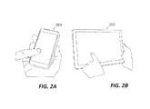
- FIG. 2A and FIG. 2B show two examples of touch surface input devices
- FIG. 3 shows an alternate embodiment of the invention with a different method of connecting components
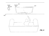
- FIG. 4 shows yet another alternate embodiment of the invention with a different method of connecting components
- FIG. 5 shows still another alternate embodiment of the invention with a subset of the components
- FIG. 6 shows another alternate embodiment of the invention with different configurations for input devices
- FIG. 7 shows two examples of motion sensitive controllers each of which may be used to control a controlled device
- FIG. 8A shows an embodiment of this invention where a virtual touchpad is provided as an additional means of input
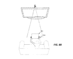
- FIG. 8B shows an exemplary way of configuring the size and perspective of the virtual touchpad by the actions of a user
- FIG. 9A demonstrates how control flows in one embodiment of the invention to enable the control using a controlling device
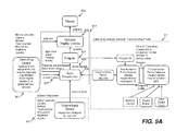
- FIG. 9B a functional block diagram according to one embodiment of the present invention.
- FIG. 10 shows a flowchart demonstrating a signal flow in one embodiment of the invention.
- a (user) input device is a control or controlling device that allows a user to interactively control some or all of the functions of another device.
- a controlling device include: mice, keyboards, joysticks, touch sensitive surfaces, motion controllers (such as the Wii Remote (TM), or PlayStation Move controller, and air mice) and television remote controllers.
- Passive sensors such as video cameras and microphones are also examples of user input devices.
- the controlling device used in the present invention is largely related to a controller including a plurality of inertial sensors, where the controller generates a control signal including sensor signals from the inertial sensors and signals from other sources (e.g., a joystick, an action button or detected positions of a finger in a grid).
- a controller, a controlling device and an input device are interchangeably used herein, a relative term with respect to a controlled device.
- An example of such an input device includes, but may not be limited to, a (video game) controller originally designed for video gaming, a smart phone (e.g., iPhone) with at least one inertial sensor, and a portable computing device producing sensor signals.
- signals are transmitted from an input device to a controlled device in order to cause a change in the behavior of the controlled device or system.
- controlled devices There are many examples of controlled devices.
- Some common examples include various combinations of: video game systems, televisions, digital video recorders (DVRs), DVD players, video cassette recorders, personal computers, laptop computers, tablet computers, home audio systems, cell phones, smart phones, personal music players, graphical displays, and projected graphics systems.
- these controlled devices run modules (e.g., software components) that receive signals from designated input devices, or indirectly process the signals received from the input devices.
- modules e.g., software components
- Some examples of such software components include: applications, games, operating systems, drivers, firmware, kernels, user interface (APls), and etc. These software components are configured to 'listen for and respond to signals of specific types. Broadly, these signals may be categorized as either:
- signals are transmitted from the user input device to a controlled device in order to cause a change in the behavior of the controlled device.
- these abstract signals are provided as a convenience to application programmers who are freed from having to consider a large variety of possible input devices.
- a software component such as a "driver”
- map signals from new alternative input devices providing new (a-priori unknown) categories of input signal into the "listened-for" signals expected by the software components.
- the provision is made by operating system makers or API developers to write and install software components that output signals received from a conceivable source and subsequently use the signals to control existing applications.
- the type of acceptable and expected input may be coupled into existing software components by various means including: (a) its design, (b) through the use of a compiler; or (c) through its dependence upon one or more additional software components (e.g.: a driver, operating system, APIs).
- additional software components e.g.: a driver, operating system, APIs.
- These input devices may not be “touch-surface-like” devices or readily provide “touch-surface-like” signals.
- none of the sensors in an input device directly or obviously provide touch-surface-like signals. Their application and use in lieu of a touch-surface-like input device are therefore not easily implemented or conceived of.
- One aspect of this invention is related to the transformation of sensor signals from an input device into touch-surface-like signals.
- Touch-surface-like signals contain information representing 2D coordinates on a 2D surface.
- an input device is being used by a user to point directly at items shown on a graphical display and configured to estimate the pointed position (e.g., being the intersection of the major axis of the device and the graphical display). Such estimation of the pointed position is referred to as 'drift-free' 'down-the-barrel' pointing.
- Signals for the such drift-free down-the-barrel pointing are a suitable source of 'touch-screen-like' signals because a user can directly correlate the position of orientation of a hand-held device with a position and orientation on a display without the need for graphical feedback (e.g.: a graphical mouse-pointer, crosshair or cursor).
- graphical feedback e.g.: a graphical mouse-pointer, crosshair or cursor
- a mouse in the case of a mouse-like device, a mouse is not capable of providing "down the barrel” pointing signals as mouse-like devices provide a measure of linear velocity in a 2D plane but not an absolute position on 2D plane. Additionally, a mouse provides "mouse-like-signals" received by applications listening for "mouse-like-signals". A source of such "mouse-like-signals" may not directly be used with software listening for "touch-surface-like” signals. Furthermore, a user cannot reliably correlate the physical position of a mouse with a position on a graphical display without the use of graphical feedback (e.g. a mouse-pointer);
- mouse-like-devices also differ in that they are a source of a single stream of 2D values, whereas multi-touch surfaces may generate multiple streams of 2D values.
- One aspect of this invention is the use of a controlling device contemplated in the present invention to provide multi-touch-like signals.
- a point on a plane is determined through the integration over time of angular orientation signals from a gyroscope to obtain a relative measure of the angular position. This measure is subsequently transformed into a point on a 2D plane.
- an input device is configured to overcome the limitation by continuous recalibration with respect to a fixed reference.
- the fixed reference is an electronic compass.
- the fixed reference is an external camera.
- a motion sensitive device can provide usable "touch-surface-like" signals (which, among other attributes, represent absolute positions on a 2D surface) which are qualitatively different from “mouse-like” signals (e.g., 2D velocity).
- "Touch-surface-like" signals have additional characteristics not shared by "mouse-like” signals. These additional characteristics include the ability to distinguish tracing a path along a set of points and individually touching those points in sequence as well as the ability to touch multiple points at once on some devices (a.k.a., multi-touch").
- the device contains an infra-red sensitive camera to detect the location of infra-red LEDs near a graphical display.
- an infra-red sensitive camera to detect the location of infra-red LEDs near a graphical display.
- one embodiment of the present invention does not require the use of a camera in the handheld device or LEDs at the display.
- Examples of external game controllers containing joysticks and buttons such as the Zeemote (TM) are already used to control software components running on touch-screen devices.
- the signals from game controller devices are not used in place of touch-screen-signals, but are instead provided as joystick-like, game-controller-like or direction-pad-like signals and usable only by the subset of software components that explicitly listen for those types of signals.
- one aspect of this invention is the ability to provide an alternative source of touch surface signals that can be used to control all of the functions of software components listening to touch-surface-like signals.
- Another aspect of this invention relates to the transformation of joystick and button signals to replace or augment a touch surface.
- a touch surface is commonly overlaid over a graphical display.
- the position of a touch is highly important, as is the association of the touched position with respect to the frame of the graphical display.
- visual feedback to the user to indicate where on the graphical display an action will occur or has occurred may be missing, neither might there be a provision in an operating system of the device or application to receive the signals from the alternative input device and present them graphically.
- Still another aspect of this invention is the graphical presentation of a pointed position of an alternative input device on the display. This aspect differs from:
- this aspect of the present invention differs from related art concerning the transformation of signals from one type into another in that:
- this invention describes techniques for using a motion controller as an input device for an existing electronic device, the controlled device, running applications previously configured for taking inputs in a different form.
- the signals from the input device may be in a different form from the controlling device.
- the controlled device was designed to host applications that respond to signals from a touch screen or touch screen-like signals.
- the inputs from the motion controller are converted into touch-screen like signals that are then sent to the controlled device or programs being executed in the controlled device to cause the behavior of the controlled device to change or respond thereto.
- FIG. 1 shows an exemplary configuration 100 according to an embodiment of the invention.
- the primary components in this embodiment include a controlling device 101 and a controlled device 102.
- the controlling device 101 provides signals derived from motion sensors enclosed therein and any combination of button sensors, joystick sensors, LEDs, and microphone inputs. These signals are interpreted to control the controlled device 102 which may be composed of several elements including a large display 103 and a touch surface input device 104.
- An exemplary controlling device may be a dedicated controller, a smart phone or other hand-held computing device (e.g., iPhone).
- An exemplary controlled device may be a television, a game console, or a computing device being used to control an application (e.g. a smartphone or a tablet connected to a television).
- the controlling device 101 includes motion sensors (not shown) and none, one or more LEDs that are housed in a body intended to be hand held by a user 109, shown here in his or her living room, seated comfortably on a couch 110.
- the controlling device 101 also contains a communication device and a self-contained power source.
- This communication device is a Bluetooth radio device in one embodiment, but could be replaced by an infra-red communication device or any other form of wireless communication device in alternate embodiments.
- a rechargeable battery is used as the power source.
- the motion signals of the controlling device 101 may be replaced or complemented by signals derived from an external camera that is not attached to the controlling device 101, along with one or more LEDs or other point light sources on the controlling device 101 in view of the camera and the motion sensors in the controlling device 101.
- the controlling device 101 may also be interchangeably referred to herein as a motion controller when describing various embodiments.
- the controlled device 102 is an electronic device configured to execute some modules (e.g., software components) communicating with or controlled by at least a touch-sensitive input device (e.g. a touch screen) or touch-surface-like input device signals (e.g., the touch surface input device 104).
- a touch-sensitive input device e.g. a touch screen
- touch-surface-like input device signals e.g., the touch surface input device 104.
- Examples of the touch-sensitive input devices include resistive or capacitive touch panels over a graphical display. Two examples, a smart phone with a touch screen 201 and a tablet computer 202, are shown in FIG. 2A and FIG. 2B , respectively.
- Touch-surface-like signals are signals describing at least the touched positions or touched points or areas of a 2D plane on a touch-sensitive input device.
- the controlled device 102 may be additionally controlled by any combination of button sensors, keyboard or keypad inputs, joystick sensors, camera or video inputs, microphone inputs, or motion sensors.
- the controlled device 102 includes a large display 103 such as a television, computer monitor, or projected display device along with at least one touch surface input device 104 attached directly to the display 103 by means of a cable 105, such as an HDMI cable.
- the controlled device 302 includes a touch surface device 304 placed into a docking station associated with the display 303 and connected by wire to the display 103 or coupled to a processor therein.
- the controlled device 402 includes a touch surface device 404 that communicates with the display 403 by wireless communication with a receiver/transmitter 405 attached physically to or incorporated into the display 403.
- video signals are transmitted from the touch screen device to the display device.
- the controlled device 502 does not have a touch-screen but still runs applications preconfigured to be controlled by touch-surface-like signals.
- the controlling device may be used as a method to control the applications by transforming its signals (being not touch-screen-like) into touch-screen signals usable to control those applications.
- FIG. 6 shows a controlled system 600 with several different possible configurations of input devices.
- the controlled system 603 includes two devices 601 and 602 with processing units and the capability to run programs or software modules.
- the processing unit(s) are found within the display device, and the touch screen input device.
- the input devices or controlling devices can be any configuration of a webcam 604, a television-embedded camera 605, a second webcam 606 for stereovision, and a motion-sensitive controller 607.
- Signals from the controlling devices 604-607 are used to control software components running in the controlled system 603.
- the software components are configured to listen for signals of particular types or identifiable categories. Examples include:
- the source of the signals may be unknown, but the software components running in the controlled system are configured to "listen-for" or are otherwise controlled by signals of specific types or of identifiable categories.
- signals that are "X-like” are referred to as the signals received by the software components that cause the behavior change of the device running the software components as if the device is controlled by an input device X, but not necessarily originating from the device X.
- One aspect of this invention is to allow one or more software components to be controlled by signals of specific types or of identifiable signal categories:
- the invention permits the remote control of a plurality of software components running on a controlled device, where a touch screen is the primary source of input, and the software components are controllable by the touch screen or touch-surface-like signals.
- the controlling device(s) may be used as a method to control those software components by transforming its signals (being not touch-surface-like) into touch-surface-like signals usable to control those software components.
- transformations include:
- FIG. 7 shows two exemplary motion-sensitive controllers that may be used to control a controlled device as illustrated in FIGS 1-6 .
- the motion sensors are housed internally in the controller and so are not explicitly shown.
- the external affordances of each of the controllers include a microphone behind a grill 701, an analog joystick 702, and several buttons 703.
- Another embodiment of the controllers has a touchpad built into the top surface of the motion controller, allowing a user to slide, rub, tap or provide other touch-based inputs. Such a remote touchpad device could be of any size to be convenient as part of a handheld control device.
- FIG. 8A shows an input device that includes a webcam 801 located on top of a controlled device, a viewing frustrum 802 of the webcam that shows a 2D projection of the field of view of the camera, and a virtual window 803 that is located within that viewing frustrum 802.
- the virtual window 803 is a user-configurable space, within which activity is treated as though occurring on a touchpad. In other words, the virtual window 803 is acting as a virtual touchpad.
- one or more of the fingers (of the user) are tracked. When one finger is extended, the tracked positions in the image plane are projected onto a 2D grid, and the resulting transformed signal is presented to the controlled device as a touch-screen-like signal.
- Such a touch-screen-like signal is able to control applications on the controlled device that were pre-configured for touch-screen inputs.
- the finger When the finger is extended and in the virtual window 803, it is as though the finger is down on the virtual touchpad.
- the virtual touchpad inputs are combined with motion controlled inputs to provide the augmented control signals being used to drive the controlled device. This combination of input types allows a great range of flexibility of inputs from the end user.
- the material elements to this embodiment is the formation of a virtual window 803 and camera-based tracking of an object to create a virtual touchpad that can be used to augment or replace the control signals being used to drive the controlled device.
- FIG. 8B shows one exemplary method by which a user can configure the size and perspective of the virtual window 803 used to create a virtual touchpad, essentially by forming an "L" with both hands 805 to create the virtual touchpad frame 803.
- the size of the frame 803 is simply determined as a rectangle with a fixed ratio between width and height, and the width of the virtual window 803 determined as proportional to the difference in X pixels in the image plane between the corner of the "L"s formed by the user's hands.
- the perspective is determined as proportional to the relative lengths of the forefinger and the thumb of the hands 902 in the image plane.
- the transformation occurs on the controlling device and the output signals thereof are transmitted directly to the controlled device.
- the controlled device is a network-enabled television, being a device capable of receiving and showing video received from an Internet source, or running games, or other networked applications.
- an image of the screen of the touch sensitive input device 104 is shown on the display 103.
- the user 109 then aims the motion controller 101 at the screen in order to specify corresponding 2D positions 107 for the touch screen device. The selection of these positions corresponds to the "Down the Barrel" pointing 106 of the controlling device.
- the controlled system includes two devices 601 and 602 that are capable of running touch-screen-enabled applications.
- the motion controller 607 is used initially to point at the location of each device 601 and 602 and store the angular coordinates.
- the motion controller 607 can point at one device and mark it as the master, which means it will be responsible for driving the content being displayed on the display. From then on, signals derived from pointing at the display will be transformed and sent to the master device alone, even if the master device is not is the one being pointed at. Many possibilities are evident for sharing information back and forth between the two devices, for example transferring data of any kind, including static files or, say, graphical elements that are being accessed and modified on the fly (as in a game).
- the number of devices in the controlled system 603 can exceed two, and it is clear that more than one device can control part of the display 601, as it is also clear that more than one motion controller can be involved in controlling the overall system 603.
- One embodiment of this invention is a method for transforming sensor signals from a motion controller, when used as described above, into touch-surface-like signals.
- the graphical display shows a "pointed position" as an on-screen element (such as a cursor).
- the pointed position follows the motion of the motion device by the transformation of the motion signals from the motion device into points on a 2D plane.
- the controlling device generates sensor signals corresponding to at least three orthogonal accelerometer readings, three orthogonal gyroscope readings, and a compass reading with at least one measurement orthogonal to the gravity vector of the Earth.
- two of the three components of its orientation can be calculated by measuring the direction of the gravity vector using the accelerometers as described in US Patent No.: 7,953,246 , which is hereby incorporated by reference.
- the third component is the rotation around the gravity vector and can be measured directly from the compass. It is understood that these direct measurements of the orientation will not always be available, so the gyroscope sensors provide accurate measurements of angular velocities around each of the three axes over time.
- all three components of orientation can be calculated from the compass if a three-axis compass is present within the controlling device.
- a compass with at least three orthogonal readings is used in place of the gyroscope.
- the readings can be used as a direct estimate of orientation of the controller in the world frame. Errors in the orientation can be reduced by smoothing (averaging) the outputs of multiple readings in order to prevent the user experiencing a jittery cursor when trying to point.
- both the orientation and relative location of the display to the controller can be jointly obtained and updated over time with the use of an external camera in a defined relationship to the display and a light source on the controller visible to that camera as described in co-pending US application serial No.: 13/105,863 which is hereby incorporated by reference.
- ray-casting Given the orientation and relative position of the controller, ray-casting provides a straightforward operation to find the intersection point between the ray originating at the controller and aligned along its orientation with the display.
- relative pointing is used instead of "down-the-barrel" pointing.
- the gyroscope readings from the Motion Controller are mapped directly to relative changes in the location of a cursor on the screen in order to generate the pointed positions, removing the need to have accelerometers, compass sensors, LEDs, or an external camera.
- FIG. 9A demonstrates how control flows in one embodiment of the invention to enable the control using a controlling device 901.
- the controlled device 904 includes the capability to run programs or software modules.
- the controlled device 904 includes processing unit(s) that may be found within the controlled device 904, or in a touch screen input device 910, or both.
- a processing unit is located in a touch screen input device.
- the controlled device 904 is a television containing the processing unit and software components.
- signals from the controlling device 901 are used to control software components 905 running in the controlled device 904.
- the software components 905 are configured to listen for signals of particular types or identifiable categories. Examples include:
- the source of the signals may be unknown, but the software components 905 running in the controlled device are configured to "listen-for" or are otherwise controlled by signals of specific types or of identifiable categories.
- signals that are "X-like” are referred to as the signals received by the software components that cause the behavior change of the device running the software components as if the device is controlled by an input device X, but not necessarily originating from the device X.
- One aspect of this invention is to allow one or more software components to be controlled by signals of specific types or of identifiable signal categories:
- the invention permits the remote control of a plurality of software components running on the controlled device 904, where a touch screen device 910 is the primary source of input, and the software components 905 are controllable by the touch screen device 910 or the touch-surface-like signals therefrom.
- the controlling device 901 may be used to control those software components 905 by transforming its signals 907 (being not touch-surface-like) into touch-surface-like signals 908 usable to control the software components 905.
- a transformation is performed by a module 906 (e.g., a software module or a circuit module), referred to as a transformer herein, to perform make the signals 907 usable to the controlled device 904.
- the transformer 906 is able to perform additional transformations on signals.
- a transformation is specifically related to input signals directly or indirectly derived from the controlling device 901 (including, in some embodiments, signals derived in part from an external camera, but still requiring signals from the controlled device), into output signals of types useable to control the software components and applications running on the controlled device 904.
- transformations include:
- the incoming signals from the controlling device 901 are transformed in the controlled device 904.
- the transformations may not prevent in all cases the control of the software components by other physical devices (e.g., the touch screen device 910), but instead to allow the remote control of the software components by the controlling device 904.
- the remote control may be initially enabled by detecting some event indicating a desire of the user to use such an alternate controller.
- Example possible events include:
- the transformation occurs on the controlling device and the output signals thereof are transmitted directly to the controlled device.
- the controlled device is a network-enabled television, being a device capable of receiving and showing video received from an Internet source, or running games, or other networked applications.
- an image of the screen of the touch sensitive input device 104 is shown on the display 103.
- the user 109 then aims the motion controller 101 at the screen 103 in order to specify corresponding 2D positions 107 for the touch screen device. The selection of these positions corresponds to the "Down the Barrel" pointing 106 of the controlling device 101.
- One embodiment of this invention is a method for transforming sensor signals from a motion controller, when used as described herein, into touch-surface-like signals.
- the graphical display shows a "pointed position" as an on-screen element (such as a cursor).
- the pointed position follows the motion of the motion device by the transformation of the motion signals from the motion device into points on a 2D plane.
- the controlling device generates sensor signals corresponding to at least three orthogonal accelerometer readings, three orthogonal gyroscope readings, and a compass reading with at least one measurement orthogonal to the gravity vector of the Earth.
- two of the three components of its orientation can be calculated by measuring the direction of the gravity vector using the accelerometers as described in US Patent No.: 7,953,246 , which is hereby incorporated by reference.
- the third component is the rotation around the gravity vector and can be measured directly from the compass. It is understood that these direct measurements of the orientation will not always be available, so the gyroscope sensors provide accurate measurements of angular velocities around each of the three axes over time.
- all three components of orientation can be calculated from the compass if a three-axis compass is present within the controlling device.
- a compass with at least three orthogonal readings is used in place of the gyroscope.
- the readings can be used as a direct estimate of orientation of the controller in the world frame. Errors in the orientation can be reduced by smoothing (averaging) the outputs of multiple readings in order to prevent the user experiencing a jittery cursor when trying to point.
- both the orientation and relative location of the display to the controller can be jointly obtained and updated over time with the use of an external camera in a defined relationship to the display and a light source on the controller visible to that camera as described in co-pending US application serial No.: 13/105,863 which is hereby incorporated by reference.
- ray-casting Given the orientation and relative position of the controller, ray-casting provides a straightforward operation to find the intersection point between the ray originating at the controller and aligned along its orientation with the display.
- relative pointing is used instead of "down-the-barrel" pointing.
- the gyroscope readings from the Motion Controller are mapped directly to relative changes in the location of a cursor on the screen in order to generate the pointed positions, removing the need to have accelerometers, compass sensors, LEDs, or an external camera.
- the pointed position on the display device is mapped back to its corresponding position on the touch surface input device when generating touch surface signals.
- the 2D pointed position on the display is used directly to generate a touch-like signal for the software components. Additional transformations and methods of user interaction with the program will be used in alternate embodiments including some subset of the following:
- Volume control pressing and holding a button on the controlling device enters a volume change mode. Rotating the tip of the controller to the right (when viewed from above, looking down) causes the volume to increase. Rotating the tip of the controller to the left (when viewed from above, looking down) causes the volume to decrease.
- Scrolling left and right Pressing and holding a button on the controlling device causes a change in the position of displayed graphical elements.
- Horizontal motions of the tip Motion Controller i.e. the left/right motion of the tip of the controller, when viewed from above, cause the horizontal motion of graphical elements.
- Scrolling up and down Pressing and holding a button causes a change in the position of displayed graphical elements.
- Vertical motions of the tip of the motion controller i.e. the up/down motion of the tip of the controller, when viewed from the side, cause the vertical motion of graphical elements.
- Gesture control If the user makes a motion of a recognizable type, it may generate a corresponding simulated signal for a software event or request such as "Press Home button”, “Scroll Up”, “Save Changes”, “Cancel”, or similar recognizable signals previously defined for the software component.
- Gesture control to touch If the user makes a motion of a recognizable type, it may generate a series of touch-surface signals corresponding to a pre-defined series of pointed positions.
- the series of positions could be defined either by the application, or a previous set of generated touch-signals by the user.
- the user could specify a sequence of pointed positions using one of the single or multi-touch methods detailed above and then specify that that sequence should be associated with motions similar to an example motion or set of motions they provide.
- Audio control If the user makes a recognizable audible signal generate a corresponding simulated software event or request signal such as "Press Home button”, “Scroll Up”, “Save Changes”, “Cancel”, or similar recognizable signals previously defined for the software component.
- Audio Volume Control Use the volume of the audio input from the user to control the output volume of the controlled device. For example, one could decide to match the decibel level of the two.
- Audio to Text Input The transformation of audio signals from the controlling device to provide or replace text input to software components running on the controlled device.
- the transformation is implemented using an existing Text to Speech API, such as the Google Android Text To Speed API.
- Motion to Keyboard-like Input The transformation of motion control signals from the controlling device to provide or replace touch input providing text input to software components running on the controlled device.
- the transformation is from button and motion signals into touch-surface-like signal simulating the selection of the keys shown on an on-screen keyboard.
- Motion to Text Input In another embodiment, the transformation is from button and motion signals into touch-surface-like signal simulating the drawing of words by passing the pointed position through the on-screen symbols representing elements of the chosen word. A disambiguation method is required. In one embodiment existing software components, such as Swype, are used.
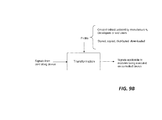
- FIG. 9B shows a functional block diagram according to one embodiment of the present invention.
- the embodiment includes a dynamic choice of a transformation of signals from a controlling device into signals suitable to control the software components on a controlled device based on a Profile, where:
- a profile further represents the dynamic application of the transformation within a specified Context. That is to say, if the Context applies, take the sensor signals from the controlling device, apply the transformation, and provide the resulting signals to software components running on the controlled device.
- a Profile is implemented as programming code, which may (possibly after compilation and linking steps), be executed on the Controlled or controlling device.
- profiles are represented as computer data and so are readily stored, copied, edited, modified, entered into databases or transmitted electronically.
- the functions of the Profile are performed by an additional software component 611 that may load the Profile.
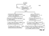
- FIG. 10 shows a flowchart or process 1000 of how a controlling device (e.g., a motion sensitive device) is being used to interact with a controlled device, where signals from the controlling device are mapped to signals acceptable to the controlled device.
- a controlling device e.g., a motion sensitive device
- the mapping or transformation may be performed in accordance with a profile.
- the process 1000 may be implemented in software or a combination of software and hardware.
- the process 1000 checks if a controlling device (e.g., iPhone) is able to communicate with a controlled device (e.g., a smart TV).
- the communication may be conducted in one of many ways, such as WiFI, Bluetooth, or infrared.
- the purpose is to ensure that signals from the controlling device can be received by the controlled device.
- the process 1000 can proceed when the signals from the controlling device can be received by the controlled device.
- a user of the controlling device moves the controlling device around.
- the controlling device includes a set of sensors, at least some of them are inertial sensors that generate motion signals.
- the controlling device is calibrated, such as the measurement of the orientation of the controlling device while the device is pointed at a display of the controlled device. Thus it is initially possible to provide down-the-barrel pointing.
- the sensor signals are transformed according to a transformation.
- the transformation may be implemented in different ways, some of which have been described above.
- One of the functions for the transformation is to transform the sensor signals (along with action signals) to substantially similar to the control signals the controlled device is designed for.
- the controlled device is designed to be controlled by control signals from a touch-screen device or to receive input signals from a touch-screen device.
- the transformation can be designed in one embodiment to transform some or all of the sensor signals to substantially similar to the control signals from the touch-screen device.
- the controlling device can be used to control the controlled device.
- the absolute positions of the controlling device on the 2D surface of the display are calculated at 1010 with respect to a reference frame (e.g., with respect to the display).
- the controlling device may also generate other signals.
- the controlling device can be interfaced with a user to receive a command and an input at 1012.
- the device may also include one or more keys or buttons to activate an action.
- action signals that may also from the controlling device at 1014. Similar to 1008, the action signals are transformed to substantially similar to the action signals the controlled device can accept at 1016.
- both the sensor signals and the action signals are transmitted to the controlled device at the same time depending on how the user desires to control the controlled device. Together with the pointing positions from 1010, the action signals can cause a behavior change to the controlled device at 1018.
- a user needs to scroll a menu with a few items, where the menu is displayed on the controlled device.
- An action e.g., a click
- the controlling device causes the controlling device to send out an action signal that shall be transformed to an action acceptable by the controlled device.
- the controlled device is configured to determine which item in the menu is being selected and shall be activated.
- graphical elements could be removed from the output of the touch-sensitive device and either placed in new configurations (such as to the side of the main display), or removed entirely.
- a game application with a virtual game-pad at the bottom of the screen. If the input controller has a joystick, there may be no need to display the virtual joypad to the user, making a clearer picture for the user, while still allowing the input joystick signals of the controlling device to be mapped to touch-surface signals corresponding to the position of the controls on the original touch-surface device.
- the invention is preferably implemented in software, but can also be implemented in hardware or a combination of hardware and software.
- the invention can also be embodied as computer readable code on a computer readable medium.
- the computer readable medium is any data storage device that can store data which can thereafter be read by a computer system. Examples of the computer readable medium include read-only memory, random-access memory, CD-ROMs, DVDs, magnetic tape, optical data storage devices, and carrier waves.
- the computer readable medium can also be distributed over network-coupled computer systems so that the computer readable code is stored and executed in a distributed fashion.
Landscapes
- Engineering & Computer Science (AREA)
- General Engineering & Computer Science (AREA)
- Theoretical Computer Science (AREA)
- Human Computer Interaction (AREA)
- Physics & Mathematics (AREA)
- General Physics & Mathematics (AREA)
- Position Input By Displaying (AREA)
- Selective Calling Equipment (AREA)
Applications Claiming Priority (2)
| Application Number | Priority Date | Filing Date | Title |
|---|---|---|---|
| US201161500581P | 2011-06-23 | 2011-06-23 | |
| US13/309,326 US20120208639A1 (en) | 2006-07-14 | 2011-12-01 | Remote control with motion sensitive devices |
Publications (2)
| Publication Number | Publication Date |
|---|---|
| EP2538309A2 true EP2538309A2 (fr) | 2012-12-26 |
| EP2538309A3 EP2538309A3 (fr) | 2013-10-09 |
Family
ID=46458191
Family Applications (1)
| Application Number | Title | Priority Date | Filing Date |
|---|---|---|---|
| EP12173321.6A Withdrawn EP2538309A3 (fr) | 2011-06-23 | 2012-06-25 | Télécommande avec dispositifs sensibles au mouvement |
Country Status (3)
| Country | Link |
|---|---|
| EP (1) | EP2538309A3 (fr) |
| JP (1) | JP2013008365A (fr) |
| CN (1) | CN102830795B (fr) |
Cited By (1)
| Publication number | Priority date | Publication date | Assignee | Title |
|---|---|---|---|---|
| DE102023210321A1 (de) * | 2023-10-19 | 2025-04-24 | Jan Wunderlich | Verfahren zum Betreiben eines Sensormoduls für ein Sportgerät, Sensormodul für ein Sportgerät, entsprechendes Sportgerät mit einem Sensormodul sowie Computerprogrammprodukt |
Families Citing this family (25)
| Publication number | Priority date | Publication date | Assignee | Title |
|---|---|---|---|---|
| EP4344163A3 (fr) | 2011-06-05 | 2024-04-24 | Apple Inc. | Systèmes et procédés d'affichage de notifications reçues de multiples applications |
| EP2709060B1 (fr) * | 2012-09-17 | 2020-02-26 | Apple Inc. | Procédé et appareil permettant de déterminer un point de regard fixe sur un objet tridimensionnel |
| WO2014143776A2 (fr) | 2013-03-15 | 2014-09-18 | Bodhi Technology Ventures Llc | Fourniture d'interactions à distance avec un dispositif hôte à l'aide d'un dispositif sans fil |
| CN103218043A (zh) * | 2013-03-28 | 2013-07-24 | 天脉聚源(北京)传媒科技有限公司 | 一种控制取消的方法及装置 |
| CN104216603B (zh) * | 2013-05-31 | 2019-01-15 | 联想(北京)有限公司 | 一种显示方法和电子设备 |
| CN103439127B (zh) * | 2013-07-18 | 2016-02-03 | 深圳市宇恒互动科技开发有限公司 | 惯性输入装置运动质量的测量方法、终端和系统 |
| CN105324736B (zh) * | 2013-07-23 | 2018-09-11 | 英特尔公司 | 触摸式和非触摸式用户交互输入的技术 |
| US20150350146A1 (en) | 2014-05-29 | 2015-12-03 | Apple Inc. | Coordination of message alert presentations across devices based on device modes |
| EP3195098B1 (fr) | 2014-07-21 | 2024-10-23 | Apple Inc. | Interface utilisateur distante |
| US9547419B2 (en) | 2014-09-02 | 2017-01-17 | Apple Inc. | Reduced size configuration interface |
| CN104244059A (zh) * | 2014-09-25 | 2014-12-24 | 苏州乐聚一堂电子科技有限公司 | 活动感应远程音视频互动系统 |
| US10216351B2 (en) * | 2015-03-08 | 2019-02-26 | Apple Inc. | Device configuration user interface |
| US20160358133A1 (en) | 2015-06-05 | 2016-12-08 | Apple Inc. | User interface for loyalty accounts and private label accounts for a wearable device |
| US10887193B2 (en) | 2018-06-03 | 2021-01-05 | Apple Inc. | User interfaces for updating network connection settings of external devices |
| CN109407823B (zh) * | 2018-08-16 | 2020-10-20 | 上海飞智电子科技有限公司 | 电子装置以及触控系统 |
| KR102393717B1 (ko) | 2019-05-06 | 2022-05-03 | 애플 인크. | 전자 디바이스의 제한된 동작 |
| DK201970533A1 (en) | 2019-05-31 | 2021-02-15 | Apple Inc | Methods and user interfaces for sharing audio |
| US11481094B2 (en) | 2019-06-01 | 2022-10-25 | Apple Inc. | User interfaces for location-related communications |
| US11477609B2 (en) | 2019-06-01 | 2022-10-18 | Apple Inc. | User interfaces for location-related communications |
| US12511021B2 (en) | 2020-09-14 | 2025-12-30 | Apple Inc. | Device management user interface |
| US12405717B2 (en) | 2020-10-26 | 2025-09-02 | Apple Inc. | Methods and user interfaces for handling user requests |
| CN113515313B (zh) * | 2020-11-09 | 2024-04-19 | 苏州如林自动化软件科技有限公司 | 运动控制卡配置方法、计算机设备、运动控制方法及系统 |
| CN113365125A (zh) * | 2021-05-31 | 2021-09-07 | 北京字节跳动网络技术有限公司 | 终端的控制方法、装置、终端和存储介质 |
| US12579758B2 (en) | 2022-02-08 | 2026-03-17 | Apple Inc. | Devices, methods, and graphical user interfaces for interacting with virtual objects using hand gestures |
| US12386428B2 (en) | 2022-05-17 | 2025-08-12 | Apple Inc. | User interfaces for device controls |
Citations (1)
| Publication number | Priority date | Publication date | Assignee | Title |
|---|---|---|---|---|
| US7953246B1 (en) | 2006-07-14 | 2011-05-31 | Ailive Inc. | systems and methods for motion recognition with minimum delay |
Family Cites Families (6)
| Publication number | Priority date | Publication date | Assignee | Title |
|---|---|---|---|---|
| JP3264291B2 (ja) * | 1993-05-14 | 2002-03-11 | ソニー株式会社 | コントロールシステム |
| JP2004310528A (ja) * | 2003-04-08 | 2004-11-04 | Mitsumi Electric Co Ltd | 入力装置 |
| US7961909B2 (en) * | 2006-03-08 | 2011-06-14 | Electronic Scripting Products, Inc. | Computer interface employing a manipulated object with absolute pose detection component and a display |
| US8726194B2 (en) * | 2007-07-27 | 2014-05-13 | Qualcomm Incorporated | Item selection using enhanced control |
| CN104219560B (zh) * | 2007-09-18 | 2018-05-25 | 汤姆森许可贸易公司 | 机顶盒的用户界面 |
| KR101564785B1 (ko) * | 2009-09-30 | 2015-10-30 | 엘지전자 주식회사 | 방송 수신 장치의 방송 가이드 화면 제어 방법 및 장치 |
-
2012
- 2012-06-19 JP JP2012137928A patent/JP2013008365A/ja active Pending
- 2012-06-25 CN CN201210210662.2A patent/CN102830795B/zh not_active Expired - Fee Related
- 2012-06-25 EP EP12173321.6A patent/EP2538309A3/fr not_active Withdrawn
Patent Citations (1)
| Publication number | Priority date | Publication date | Assignee | Title |
|---|---|---|---|---|
| US7953246B1 (en) | 2006-07-14 | 2011-05-31 | Ailive Inc. | systems and methods for motion recognition with minimum delay |
Cited By (2)
| Publication number | Priority date | Publication date | Assignee | Title |
|---|---|---|---|---|
| DE102023210321A1 (de) * | 2023-10-19 | 2025-04-24 | Jan Wunderlich | Verfahren zum Betreiben eines Sensormoduls für ein Sportgerät, Sensormodul für ein Sportgerät, entsprechendes Sportgerät mit einem Sensormodul sowie Computerprogrammprodukt |
| DE102023210321B4 (de) * | 2023-10-19 | 2025-09-18 | Jan Wunderlich | Verfahren zum Betreiben eines Sensormoduls für ein Sportgerät, Sensormodul für ein Sportgerät, entsprechendes Sportgerät mit einem Sensormodul sowie Computerprogrammprodukt |
Also Published As
| Publication number | Publication date |
|---|---|
| CN102830795B (zh) | 2016-08-03 |
| CN102830795A (zh) | 2012-12-19 |
| EP2538309A3 (fr) | 2013-10-09 |
| JP2013008365A (ja) | 2013-01-10 |
Similar Documents
| Publication | Publication Date | Title |
|---|---|---|
| EP2538309A2 (fr) | Télécommande avec dispositifs sensibles au mouvement | |
| US9007299B2 (en) | Motion control used as controlling device | |
| US20120208639A1 (en) | Remote control with motion sensitive devices | |
| US11221730B2 (en) | Input device for VR/AR applications | |
| EP3436907B1 (fr) | Système et procédé de contact par survol à distance | |
| US9791918B2 (en) | Breath-sensitive digital interface | |
| US8988342B2 (en) | Display apparatus, remote controlling apparatus and control method thereof | |
| CN104220962B (zh) | 利用触摸手势的手势仿真的设备的命令 | |
| JP5900393B2 (ja) | 情報処理装置、操作制御方法及びプログラム | |
| EP2538308A2 (fr) | Commande basée sur le mouvement d'un dispositif commandé | |
| US20140145955A1 (en) | Smart air mouse | |
| US10203781B2 (en) | Integrated free space and surface input device | |
| KR20130142824A (ko) | 원격 제어 장치 및 그 제어 방법 | |
| KR101339985B1 (ko) | 원격 제어 장치, 디스플레이 장치 및 그 제어 방법 | |
| Tsuchida et al. | Tetraforce: A magnetic-based interface enabling pressure force and shear force input applied to front and back of a smartphone | |
| JP2015525927A (ja) | 表示装置を制御するための方法及び装置 | |
| KR20210010361A (ko) | 원격 호버 터치를 위한 전자 디바이스 및 원격 인터랙션 방법 | |
| JP2009238004A (ja) | ポインティングデバイス | |
| WO2024200680A1 (fr) | Fonctionnement amélioré de pointeur sans contact pendant des activités de saisie à l'aide d'un dispositif informatique | |
| CN202075686U (zh) | 虚拟目标对象的控制设备及其信号处理装置 | |
| Chen et al. | An integrated framework for universal motion control | |
| KR101219292B1 (ko) | 표시부를 구비한 핸드 헬드 기기 및 상기 표시부에 표시되는 객체를 탐색하는 방법 | |
| WO2025040500A1 (fr) | Mouvement de pointeur d'interface utilisateur sans contact pour dispositifs informatiques | |
| CN113220110A (zh) | 显示系统及方法 |
Legal Events
| Date | Code | Title | Description |
|---|---|---|---|
| PUAI | Public reference made under article 153(3) epc to a published international application that has entered the european phase |
Free format text: ORIGINAL CODE: 0009012 |
|
| AK | Designated contracting states |
Kind code of ref document: A2 Designated state(s): AL AT BE BG CH CY CZ DE DK EE ES FI FR GB GR HR HU IE IS IT LI LT LU LV MC MK MT NL NO PL PT RO RS SE SI SK SM TR |
|
| AX | Request for extension of the european patent |
Extension state: BA ME |
|
| PUAL | Search report despatched |
Free format text: ORIGINAL CODE: 0009013 |
|
| AK | Designated contracting states |
Kind code of ref document: A3 Designated state(s): AL AT BE BG CH CY CZ DE DK EE ES FI FR GB GR HR HU IE IS IT LI LT LU LV MC MK MT NL NO PL PT RO RS SE SI SK SM TR |
|
| AX | Request for extension of the european patent |
Extension state: BA ME |
|
| RIC1 | Information provided on ipc code assigned before grant |
Ipc: G06F 3/033 20130101AFI20130830BHEP |
|
| STAA | Information on the status of an ep patent application or granted ep patent |
Free format text: STATUS: THE APPLICATION IS DEEMED TO BE WITHDRAWN |
|
| 18D | Application deemed to be withdrawn |
Effective date: 20140410 |