EP2538469A2 - Batteriepack - Google Patents
Batteriepack Download PDFInfo
- Publication number
- EP2538469A2 EP2538469A2 EP12159294A EP12159294A EP2538469A2 EP 2538469 A2 EP2538469 A2 EP 2538469A2 EP 12159294 A EP12159294 A EP 12159294A EP 12159294 A EP12159294 A EP 12159294A EP 2538469 A2 EP2538469 A2 EP 2538469A2
- Authority
- EP
- European Patent Office
- Prior art keywords
- rib
- battery
- bus bar
- battery pack
- pack according
- Prior art date
- Legal status (The legal status is an assumption and is not a legal conclusion. Google has not performed a legal analysis and makes no representation as to the accuracy of the status listed.)
- Granted
Links
Images


Classifications
-
- H—ELECTRICITY
- H01—ELECTRIC ELEMENTS
- H01M—PROCESSES OR MEANS, e.g. BATTERIES, FOR THE DIRECT CONVERSION OF CHEMICAL ENERGY INTO ELECTRICAL ENERGY
- H01M50/00—Constructional details or processes of manufacture of the non-active parts of electrochemical cells other than fuel cells, e.g. hybrid cells
- H01M50/50—Current conducting connections for cells or batteries
- H01M50/502—Interconnectors for connecting terminals of adjacent batteries; Interconnectors for connecting cells outside a battery casing
-
- H—ELECTRICITY
- H01—ELECTRIC ELEMENTS
- H01M—PROCESSES OR MEANS, e.g. BATTERIES, FOR THE DIRECT CONVERSION OF CHEMICAL ENERGY INTO ELECTRICAL ENERGY
- H01M10/00—Secondary cells; Manufacture thereof
- H01M10/42—Methods or arrangements for servicing or maintenance of secondary cells or secondary half-cells
- H01M10/425—Structural combination with electronic components, e.g. electronic circuits integrated to the outside of the casing
-
- H—ELECTRICITY
- H01—ELECTRIC ELEMENTS
- H01M—PROCESSES OR MEANS, e.g. BATTERIES, FOR THE DIRECT CONVERSION OF CHEMICAL ENERGY INTO ELECTRICAL ENERGY
- H01M10/00—Secondary cells; Manufacture thereof
- H01M10/04—Construction or manufacture in general
- H01M10/0413—Large-sized flat cells or batteries for motive or stationary systems with plate-like electrodes
-
- H—ELECTRICITY
- H01—ELECTRIC ELEMENTS
- H01M—PROCESSES OR MEANS, e.g. BATTERIES, FOR THE DIRECT CONVERSION OF CHEMICAL ENERGY INTO ELECTRICAL ENERGY
- H01M10/00—Secondary cells; Manufacture thereof
- H01M10/04—Construction or manufacture in general
- H01M10/0436—Small-sized flat cells or batteries for portable equipment
-
- H—ELECTRICITY
- H01—ELECTRIC ELEMENTS
- H01M—PROCESSES OR MEANS, e.g. BATTERIES, FOR THE DIRECT CONVERSION OF CHEMICAL ENERGY INTO ELECTRICAL ENERGY
- H01M50/00—Constructional details or processes of manufacture of the non-active parts of electrochemical cells other than fuel cells, e.g. hybrid cells
- H01M50/20—Mountings; Secondary casings or frames; Racks, modules or packs; Suspension devices; Shock absorbers; Transport or carrying devices; Holders
- H01M50/204—Racks, modules or packs for multiple batteries or multiple cells
- H01M50/207—Racks, modules or packs for multiple batteries or multiple cells characterised by their shape
- H01M50/209—Racks, modules or packs for multiple batteries or multiple cells characterised by their shape adapted for prismatic or rectangular cells
-
- H—ELECTRICITY
- H01—ELECTRIC ELEMENTS
- H01M—PROCESSES OR MEANS, e.g. BATTERIES, FOR THE DIRECT CONVERSION OF CHEMICAL ENERGY INTO ELECTRICAL ENERGY
- H01M50/00—Constructional details or processes of manufacture of the non-active parts of electrochemical cells other than fuel cells, e.g. hybrid cells
- H01M50/20—Mountings; Secondary casings or frames; Racks, modules or packs; Suspension devices; Shock absorbers; Transport or carrying devices; Holders
- H01M50/284—Mountings; Secondary casings or frames; Racks, modules or packs; Suspension devices; Shock absorbers; Transport or carrying devices; Holders with incorporated circuit boards, e.g. printed circuit boards [PCB]
-
- H—ELECTRICITY
- H01—ELECTRIC ELEMENTS
- H01M—PROCESSES OR MEANS, e.g. BATTERIES, FOR THE DIRECT CONVERSION OF CHEMICAL ENERGY INTO ELECTRICAL ENERGY
- H01M50/00—Constructional details or processes of manufacture of the non-active parts of electrochemical cells other than fuel cells, e.g. hybrid cells
- H01M50/20—Mountings; Secondary casings or frames; Racks, modules or packs; Suspension devices; Shock absorbers; Transport or carrying devices; Holders
- H01M50/289—Mountings; Secondary casings or frames; Racks, modules or packs; Suspension devices; Shock absorbers; Transport or carrying devices; Holders characterised by spacing elements or positioning means within frames, racks or packs
- H01M50/291—Mountings; Secondary casings or frames; Racks, modules or packs; Suspension devices; Shock absorbers; Transport or carrying devices; Holders characterised by spacing elements or positioning means within frames, racks or packs characterised by their shape
-
- H—ELECTRICITY
- H01—ELECTRIC ELEMENTS
- H01M—PROCESSES OR MEANS, e.g. BATTERIES, FOR THE DIRECT CONVERSION OF CHEMICAL ENERGY INTO ELECTRICAL ENERGY
- H01M50/00—Constructional details or processes of manufacture of the non-active parts of electrochemical cells other than fuel cells, e.g. hybrid cells
- H01M50/20—Mountings; Secondary casings or frames; Racks, modules or packs; Suspension devices; Shock absorbers; Transport or carrying devices; Holders
- H01M50/296—Mountings; Secondary casings or frames; Racks, modules or packs; Suspension devices; Shock absorbers; Transport or carrying devices; Holders characterised by terminals of battery packs
-
- H—ELECTRICITY
- H01—ELECTRIC ELEMENTS
- H01M—PROCESSES OR MEANS, e.g. BATTERIES, FOR THE DIRECT CONVERSION OF CHEMICAL ENERGY INTO ELECTRICAL ENERGY
- H01M50/00—Constructional details or processes of manufacture of the non-active parts of electrochemical cells other than fuel cells, e.g. hybrid cells
- H01M50/50—Current conducting connections for cells or batteries
- H01M50/502—Interconnectors for connecting terminals of adjacent batteries; Interconnectors for connecting cells outside a battery casing
- H01M50/503—Interconnectors for connecting terminals of adjacent batteries; Interconnectors for connecting cells outside a battery casing characterised by the shape of the interconnectors
-
- H—ELECTRICITY
- H01—ELECTRIC ELEMENTS
- H01M—PROCESSES OR MEANS, e.g. BATTERIES, FOR THE DIRECT CONVERSION OF CHEMICAL ENERGY INTO ELECTRICAL ENERGY
- H01M50/00—Constructional details or processes of manufacture of the non-active parts of electrochemical cells other than fuel cells, e.g. hybrid cells
- H01M50/50—Current conducting connections for cells or batteries
- H01M50/502—Interconnectors for connecting terminals of adjacent batteries; Interconnectors for connecting cells outside a battery casing
- H01M50/507—Interconnectors for connecting terminals of adjacent batteries; Interconnectors for connecting cells outside a battery casing comprising an arrangement of two or more busbars within a container structure, e.g. busbar modules
-
- H—ELECTRICITY
- H01—ELECTRIC ELEMENTS
- H01M—PROCESSES OR MEANS, e.g. BATTERIES, FOR THE DIRECT CONVERSION OF CHEMICAL ENERGY INTO ELECTRICAL ENERGY
- H01M50/00—Constructional details or processes of manufacture of the non-active parts of electrochemical cells other than fuel cells, e.g. hybrid cells
- H01M50/50—Current conducting connections for cells or batteries
- H01M50/502—Interconnectors for connecting terminals of adjacent batteries; Interconnectors for connecting cells outside a battery casing
- H01M50/519—Interconnectors for connecting terminals of adjacent batteries; Interconnectors for connecting cells outside a battery casing comprising printed circuit boards [PCB]
-
- H—ELECTRICITY
- H01—ELECTRIC ELEMENTS
- H01M—PROCESSES OR MEANS, e.g. BATTERIES, FOR THE DIRECT CONVERSION OF CHEMICAL ENERGY INTO ELECTRICAL ENERGY
- H01M50/00—Constructional details or processes of manufacture of the non-active parts of electrochemical cells other than fuel cells, e.g. hybrid cells
- H01M50/50—Current conducting connections for cells or batteries
- H01M50/543—Terminals
- H01M50/547—Terminals characterised by the disposition of the terminals on the cells
- H01M50/55—Terminals characterised by the disposition of the terminals on the cells on the same side of the cell
-
- H—ELECTRICITY
- H01—ELECTRIC ELEMENTS
- H01M—PROCESSES OR MEANS, e.g. BATTERIES, FOR THE DIRECT CONVERSION OF CHEMICAL ENERGY INTO ELECTRICAL ENERGY
- H01M50/00—Constructional details or processes of manufacture of the non-active parts of electrochemical cells other than fuel cells, e.g. hybrid cells
- H01M50/50—Current conducting connections for cells or batteries
- H01M50/543—Terminals
- H01M50/552—Terminals characterised by their shape
- H01M50/553—Terminals adapted for prismatic, pouch or rectangular cells
-
- H—ELECTRICITY
- H01—ELECTRIC ELEMENTS
- H01M—PROCESSES OR MEANS, e.g. BATTERIES, FOR THE DIRECT CONVERSION OF CHEMICAL ENERGY INTO ELECTRICAL ENERGY
- H01M10/00—Secondary cells; Manufacture thereof
- H01M10/42—Methods or arrangements for servicing or maintenance of secondary cells or secondary half-cells
- H01M10/425—Structural combination with electronic components, e.g. electronic circuits integrated to the outside of the casing
- H01M2010/4271—Battery management systems including electronic circuits, e.g. control of current or voltage to keep battery in healthy state, cell balancing
-
- Y—GENERAL TAGGING OF NEW TECHNOLOGICAL DEVELOPMENTS; GENERAL TAGGING OF CROSS-SECTIONAL TECHNOLOGIES SPANNING OVER SEVERAL SECTIONS OF THE IPC; TECHNICAL SUBJECTS COVERED BY FORMER USPC CROSS-REFERENCE ART COLLECTIONS [XRACs] AND DIGESTS
- Y02—TECHNOLOGIES OR APPLICATIONS FOR MITIGATION OR ADAPTATION AGAINST CLIMATE CHANGE
- Y02E—REDUCTION OF GREENHOUSE GAS [GHG] EMISSIONS, RELATED TO ENERGY GENERATION, TRANSMISSION OR DISTRIBUTION
- Y02E60/00—Enabling technologies; Technologies with a potential or indirect contribution to GHG emissions mitigation
- Y02E60/10—Energy storage using batteries
-
- Y—GENERAL TAGGING OF NEW TECHNOLOGICAL DEVELOPMENTS; GENERAL TAGGING OF CROSS-SECTIONAL TECHNOLOGIES SPANNING OVER SEVERAL SECTIONS OF THE IPC; TECHNICAL SUBJECTS COVERED BY FORMER USPC CROSS-REFERENCE ART COLLECTIONS [XRACs] AND DIGESTS
- Y02—TECHNOLOGIES OR APPLICATIONS FOR MITIGATION OR ADAPTATION AGAINST CLIMATE CHANGE
- Y02P—CLIMATE CHANGE MITIGATION TECHNOLOGIES IN THE PRODUCTION OR PROCESSING OF GOODS
- Y02P70/00—Climate change mitigation technologies in the production process for final industrial or consumer products
- Y02P70/50—Manufacturing or production processes characterised by the final manufactured product
Definitions
- the present invention relates to a battery pack.
- Secondary batteries refer to batteries capable of being charged or discharged unlike primary batteries that are not chargeable, and the secondary battery has been widely used not only for compact electronic devices such as mobile phones, personal digital assistants (PDAs), notebook computers, etc. but also for energy storage systems.
- a conductor may contact a terminal so that a positive electrode and a negative electrode are short-circuited, which may cause heating or firing of the secondary battery.
- a battery pack comprising a plurality of battery units arranged within a case, each battery unit including first and second electrode tabs, and an insulation plate mounted to the case, the insulation plate having a plurality of first ribs, and a plurality of first bus bars, each first bus bar arranged to cover a respective first rib of the insulation plate, wherein each first bus bar connects a first electrode tab of a first battery unit and a second electrode tab of a second battery unit, the first and second electrode tabs disposed on the first rib which is covered by the first bus bar.
- connection of the battery units is made possible in a manner in which short circuiting between electrode tabs can be prevented by the separation of the ribs, and the covering of the bus bars.
- the battery pack may further comprise a terminal member, and a second bus bar arranged to connect the terminal member to a first electrode tab of one of the plurality of battery units.
- the battery pack may further comprise second ribs arranged perpendicular to the first ribs, wherein each of the first and second bus bars (161, 162) is fixed to a second rib.
- the first ribs may be divided into two groups, and the second ribs may be arranged between the two groups of first ribs.
- Each first bus bar may have a main body portion arranged to cover the first rib, and a cell-balancing portion arranged to cover a portion of the second rib.
- the battery pack may comprise a printed circuit board coupled to the cell-balancing portion of the first bus bar, the printed circuit board arranged to provide battery unit voltage information to a battery management system.
- each first bus bar may comprise at least one side wall arranged to at least partially surround at least one side of a respective first rib.
- the first rib may comprise at least one side wall arranged to face the side wall of the first bus bar.
- the second bus bar may comprise a main body portion covering a first rib, a current-balancing portion covering a portion of the second rib, and a high-current portion to which the terminal member is connected.
- the battery pack may comprise a further terminal member, the terminal members separated by an insulation cover covering the insulation plate.
- the insulation cover may be arranged to spatially separate the first bus bars .
- the first electrode tab of the first battery unit and the second electrode tab of the second battery unit protrude through openings in the insulation plate either side of the first rib on which they are to be disposed, the first and second electrode tabs folded towards each other such that they are supported by the first rib.
- Each first bus bar is attached to the first electrode tab of a first battery unit, the second electrode tab of a second battery unit, and the rib, using a fixing member.
- the first electrode tab of the first battery unit has a different polarity from the second electrode tab of the second battery unit, such that the battery units are serially connected by a first bus bar.
- the first electrode tab of the first battery unit has the same polarity as the second electrode tab of the second battery unit, such that the battery units are connected in parallel by a first bus bar.
- the terms such as “comprise” and/or “comprising” may be construed to denote a certain characteristic, number, step, operation, constituent element, or a combination thereof, but may not be construed to exclude the existence of or a possibility of addition of one or more other characteristics, numbers, steps, operations, constituent elements, or combinations thereof.
- the terms such as “first” and “second” are used herein merely to describe a variety of members, parts, areas, layers, and/or portions, but the constituent elements are not limited by the terms. The terms are used only for the purpose of distinguishing one constituent element from another constituent element.
- like reference numerals refer to like elements throughout.
- FIG. 1 is a perspective view schematically illustrating a battery pack according to an embodiment of the present invention.
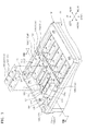
- FIG. 2 is an exploded perspective view schematically illustrating constituent elements of the battery pack of FIG. 1 , except for an insulation cover and a BMS.
- a battery pack may include a case 110, a plurality of battery units 120, an insulation plate 130, a plurality of bus bars 160, a printed circuit board (PCB) 170, an insulation cover 140, and a battery management system (BMS) 150.
- PCB printed circuit board
- BMS battery management system
- the case 110 may have a substantially hexahedral shape with an open upper surface for accommodating the battery units 120.
- the battery units 120 are accommodated in the case 110 to be parallel to one another.
- At least one lateral surface of the case 110 may be open to allow the battery units 120 to be exposed to external air.
- both of lateral surfaces of the case 110 may be open.
- the air introduced through a first opening 111 provided at one open lateral surface of the case 110 may be exhausted outside through a second opening 112 provided at the other open lateral surface by passing through the battery units 120 accommodated in the case 110.
- the case 110 may be formed of an insulation material.
- Each of the battery units 120 has a plate shape and includes a battery cell 123, first and second lead tabs 121 and 122 extending from one side of the battery cell 123, and a frame 125.
- the battery units 120 may be accommodated in the case 110 with first and second lead tabs 121 and 122 being exposed to the outside through the open upper surface of the case 110.
- the battery cell 123 may include, for example, a lithium-ion battery.
- the battery cell 123 may include an electrode assembly (not shown) in which a positive plate, a negative plate, and a plurality of separators interposed therebetween are stacked.
- an electrode assembly (not shown) in which a positive plate, a negative plate, and a plurality of separators interposed therebetween are stacked.
- a plurality of positive plates, negative plates, and separators may be stacked.
- the frame 125 may accommodate the battery cell 123.
- the frame 125 may be formed of an insulation material to secure insulation from the first and second lead tabs 121 and 122.
- the frame 125 may be formed of a polymer resin material such as polyphenylene sulphide (PPS).
- the first and second lead tabs 121 and 122 form interconnection with the outside of the battery cell 123 and may extend from one side of the battery cell 123 to guide current from the battery cell 123 to the outside.
- the first and second lead tabs 121 and 122 may extend toward one side, for example, an upper side, of the frame 125.
- the first and second lead tabs 121 and 122 may include a metal material exhibiting a superior conductivity, for example, aluminium (Al), copper (Cu), nickel (Ni), etc.
- the first and second lead tabs 121 and 122 may have the opposite polarities to each other.
- the first and second lead tabs 121 and 122 may serve as a positive tab and a negative tab, respectively.
- the first and second lead tabs 121 and 122 may be electrically connected to a positive plate (not shown) and a negative plate (not shown) of an electrode assembly (not shown), respectively.
- the first and second lead tabs 121 and 122 having the opposite polarities may be bent in the directions opposite to each other.
- the battery units 120 may be electrically connected using the first and second lead tabs 121 and 122.
- the first lead tab 121 may be bent forward with respect to the direction along which the battery units 120 are arranged, whereas the second lead tab 122 may be bent backward.
- the bending of the first and second lead tabs 121 and 122 may be performed after the provision of a first rib 131 of the insulation plate 130.
- the battery units 120 When the battery units 120 are arranged to form a battery module M, to allow the battery units 120 to be serially connected, suitable for high-voltage applications, the battery units 120 may be arranged with the first and second lead tabs 121 and 122 of one battery unit respectively facing the opposite tabs of a neighbouring battery unit. That is, the neighbouring battery units 120 are arranged so that the left and right sides of the first and second lead tabs 121 and 122 having the opposite polarities may be reversed between each battery unit. A pair of the battery units 120 neighbouring each other may form electrical connection by connecting the first and second lead tabs 121 and 122 of the different battery units 120 bent to face each other. For the electrical connection between the battery units 120, coupling holes 121h and 122h may be formed in the first and second lead tabs 121 and 122.
- the battery units 120 may be arranged in the battery module M such that they are connected in parallel, suitable for high-current applications. This is achieved by arranging the battery units such that first and second lead tabs 121 and 122 of one battery unit respectively face the same tabs of a neighbouring battery unit. That is, the neighbouring battery units 120 are arranged so that the left and right sides of the first and second lead tabs 121 and 122 having the opposite polarities have the same orientation.
- the first and second lead tabs 121 and 122 bent to face each other may be folded on each other on the first rib 131 of the insulation plate 130 and connected by a first bus bar 161 provided on the first and second lead tabs 121 and 122.
- the first bus bar 161 may include a coupling hole 161ah for mechanically coupling the first and second lead tabs 121 and 122 using a fourth fixing member 184.
- any one of the first and second lead tabs 121 and 122 of the battery units 120 located at the outermost position may not be folded on another lead tab.
- the first lead tab 121 of one of the battery units 120 that is located at the foremost position and the second lead tab 122 of one of the battery units 120 that is located at the rearmost position do not have lead tabs to face each other.
- bus bars 160 connected to the first lead tab 121 or the second lead tab 122 bent forward or backward may form a high current flow of a battery pack.
- a second bus bar 162 may be electrically connected to the first lead tab 121
- a third bus bar 163 may be electrically connected to the second lead tab 122.
- the second and third burs bars 162 and 163 may respectively include coupling holes 162ah and 163ah to be mechanically coupled to the first and second lead tabs 121 and 122 using the fourth fixing member 184.
- the bus bars 160 may include a metal material exhibiting superior conductivity, for example, aluminium (Al), copper (Cu), nickel (Ni), etc.
- the bus bars 160 may acquire cell balancing information of the battery units 120.
- the bus bars 160 may be electrically connected to the PCB 170 to acquire information about voltage of each of the battery units 120.
- the bus bars 160 may include coupling holes 161ch, 162ch, and 163ch to be mechanically coupled to the PCB 170 using a fifth fixing member 185.
- the insulation plate 130 may be arranged to cover the open upper portion of the case 110 and mechanically coupled to the case 110 using the first fixing member 181.
- the insulation plate 130 may support the first and second lead tabs 121 and 122 exposed to the upside of the case 110 and bent, and secure insulation between the bus bars 160.
- the insulation plate 130 may include the first rib 131 to stably support the first and second lead tabs 121 and 122 and the bus bars 160, and a second rib 132 to support some of the bus bars 160 and the PCB 170 for acquiring balancing of each battery cell 123.
- the first rib 131 may support the first and second lead tabs 121 and 122 bent forward or backward and the bus bars 160.
- the first rib 131 may form mechanical coupling with the fourth fixing member 184 that passes through the coupling holes 161ah, 162ah, and 163ah of the bus bars 160 and the coupling holes 121h and 122h of the first and second lead tabs 121 and 122.
- the second rib 132 may form mechanical coupling with the fifth fixing member 185 that passes through a coupling hole 170h of the PCB 170 and a coupling hole 160ch formed in the bus bars 160.
- the insulation plate 130 may include first and second terminal members 135 and 136.
- the first and second terminal members 135 and 136 may protrude in one direction to form interconnection with the outside of the battery pack.
- the second bus bar 162 connected to the first lead tab 121 located at the foremost position and the third bus bar 163 connected to the second lead tab 122 located at the rearmost position have the opposite polarities.
- the second bus bar 162 may be a positive pole of the battery module M
- the third bus bar 163 may be a negative pole of the battery module M.
- the second bus bar 162 is connected to the first terminal member 135 and the third bus bar 163 is connected to the second terminal member 136, thereby forming a high current flow of the battery pack.
- the PCB 170 is accommodated on the insulation plate 130 and electrically connected to each of the bus bars 160 so as to sense a voltage of each of the battery units120.
- the PCB 170 may sense a voltage of the battery cell 123 of each of the battery units 120 to monitor whether a voltage difference among the battery cells 123 within an allowable range.
- the voltage sensed by the PCB 170 may be transferred to the BMS 150 via a connector 175 formed on the PCB 170 and used for cell balancing.
- the BMS 150 may include a connector 155 that is connected to the connector 175 of the PCB 170 via a cable (not shown).
- the BMS 150 may compare the voltage of each battery cell 123 with a reference voltage and, when the voltage of each battery cell 123 is greater than the reference voltage, discharge is performed on the battery cell 123 having a voltage exceeding the reference voltage via a discharge path formed corresponding to each battery cell 123, thereby achieving cell balancing.
- the insulation cover 140 may be arranged to cover the insulation plate 130.
- the insulation cover 140 may be arranged in a state in which the first and second lead tabs 121 and 122 and the bus bars 160 are stably coupled via the insulation plate 130 and the PCB 170 is accommodated thereon.
- a second fixing member 182 may be bolt coupled to an upper portion of the insulation plate 130 by passing through a coupling hole 142 formed in the insulation cover 140.
- the insulation cover 140 may prevent short circuit by spatially separating the first and second terminal members 135 and 136 forming the high current flow.
- the insulation cover 140 may include recess portions 145 and 146 for accommodating the first and second lead tabs 121 and 122.
- the insulation cover 140 may prevent a short circuit by spatially separating the bus bars 160 supported on the insulation plate 130.
- a space for accommodating the BMS 150 is provided on an upper surface of the insulation cover 140.
- a third fixing member 183 may be coupled to a coupling hole 143 by passing through the BMS 150.
- a bolt may be used as the third fixing member 183.
- the BMS 150 includes the connector 155 capable of communicating with the PCB 170.
- An opening 141 may be provided in the insulation cover 140 so that the cable connecting the connector 175 of the PCB 170 and the connector 155 of the BMS 150 may pass through the opening 141.
- an outer cover may be further provided on the insulation cover 140 to protect the BMS 150.
- the insulation cover 140 as an inner cover may be coupled to the outer cover through a fixing member such as a bolt.
- FIG. 3 is a perspective view schematically illustrating the insulation plate 130.
- the insulation plate 130 may include a plurality of the first ribs 131 extending in a left and right direction and a plurality of the second ribs 132 extending in the forward and backward direction.
- the second ribs 132 may extend to across the centre of the insulation plate 130.
- the first ribs 131 that extend perpendicularly to the second ribs 132 may be arranged parallel to one another at both sides of the second ribs 132.
- an opening OP through which the first and second lead tabs 121 and 122 pass may be formed.
- the width of the opening OP may be equal to or larger than the width of the first and second lead tabs 121 and 122 so that the first and second lead tabs 121 and 122 may pass through the opening OP.
- the first ribs 131 support the first and second lead tabs 121 and 122.
- the first and second lead tabs 121 and 122 respectively provided at the neighbouring battery units 120 may be exposed to the outside by passing through the openings OP formed at both sides of one of the first ribs 131.
- the first and second lead tabs 121 and 122 passing through the openings OP may be bent in directions facing each other and supported by the first ribs 131.
- the first ribs 131 may simultaneously support the first and second lead tabs 121 and 122 or any one of the first and second lead tabs 121 and 122.
- first ribs 131 may support the bus bars 160 and have a plurality of coupling holes 131h for coupling to the fourth fixing member 184.
- the second rib 132 may extend along a lengthwise direction of the PCB 170 to accommodate the PCB 170.
- the fifth fixing member 185 may be coupled to the second rib 132 by passing through the PCB 170.
- a plurality of coupling holes 132h may be provided in the second rib 132.
- a spacer 137 to guide an accommodation position of the PCB 170 and prevent a movement of the PCB 170 may be provided at both ends of the second rib 132.
- first ribs 131 and the second rib 132 are formed to the same height, the present invention is not limited thereto.
- the second rib 132 may extend as high as the height of the upper surface of the spacer 137 to be higher than the first ribs 131.
- the first and second terminal members 135 and 136 may protrude upwardly to induce current from the battery pack to the outside.
- the first and second terminal members 135 and 136 may include a metal material exhibiting superior conductivity.
- the first and second terminal members 135 and 136 may include a material such as aluminium (Al), copper (Cu), nickel (Ni), etc.
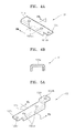
- FIGS. 4A through 6B illustrate the bus bars 160 according to an embodiment of the present invention.
- FIG. 4A is a perspective view of the first bus bar 161.
- FIGS. 5A and 6A are perspective views of the second and third bus bars 162 and 163.
- FIGS. 4B , 5B, and 6B are cross-sectional views taken along lines IVb-IVb, Vb-Vb, and VIb-VIb of FIGS. 4A, 5A , and 6A , respectively.
- the first bus bar 161 may include a main body portion 161a, and a cell balancing portion 161c.
- the main body portion 161a may include an upper surface and side walls extending downwardly from both sides of the upper surface, to wrap the first and second lead tabs 121 and 122 bent on the first rib 131.
- the upper surface of the main body portion 161a may contact the bent first and second lead tabs 121 and 122 supported by the first rib 131, and the side walls provided at both sides of the main body portion 161a may respectively cover the first and second lead tabs 121 and 122. Only one side wall need be present however, which at least partially surrounds one side of the first rib 131.
- the first rib 131 comprises at least one side wall which is arranged to face a respective side wall of the first bus bar 161, as illustrated in FIG. 10 .
- the presence of the side walls of both the first rib 131 and the first bus bar 161 facilitates securing of the position of the first and second lead tabs 121 122 between the first rib 131 and the first bus bar 161.
- the main body portion 161a may be coupled to the first rib 131 with the bent first and second lead tabs 121 and 122 interposed therebetween. To this end, the main body portion 161a may include the coupling hole 161ah formed at a position corresponding to the coupling hole 131h that is formed in the first rib 131.
- the cell balancing portion 161c may protrude from one end of the main body portion 161a to transmit voltage information of the battery cell 123 included in each of the battery units 120 to the PCB 170. To this end, the cell balancing portion 161c may include the coupling hole 161ch for connection to the PCB 170.
- the second bus bar 162 may include a main body portion 162a, a cell balancing portion 162c, and a high current portion 162d.
- the main body portion 162a may include an upper surface and a side wall extending downwardly from one side of the upper surface to wrap the first lead tab 121 bent on the first rib 131.
- the upper surface of the main body portion 162a may contact the bent first lead tab 121 supported by the first rib 131, and the side wall may partially cover the first lead tab 121 that is not placed on the first rib 131.
- the main body portion 162a may be coupled to the first rib 131 with the bent first lead tab 121 interposed therebetween. To this end, the main body portion 162a may include the coupling hole 162ah formed at a position corresponding to the coupling hole 131h that is formed in the first rib 131.
- the cell balancing portion 162c may protrude from one end of the main body portion 162a to transmit voltage information of the battery cell 123 included in each of the battery units 120 to the PCB 170. To this end, the cell balancing portion 162c may include the coupling hole 162ch for connection to the PCB 170.
- the high current portion 162d may protrude from the other end of the main body portion 162a and include a through hole 162dh for coupling to the first terminal member 135. As the first terminal member 135 is inserted into the through hole 162dh, the high current portion 162d may be electrically connected to the first terminal member 135 in contact with the same.
- the third bus bar 163 may include a main body portion 163a, a cell balancing portion 163c, and a high current portion 163d.
- the main body portion 163a may include an upper surface and a side wall extending downwardly from one side of the upper surface to wrap the second lead tab 122 bent on the first rib 131.
- the upper surface of the main body portion 163a may contact the bent second lead tab 122 supported by the first rib 131, and the side wall may partially cover the second lead tab 122 that is not placed on the first rib 131.
- the main body portion 163a may be coupled to the first rib 131 with the bent second lead tab 122 interposed therebetween. To this end, the main body portion 163a may include the coupling hole 163ah formed at a position corresponding to the coupling hole 131h that is formed in the first rib 131.
- the cell balancing portion 163c may protrude from one end of the main body portion 163a to transmit voltage information of the battery cell 123 included in each of the battery units 120 to the PCB 170. To this end, the cell balancing portion 163c may include the coupling hole 163ch for connection to the PCB 170.
- the high current portion 163d may protrude from the other end of the main body portion 163a and include a through hole 163dh for coupling to the second terminal member 136. As the second terminal member 136 is inserted into the through hole 163dh, the high current portion 163d may be electrically connected to the second terminal member 136 in contact with the same.
- the present invention is not limited thereto.
- the cell balancing portions 161c, 162c, and 163c may be formed to be higher than the main body portions 161a, 162a, and 163a according to the height of the second rib 132.
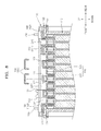
- FIG. 7 is a perspective view schematically illustrating the insulation plate 130 and the bus bars 160 arranged in an upper portion of the case 110 when the battery units 120 are accommodated in the case 110.
- FIG. 8 is a cross-sectional view taken along line VIII-VIII of FIG. 7 .
- FIG. 9 is a perspective view schematically illustrating a state in which the first and second lead tabs 121 and 122 and the bus bars 160 are coupled to each other on the insulation plate 130.
- FIG. 10 is a cross-sectional view taken along line X-X of FIG. 9 .
- the insulation plate 130 may be arranged on the case 110 such that the openings OP1 and OP2 can correspond to the first and second lead tabs 121 and 122 extending from the battery unit 120.
- the first and second lead tabs 121 and 122 extending from the neighbouring battery units 120 may be exposed to the outside by passing through the openings OP1 and OP2 provided at both sides of the first rib 131.
- the first and second lead tabs 121 and 122 exposed to the outside may be bent toward each other on the first rib 131.
- the bent first and second lead tabs 121 and 122 are folded over each other on the first rib 131, thereby serially connecting the neighbouring battery units 120.
- the hole 121h formed in the first lead tab 121 and the hole 122h formed in the second lead tab 122 may be aligned with the hole formed in the first rib 131.
- the first lead tab 121 extending through the opening OP1 provided at the foremost position is bent forward and accommodated on the first rib 131.
- the second lead tab 122 extending through an opening OP5 provided at the rearmost position is bent backward and accommodated on the first rib 131.
- the bus bars 160 may be accommodated on the first rib 131.
- the bus bars 160 may be arranged on the first lead tab 121 and/or the second lead tab 122 that are accommodated on the first rib 131.
- the cell balancing portion 160c of each of the bus bars 160 may be accommodated on the second rib 132.
- the hole 160ah formed in each of the bus bars 160 may be aligned with the holes 121h and 122h of the first and second lead tabs 121 and 122 and the hole of the first rib 131.
- the first bus bar 161 may be accommodated on the first and second lead tabs 121 and 122 folded over each other on the first rib 131
- the second bus bar 162 may be accommodated on the first lead tab 121 that is accommodated on the first rib 131
- the third bus bar 163 may be accommodated on the second lead tab 122 that is accommodated on the first rib 131.
- the high current portions 162d and 163d of second and third bus bars 162 and 163 may be coupled to the first and second terminal members 135 and 136, respectively.
- the first bus bar 161 may be fixed on the first rib 131 by the fourth fixing member 184.
- the fourth fixing member 184 may be coupled to the first rib 131 by passing through the hole 161ah formed in the first bus bar 161 and the holes 121h and 122h formed in the first and second lead tabs 121 and122.
- a bolt may be used as the fourth fixing member 184.
- the second bus bar 162 may be fixed on the first rib 131 using the fourth fixing member 184.
- the fourth fixing member 184 may be coupled to the first rib 131 by passing through the hole 162ah formed in the second bus bar 162 and the hole 121h formed in the first lead tab 121.
- the third bus bar 163 may be fixed on the first rib 131 using the fourth fixing member 184.
- the side walls of the bus bars 160 extend downwardly, i.e. toward the first lead tab 121 and/or the second lead tab 122, and cover the first lead tab 121 and/or the second lead tab 122, so that the bus bars 160 may protect the first and second lead tabs 121 and 122. since the first ribs 131 formed on the insulation plate 130 are separated from each other and the first and second lead tabs 121 and 122 and the bus bars 160 are coupled to the first ribs 131using the fourth fixing member 184, the connection there between may be stably maintained and short-circuits between the bus bars 160 and between the first and second lead tabs 121 and 122 may be prevented.
- FIG. 11 is a perspective view schematically illustrating a state in which the PCB 170 is accommodated on the bus bars 160.
- the PCB 170 is arranged to cover the cell balancing portion 160c of the bus bars 160 accommodated on the second rib 132.
- the cell balancing portion 160c may be electrically connected to a lower surface of the PCB 170 in contact with the same.
- the PCB 170 may be fixed on the insulation plate 130 using the fifth fixing member 185.
- the hole 160ch formed in the cell balancing portion 160c may be aligned with the hole 132h of the second rib 132.
- the fifth fixing member 185 may be coupled to the second rib 132 by passing through the PCB 170 and the cell balancing portion 160c.
- the voltage information of the battery cell 123 acquired through each cell balancing portion 160c is converged on the connector 175 via a wiring formed in the PCB 170 and is transferred to the BMS 150 via the cable connected to the connector 175, as described above.
Landscapes
- Chemical & Material Sciences (AREA)
- Chemical Kinetics & Catalysis (AREA)
- Electrochemistry (AREA)
- General Chemical & Material Sciences (AREA)
- Engineering & Computer Science (AREA)
- Manufacturing & Machinery (AREA)
- Microelectronics & Electronic Packaging (AREA)
- Connection Of Batteries Or Terminals (AREA)
- Battery Mounting, Suspending (AREA)
Applications Claiming Priority (2)
| Application Number | Priority Date | Filing Date | Title |
|---|---|---|---|
| US201161500341P | 2011-06-23 | 2011-06-23 | |
| US13/243,457 US8609276B2 (en) | 2011-06-23 | 2011-09-23 | Battery pack |
Publications (3)
| Publication Number | Publication Date |
|---|---|
| EP2538469A2 true EP2538469A2 (de) | 2012-12-26 |
| EP2538469A3 EP2538469A3 (de) | 2013-12-18 |
| EP2538469B1 EP2538469B1 (de) | 2016-09-14 |
Family
ID=45887932
Family Applications (1)
| Application Number | Title | Priority Date | Filing Date |
|---|---|---|---|
| EP12159294.3A Active EP2538469B1 (de) | 2011-06-23 | 2012-03-13 | Batteriepack |
Country Status (4)
| Country | Link |
|---|---|
| US (1) | US8609276B2 (de) |
| EP (1) | EP2538469B1 (de) |
| KR (2) | KR20130023059A (de) |
| CN (1) | CN102842695B (de) |
Cited By (12)
| Publication number | Priority date | Publication date | Assignee | Title |
|---|---|---|---|---|
| EP2645450A1 (de) * | 2012-03-26 | 2013-10-02 | Leclanché S.A. | Zuverlässige und effiziente Verbindung für Batterien |
| EP2757611A1 (de) * | 2013-01-18 | 2014-07-23 | Samsung SDI Co., Ltd. | Batteriemodul |
| EP3131138A4 (de) * | 2014-05-29 | 2017-07-05 | LG Chem, Ltd. | Batteriemodul mit isolierendem formteil |
| EP3291333A4 (de) * | 2015-07-13 | 2018-03-07 | LG Chem, Ltd. | Sammelschienenstruktur |
| EP3736874A1 (de) * | 2019-05-10 | 2020-11-11 | Andreas Stihl AG & Co. KG | Akkupack, bearbeitungssystem und verfahren zur herstellung eines akkupacks |
| EP3671901A4 (de) * | 2017-11-06 | 2020-11-25 | LG Chem, Ltd. | Batteriemodul mit busschienenanordnung |
| EP3758092A1 (de) * | 2019-06-26 | 2020-12-30 | TE Connectivity Germany GmbH | Trägerstruktur, zellenkontaktierungssystem und herstellungsverfahren |
| CN112310567A (zh) * | 2019-10-21 | 2021-02-02 | 宁德时代新能源科技股份有限公司 | 连接组件、电池模块、电池组以及使用电池模块作为电源的设备 |
| CN112467188A (zh) * | 2020-11-30 | 2021-03-09 | 远景动力技术(江苏)有限公司 | 电池模组的装配方法 |
| DE102020117902A1 (de) | 2020-07-07 | 2022-01-13 | Otto-Von-Guericke-Universität Magdeburg | Verbindungsanordnung und elektrischer Energiespeicher |
| EP3902057A4 (de) * | 2019-12-27 | 2022-04-06 | Contemporary Amperex Technology Co., Limited | Separatorplattenkomponente, batteriemodul, batteriepack, vorrichtung und herstellungsverfahren |
| WO2024121484A1 (fr) * | 2022-12-07 | 2024-06-13 | Safran Electrical & Power | Ensemble de cellules d'un élément accumulateur d'énergie et procédé d'assemblage dudit ensemble |
Families Citing this family (68)
| Publication number | Priority date | Publication date | Assignee | Title |
|---|---|---|---|---|
| WO2013054727A1 (ja) * | 2011-10-13 | 2013-04-18 | 株式会社ケーヒン | 電源制御装置 |
| TWI441578B (zh) * | 2012-01-11 | 2014-06-11 | Delta Electronics Inc | 電路板組合 |
| WO2015103548A1 (en) | 2014-01-03 | 2015-07-09 | Quantumscape Corporation | Thermal management system for vehicles with an electric powertrain |
| WO2014171559A1 (ko) * | 2013-04-15 | 2014-10-23 | 주식회사 엘지화학 | 신규한 구조의 전지모듈 및 이를 포함하는 전지팩 |
| KR101636444B1 (ko) * | 2013-06-20 | 2016-07-05 | 주식회사 엘지화학 | 전지모듈 및 이를 포함하는 전지팩 |
| KR20160030278A (ko) * | 2013-08-09 | 2016-03-16 | 애플 인크. | 배터리 관리 시스템, 다수의 셀 서브세트 및 밀폐형 케이싱을 갖는 배터리 |
| US9831482B2 (en) | 2013-09-06 | 2017-11-28 | Johnson Controls Technology Company | Battery module lid system and method |
| KR101636380B1 (ko) * | 2013-09-26 | 2016-07-05 | 주식회사 엘지화학 | 전압 센싱 어셈블리 및 이를 포함하는 전지모듈 |
| WO2015061443A1 (en) * | 2013-10-25 | 2015-04-30 | Quantumscape Corporation | Thermal and electrical management of battery packs |
| US9397328B2 (en) * | 2014-01-22 | 2016-07-19 | Ford Global Technologies, Llc | Flexible busbar holder for welded cells |
| KR101523588B1 (ko) * | 2014-05-08 | 2015-05-28 | 안동대학교 산학협력단 | 2차 전지 어셈블리 |
| KR101737489B1 (ko) | 2014-06-05 | 2017-05-18 | 주식회사 엘지화학 | 터미널 볼트의 토크 지지 구조가 개선된 배터리 팩 |
| JP2015230892A (ja) * | 2014-06-09 | 2015-12-21 | ソニー株式会社 | 電池モジュール、蓄電装置、蓄電システム、電子機器、電動車両および電力システム |
| CN104659320B (zh) * | 2014-06-25 | 2017-09-15 | 湖北骆驼蓄电池研究院有限公司 | 电芯极耳连接装置及方法 |
| US9705121B2 (en) * | 2014-08-18 | 2017-07-11 | Johnson Controls Technology Company | Lead frame for a battery module |
| US9834114B2 (en) | 2014-08-27 | 2017-12-05 | Quantumscape Corporation | Battery thermal management system and methods of use |
| US9520587B2 (en) | 2014-09-30 | 2016-12-13 | Johnson Controls Technology Company | Bus bar assembly carrier |
| CN104377325B (zh) * | 2014-11-04 | 2017-07-14 | 惠州市德赛电池有限公司 | 一种车载启动电源 |
| KR101640100B1 (ko) * | 2014-11-10 | 2016-07-18 | 한국단자공업 주식회사 | 배터리모듈용 직렬연결장치 |
| KR102379562B1 (ko) | 2015-02-25 | 2022-03-28 | 삼성에스디아이 주식회사 | 배터리 팩 |
| KR102379560B1 (ko) * | 2015-02-25 | 2022-03-28 | 삼성에스디아이 주식회사 | 배터리 팩 |
| KR102381777B1 (ko) * | 2015-02-25 | 2022-04-01 | 삼성에스디아이 주식회사 | 배터리 팩 |
| KR102384022B1 (ko) * | 2015-02-25 | 2022-04-07 | 삼성에스디아이 주식회사 | 배터리 팩 |
| USD763193S1 (en) | 2015-06-02 | 2016-08-09 | Johnson Controls Technology Controls | Bus bar carrier for lithium ion battery module |
| KR102397218B1 (ko) * | 2015-08-27 | 2022-05-12 | 삼성에스디아이 주식회사 | 배터리 팩 |
| CN105244467B (zh) * | 2015-09-16 | 2017-09-29 | 浙江超威创元实业有限公司 | 一种压接式动力电池组装结构、组装方法及电动车 |
| WO2017117720A1 (zh) * | 2016-01-05 | 2017-07-13 | 宁德时代新能源科技股份有限公司 | 电池模组及电池包 |
| WO2017138733A1 (ko) * | 2016-02-12 | 2017-08-17 | 주식회사 엘지화학 | 통합형 카트리지 및 이를 포함하는 배터리 팩 |
| KR102012403B1 (ko) * | 2016-09-13 | 2019-08-20 | 주식회사 엘지화학 | 통합형 카트리지 및 이를 포함하는 배터리 팩 |
| KR102082903B1 (ko) | 2016-02-22 | 2020-02-28 | 주식회사 엘지화학 | 배터리 모듈, 이러한 배터리 모듈을 포함하는 배터리 팩 및 이러한 배터리 팩을 포함하는 자동차 |
| KR102119183B1 (ko) * | 2016-08-18 | 2020-06-04 | 주식회사 엘지화학 | 배터리 모듈 |
| KR102210886B1 (ko) | 2016-09-30 | 2021-02-02 | 삼성에스디아이 주식회사 | 배터리 팩 |
| DE102016222083A1 (de) * | 2016-11-10 | 2018-05-17 | Robert Bosch Gmbh | Batteriemodul, Deckelelement eines Batteriemoduls, Verfahren zur Herstellung derselben und Batterie |
| WO2018117126A1 (ja) * | 2016-12-19 | 2018-06-28 | カルソニックカンセイ株式会社 | 組電池 |
| CN110392943B (zh) * | 2017-03-07 | 2022-11-22 | 远景Aesc日本有限公司 | 电池组以及电池组的制造方法 |
| KR102158363B1 (ko) * | 2017-04-07 | 2020-09-21 | 주식회사 엘지화학 | 전극 리드간 연결 구조를 개선한 배터리 모듈 및 그 제조방법 |
| KR102157377B1 (ko) * | 2017-05-25 | 2020-09-17 | 주식회사 엘지화학 | 배터리 모듈, 이를 포함하는 배터리 팩 및 배터리 모듈 생산 방법 |
| CN109301634B (zh) * | 2017-07-24 | 2020-06-19 | 莫仕连接器(成都)有限公司 | 电池连接模块 |
| CN109428026A (zh) * | 2017-08-31 | 2019-03-05 | 宁德时代新能源科技股份有限公司 | 电池模组 |
| KR102270266B1 (ko) * | 2017-11-30 | 2021-06-28 | 주식회사 엘지에너지솔루션 | 버스바 어셈블리를 구비한 배터리 모듈 |
| JP7081237B2 (ja) * | 2018-03-16 | 2022-06-07 | 株式会社オートネットワーク技術研究所 | 接続モジュール、および蓄電モジュール |
| US10971786B2 (en) * | 2018-04-13 | 2021-04-06 | GM Global Technology Operations LLC | Isolative shield with positional control features for welded flexible cell tabs in an HV battery cell stack |
| CN110752340B (zh) * | 2018-07-23 | 2021-02-09 | 宁德时代新能源科技股份有限公司 | 采样组件及电池模组 |
| KR102366138B1 (ko) | 2018-12-06 | 2022-02-22 | 주식회사 엘지에너지솔루션 | 전지 모듈 |
| US20200212381A1 (en) * | 2018-12-26 | 2020-07-02 | GM Global Technology Operations LLC | Method and tool for combing and locating flexible cell tabs during a battery manufacturing process |
| CN109786611B (zh) * | 2019-02-02 | 2024-01-16 | 广东微电新能源有限公司 | 电池装置以及电子设备 |
| WO2020180827A1 (en) * | 2019-03-01 | 2020-09-10 | Ted Thomas | Stackable battery bussing system |
| KR102789863B1 (ko) * | 2019-09-02 | 2025-03-31 | 주식회사 엘지에너지솔루션 | 커넥터 |
| CN110534678A (zh) * | 2019-09-19 | 2019-12-03 | 安徽超稳动力节能科技有限公司 | 电芯组合及采用该电芯组合的电池组件 |
| KR102795269B1 (ko) | 2019-10-07 | 2025-04-15 | 주식회사 엘지에너지솔루션 | 전지셀의 리드와 버스바의 기계적 연결구조를 갖는 전지모듈 |
| CN114424395B (zh) * | 2020-01-08 | 2024-06-25 | 株式会社Lg新能源 | 电池组、电子装置和车辆 |
| KR102812829B1 (ko) * | 2020-03-05 | 2025-05-23 | 주식회사 엘지에너지솔루션 | 이동 및 조립이 편의성이 증대된 구조 및 안전성이 향상된 구조를 갖는 배터리 팩 |
| CN111129412B (zh) * | 2020-03-31 | 2020-12-29 | 江苏时代新能源科技有限公司 | 连接组件、电池模块、装置以及连接组件的制造方法 |
| KR102821825B1 (ko) | 2020-07-22 | 2025-06-16 | 주식회사 엘지에너지솔루션 | 전극 리드와 전압 센싱부재 간의 연결을 단순화한 배터리 모듈 및 이를 포함하는 배터리 팩 |
| KR102866740B1 (ko) | 2020-08-11 | 2025-09-29 | 주식회사 엘지에너지솔루션 | 조립성이 개선된 배터리 모듈 및 이를 포함하는 배터리 팩 |
| KR102941254B1 (ko) * | 2020-11-04 | 2026-03-18 | 주식회사 엘지에너지솔루션 | 전지 모듈 및 이를 포함하는 전지팩 |
| CN113097626B (zh) * | 2021-03-30 | 2023-07-21 | 东莞新能安科技有限公司 | 电池包、储能系统及用电设备 |
| KR102934825B1 (ko) | 2021-08-18 | 2026-03-04 | 에스케이온 주식회사 | 배터리모듈 |
| KR102669979B1 (ko) * | 2021-12-02 | 2024-05-29 | 삼성에스디아이 주식회사 | 배터리 팩 |
| CN118985062A (zh) * | 2022-04-14 | 2024-11-19 | Cps 科技控股有限公司 | 智能电池系统、用于智能电池系统的部件、制造和操作智能电池系统及其部件的方法 |
| EP4459763A4 (de) * | 2022-06-09 | 2025-05-07 | LG Energy Solution, Ltd. | Sammelschienenrahmenanordnung und batteriemodul damit |
| KR102885314B1 (ko) * | 2022-10-11 | 2025-11-13 | 주식회사 엘지에너지솔루션 | Bms 어셈블리, 이를 포함하는 배터리 모듈 및 배터리 팩 |
| JP2024114454A (ja) * | 2023-02-13 | 2024-08-23 | プライムプラネットエナジー&ソリューションズ株式会社 | 蓄電モジュール |
| KR20240166897A (ko) | 2023-05-18 | 2024-11-26 | 주식회사 엘지에너지솔루션 | 배터리 어셈블리 및 이를 포함하는 배터리 팩 |
| KR102855330B1 (ko) * | 2023-06-15 | 2025-09-03 | 주식회사 엘지에너지솔루션 | 배터리 셀 어셈블리 |
| KR20250008362A (ko) * | 2023-07-07 | 2025-01-14 | 주식회사 엘지에너지솔루션 | 셀 스택 조립체 |
| DE102023208505A1 (de) * | 2023-09-04 | 2025-03-06 | Robert Bosch Gesellschaft mit beschränkter Haftung | Batteriemodul und Verfahren zur Herstellung eines solchen |
| EP4621957A1 (de) * | 2024-03-19 | 2025-09-24 | Eve Energy Co., Ltd. | Batteriepack |
Family Cites Families (12)
| Publication number | Priority date | Publication date | Assignee | Title |
|---|---|---|---|---|
| US4808495A (en) | 1987-11-09 | 1989-02-28 | Perma Power Electronics, Inc. | Shock-protected battery cover assembly |
| JP3271495B2 (ja) | 1995-10-24 | 2002-04-02 | 松下電器産業株式会社 | 組蓄電池 |
| JP3812063B2 (ja) | 1997-06-03 | 2006-08-23 | 日産自動車株式会社 | 蓄電池収容装置 |
| US7118827B2 (en) * | 2003-08-06 | 2006-10-10 | Delphi Technologies, Inc. | Battery assembly and method of making same |
| WO2007121445A2 (en) * | 2006-04-18 | 2007-10-25 | Securaplane Technologies, Inc. | Battery busing scheme |
| JP5288853B2 (ja) * | 2008-03-24 | 2013-09-11 | 株式会社東芝 | 電池パック |
| CN101651186A (zh) * | 2008-08-15 | 2010-02-17 | 深圳市比克电池有限公司 | 一种电池极耳与盖板的装配方法 |
| JP5155772B2 (ja) * | 2008-08-19 | 2013-03-06 | 三菱重工業株式会社 | バッテリパック構造 |
| KR101552904B1 (ko) | 2008-12-08 | 2015-09-14 | 삼성에스디아이 주식회사 | 이차 전지 및 이를 이용한 전지 모듈 |
| KR20100067464A (ko) | 2008-12-11 | 2010-06-21 | 삼성에스디아이 주식회사 | 전지 모듈 |
| PL386823A1 (pl) * | 2008-12-16 | 2010-06-21 | Impact Automotive Technologies Spółka Z Ograniczoną Odpowiedzialnością | Sposób łączenia biegunów ogniw elektrycznych oraz złącze biegunów ogniw elektrycznych |
| KR20110024954A (ko) | 2009-09-03 | 2011-03-09 | 삼성전자주식회사 | 냉각용 유로를 갖는 이차 전지 모듈 |
-
2011
- 2011-09-23 US US13/243,457 patent/US8609276B2/en active Active
-
2012
- 2012-03-07 CN CN201210058030.9A patent/CN102842695B/zh active Active
- 2012-03-13 EP EP12159294.3A patent/EP2538469B1/de active Active
- 2012-06-25 KR KR1020120068170A patent/KR20130023059A/ko not_active Ceased
-
2016
- 2016-10-31 KR KR1020160143691A patent/KR101835582B1/ko active Active
Non-Patent Citations (1)
| Title |
|---|
| None |
Cited By (20)
| Publication number | Priority date | Publication date | Assignee | Title |
|---|---|---|---|---|
| EP2645450A1 (de) * | 2012-03-26 | 2013-10-02 | Leclanché S.A. | Zuverlässige und effiziente Verbindung für Batterien |
| EP2757611A1 (de) * | 2013-01-18 | 2014-07-23 | Samsung SDI Co., Ltd. | Batteriemodul |
| US9799872B2 (en) | 2013-01-18 | 2017-10-24 | Samsung Sdi Co., Ltd. | Battery module |
| EP3131138A4 (de) * | 2014-05-29 | 2017-07-05 | LG Chem, Ltd. | Batteriemodul mit isolierendem formteil |
| US10505161B2 (en) | 2014-05-29 | 2019-12-10 | Lg Chem, Ltd. | Battery module having molding part for insulating |
| EP3291333A4 (de) * | 2015-07-13 | 2018-03-07 | LG Chem, Ltd. | Sammelschienenstruktur |
| US10446878B2 (en) | 2015-07-13 | 2019-10-15 | Lg Chem, Ltd. | Bus bar structure with fuse case between bus bars |
| US11223092B2 (en) | 2017-11-06 | 2022-01-11 | Lg Chem, Ltd. | Battery module comprising bus bar assembly |
| EP3671901A4 (de) * | 2017-11-06 | 2020-11-25 | LG Chem, Ltd. | Batteriemodul mit busschienenanordnung |
| EP3736874A1 (de) * | 2019-05-10 | 2020-11-11 | Andreas Stihl AG & Co. KG | Akkupack, bearbeitungssystem und verfahren zur herstellung eines akkupacks |
| EP3758092A1 (de) * | 2019-06-26 | 2020-12-30 | TE Connectivity Germany GmbH | Trägerstruktur, zellenkontaktierungssystem und herstellungsverfahren |
| US12027727B2 (en) | 2019-06-26 | 2024-07-02 | Te Connectivity Germany Gmbh | Carrier structure, cell contacting system and manufacturing method |
| CN112310567A (zh) * | 2019-10-21 | 2021-02-02 | 宁德时代新能源科技股份有限公司 | 连接组件、电池模块、电池组以及使用电池模块作为电源的设备 |
| US11764444B2 (en) | 2019-10-21 | 2023-09-19 | Contemporary Amperex Technology Co., Limited | Connecting assembly, battery module, battery group, and device using battery module as power source |
| EP3902057A4 (de) * | 2019-12-27 | 2022-04-06 | Contemporary Amperex Technology Co., Limited | Separatorplattenkomponente, batteriemodul, batteriepack, vorrichtung und herstellungsverfahren |
| US11605865B2 (en) | 2019-12-27 | 2023-03-14 | Contemporary Amperex Technology Co., Limited | Separator assembly, battery module, battery pack, apparatus and manufacturing method |
| DE102020117902A1 (de) | 2020-07-07 | 2022-01-13 | Otto-Von-Guericke-Universität Magdeburg | Verbindungsanordnung und elektrischer Energiespeicher |
| CN112467188A (zh) * | 2020-11-30 | 2021-03-09 | 远景动力技术(江苏)有限公司 | 电池模组的装配方法 |
| WO2024121484A1 (fr) * | 2022-12-07 | 2024-06-13 | Safran Electrical & Power | Ensemble de cellules d'un élément accumulateur d'énergie et procédé d'assemblage dudit ensemble |
| FR3143213A1 (fr) * | 2022-12-07 | 2024-06-14 | Safran Electrical & Power | Ensemble de cellules d’un élément accumulateur d’énergie et procédé d’assemblage dudit ensemble |
Also Published As
| Publication number | Publication date |
|---|---|
| EP2538469A3 (de) | 2013-12-18 |
| EP2538469B1 (de) | 2016-09-14 |
| CN102842695B (zh) | 2016-03-16 |
| CN102842695A (zh) | 2012-12-26 |
| US20120328908A1 (en) | 2012-12-27 |
| KR20130023059A (ko) | 2013-03-07 |
| KR101835582B1 (ko) | 2018-03-07 |
| US8609276B2 (en) | 2013-12-17 |
| KR20160129820A (ko) | 2016-11-09 |
Similar Documents
| Publication | Publication Date | Title |
|---|---|---|
| EP2538469B1 (de) | Batteriepack | |
| CN103503199B (zh) | 包括过电流防止装置的电池组 | |
| CN101517779B (zh) | 电池模块接口 | |
| EP2388845B1 (de) | Batteriepack | |
| EP1689009A1 (de) | Batteriestapel | |
| CN101488595B (zh) | 二次电池模块 | |
| CN108463901B (zh) | 电池模块和包括该电池模块的电池组 | |
| US20220037707A1 (en) | Battery Pack and Holder | |
| US20110129700A1 (en) | Battery pack | |
| CN114556684A (zh) | 电池模块 | |
| US8632899B2 (en) | Battery pack | |
| CN113748567B (zh) | 电池组和包括该电池组的能量存储装置 | |
| CN109920961B (zh) | 电池接线端子机构、动力电池系统及电动车辆 | |
| JP7566029B2 (ja) | バッテリーモジュール、それを含むバッテリーパック及び自動車 | |
| US9190631B2 (en) | Battery pack | |
| US20260058277A1 (en) | Battery module | |
| CN120108978A (zh) | 功率继电器组件和包括该功率继电器组件的电池系统 | |
| CN121444266A (zh) | 电池组和包括该电池组的车辆 | |
| KR20220091290A (ko) | 배터리 팩 | |
| CN118801022A (zh) | 可再充电电池模组 |
Legal Events
| Date | Code | Title | Description |
|---|---|---|---|
| PUAI | Public reference made under article 153(3) epc to a published international application that has entered the european phase |
Free format text: ORIGINAL CODE: 0009012 |
|
| 17P | Request for examination filed |
Effective date: 20120313 |
|
| AK | Designated contracting states |
Kind code of ref document: A2 Designated state(s): AL AT BE BG CH CY CZ DE DK EE ES FI FR GB GR HR HU IE IS IT LI LT LU LV MC MK MT NL NO PL PT RO RS SE SI SK SM TR |
|
| AX | Request for extension of the european patent |
Extension state: BA ME |
|
| PUAL | Search report despatched |
Free format text: ORIGINAL CODE: 0009013 |
|
| AK | Designated contracting states |
Kind code of ref document: A3 Designated state(s): AL AT BE BG CH CY CZ DE DK EE ES FI FR GB GR HR HU IE IS IT LI LT LU LV MC MK MT NL NO PL PT RO RS SE SI SK SM TR |
|
| AX | Request for extension of the european patent |
Extension state: BA ME |
|
| RIC1 | Information provided on ipc code assigned before grant |
Ipc: H01M 2/10 20060101AFI20131112BHEP Ipc: H01M 2/30 20060101ALN20131112BHEP Ipc: H01M 2/20 20060101ALI20131112BHEP |
|
| GRAP | Despatch of communication of intention to grant a patent |
Free format text: ORIGINAL CODE: EPIDOSNIGR1 |
|
| RIC1 | Information provided on ipc code assigned before grant |
Ipc: H01M 10/42 20060101ALI20160318BHEP Ipc: H01M 2/20 20060101ALI20160318BHEP Ipc: H01M 2/10 20060101AFI20160318BHEP Ipc: H01M 2/30 20060101ALN20160318BHEP |
|
| INTG | Intention to grant announced |
Effective date: 20160414 |
|
| GRAS | Grant fee paid |
Free format text: ORIGINAL CODE: EPIDOSNIGR3 |
|
| GRAA | (expected) grant |
Free format text: ORIGINAL CODE: 0009210 |
|
| AK | Designated contracting states |
Kind code of ref document: B1 Designated state(s): AL AT BE BG CH CY CZ DE DK EE ES FI FR GB GR HR HU IE IS IT LI LT LU LV MC MK MT NL NO PL PT RO RS SE SI SK SM TR |
|
| REG | Reference to a national code |
Ref country code: GB Ref legal event code: FG4D |
|
| REG | Reference to a national code |
Ref country code: CH Ref legal event code: EP |
|
| REG | Reference to a national code |
Ref country code: IE Ref legal event code: FG4D |
|
| REG | Reference to a national code |
Ref country code: AT Ref legal event code: REF Ref document number: 829850 Country of ref document: AT Kind code of ref document: T Effective date: 20161015 |
|
| REG | Reference to a national code |
Ref country code: DE Ref legal event code: R096 Ref document number: 602012022674 Country of ref document: DE |
|
| REG | Reference to a national code |
Ref country code: LT Ref legal event code: MG4D |
|
| REG | Reference to a national code |
Ref country code: NL Ref legal event code: MP Effective date: 20160914 |
|
| PG25 | Lapsed in a contracting state [announced via postgrant information from national office to epo] |
Ref country code: NO Free format text: LAPSE BECAUSE OF FAILURE TO SUBMIT A TRANSLATION OF THE DESCRIPTION OR TO PAY THE FEE WITHIN THE PRESCRIBED TIME-LIMIT Effective date: 20161214 Ref country code: LT Free format text: LAPSE BECAUSE OF FAILURE TO SUBMIT A TRANSLATION OF THE DESCRIPTION OR TO PAY THE FEE WITHIN THE PRESCRIBED TIME-LIMIT Effective date: 20160914 Ref country code: FI Free format text: LAPSE BECAUSE OF FAILURE TO SUBMIT A TRANSLATION OF THE DESCRIPTION OR TO PAY THE FEE WITHIN THE PRESCRIBED TIME-LIMIT Effective date: 20160914 Ref country code: HR Free format text: LAPSE BECAUSE OF FAILURE TO SUBMIT A TRANSLATION OF THE DESCRIPTION OR TO PAY THE FEE WITHIN THE PRESCRIBED TIME-LIMIT Effective date: 20160914 Ref country code: RS Free format text: LAPSE BECAUSE OF FAILURE TO SUBMIT A TRANSLATION OF THE DESCRIPTION OR TO PAY THE FEE WITHIN THE PRESCRIBED TIME-LIMIT Effective date: 20160914 |
|
| REG | Reference to a national code |
Ref country code: AT Ref legal event code: MK05 Ref document number: 829850 Country of ref document: AT Kind code of ref document: T Effective date: 20160914 |
|
| REG | Reference to a national code |
Ref country code: FR Ref legal event code: PLFP Year of fee payment: 6 |
|
| PG25 | Lapsed in a contracting state [announced via postgrant information from national office to epo] |
Ref country code: NL Free format text: LAPSE BECAUSE OF FAILURE TO SUBMIT A TRANSLATION OF THE DESCRIPTION OR TO PAY THE FEE WITHIN THE PRESCRIBED TIME-LIMIT Effective date: 20160914 Ref country code: GR Free format text: LAPSE BECAUSE OF FAILURE TO SUBMIT A TRANSLATION OF THE DESCRIPTION OR TO PAY THE FEE WITHIN THE PRESCRIBED TIME-LIMIT Effective date: 20161215 Ref country code: LV Free format text: LAPSE BECAUSE OF FAILURE TO SUBMIT A TRANSLATION OF THE DESCRIPTION OR TO PAY THE FEE WITHIN THE PRESCRIBED TIME-LIMIT Effective date: 20160914 Ref country code: SE Free format text: LAPSE BECAUSE OF FAILURE TO SUBMIT A TRANSLATION OF THE DESCRIPTION OR TO PAY THE FEE WITHIN THE PRESCRIBED TIME-LIMIT Effective date: 20160914 |
|
| PG25 | Lapsed in a contracting state [announced via postgrant information from national office to epo] |
Ref country code: EE Free format text: LAPSE BECAUSE OF FAILURE TO SUBMIT A TRANSLATION OF THE DESCRIPTION OR TO PAY THE FEE WITHIN THE PRESCRIBED TIME-LIMIT Effective date: 20160914 Ref country code: RO Free format text: LAPSE BECAUSE OF FAILURE TO SUBMIT A TRANSLATION OF THE DESCRIPTION OR TO PAY THE FEE WITHIN THE PRESCRIBED TIME-LIMIT Effective date: 20160914 |
|
| PG25 | Lapsed in a contracting state [announced via postgrant information from national office to epo] |
Ref country code: SK Free format text: LAPSE BECAUSE OF FAILURE TO SUBMIT A TRANSLATION OF THE DESCRIPTION OR TO PAY THE FEE WITHIN THE PRESCRIBED TIME-LIMIT Effective date: 20160914 Ref country code: PT Free format text: LAPSE BECAUSE OF FAILURE TO SUBMIT A TRANSLATION OF THE DESCRIPTION OR TO PAY THE FEE WITHIN THE PRESCRIBED TIME-LIMIT Effective date: 20170116 Ref country code: BG Free format text: LAPSE BECAUSE OF FAILURE TO SUBMIT A TRANSLATION OF THE DESCRIPTION OR TO PAY THE FEE WITHIN THE PRESCRIBED TIME-LIMIT Effective date: 20161214 Ref country code: IS Free format text: LAPSE BECAUSE OF FAILURE TO SUBMIT A TRANSLATION OF THE DESCRIPTION OR TO PAY THE FEE WITHIN THE PRESCRIBED TIME-LIMIT Effective date: 20170114 Ref country code: AT Free format text: LAPSE BECAUSE OF FAILURE TO SUBMIT A TRANSLATION OF THE DESCRIPTION OR TO PAY THE FEE WITHIN THE PRESCRIBED TIME-LIMIT Effective date: 20160914 Ref country code: PL Free format text: LAPSE BECAUSE OF FAILURE TO SUBMIT A TRANSLATION OF THE DESCRIPTION OR TO PAY THE FEE WITHIN THE PRESCRIBED TIME-LIMIT Effective date: 20160914 Ref country code: SM Free format text: LAPSE BECAUSE OF FAILURE TO SUBMIT A TRANSLATION OF THE DESCRIPTION OR TO PAY THE FEE WITHIN THE PRESCRIBED TIME-LIMIT Effective date: 20160914 Ref country code: ES Free format text: LAPSE BECAUSE OF FAILURE TO SUBMIT A TRANSLATION OF THE DESCRIPTION OR TO PAY THE FEE WITHIN THE PRESCRIBED TIME-LIMIT Effective date: 20160914 Ref country code: BE Free format text: LAPSE BECAUSE OF FAILURE TO SUBMIT A TRANSLATION OF THE DESCRIPTION OR TO PAY THE FEE WITHIN THE PRESCRIBED TIME-LIMIT Effective date: 20160914 Ref country code: CZ Free format text: LAPSE BECAUSE OF FAILURE TO SUBMIT A TRANSLATION OF THE DESCRIPTION OR TO PAY THE FEE WITHIN THE PRESCRIBED TIME-LIMIT Effective date: 20160914 |
|
| REG | Reference to a national code |
Ref country code: DE Ref legal event code: R097 Ref document number: 602012022674 Country of ref document: DE |
|
| PG25 | Lapsed in a contracting state [announced via postgrant information from national office to epo] |
Ref country code: IT Free format text: LAPSE BECAUSE OF FAILURE TO SUBMIT A TRANSLATION OF THE DESCRIPTION OR TO PAY THE FEE WITHIN THE PRESCRIBED TIME-LIMIT Effective date: 20160914 |
|
| PLBE | No opposition filed within time limit |
Free format text: ORIGINAL CODE: 0009261 |
|
| STAA | Information on the status of an ep patent application or granted ep patent |
Free format text: STATUS: NO OPPOSITION FILED WITHIN TIME LIMIT |
|
| PG25 | Lapsed in a contracting state [announced via postgrant information from national office to epo] |
Ref country code: DK Free format text: LAPSE BECAUSE OF FAILURE TO SUBMIT A TRANSLATION OF THE DESCRIPTION OR TO PAY THE FEE WITHIN THE PRESCRIBED TIME-LIMIT Effective date: 20160914 |
|
| 26N | No opposition filed |
Effective date: 20170615 |
|
| REG | Reference to a national code |
Ref country code: CH Ref legal event code: PL |
|
| PG25 | Lapsed in a contracting state [announced via postgrant information from national office to epo] |
Ref country code: SI Free format text: LAPSE BECAUSE OF FAILURE TO SUBMIT A TRANSLATION OF THE DESCRIPTION OR TO PAY THE FEE WITHIN THE PRESCRIBED TIME-LIMIT Effective date: 20160914 Ref country code: MC Free format text: LAPSE BECAUSE OF FAILURE TO SUBMIT A TRANSLATION OF THE DESCRIPTION OR TO PAY THE FEE WITHIN THE PRESCRIBED TIME-LIMIT Effective date: 20160914 |
|
| REG | Reference to a national code |
Ref country code: IE Ref legal event code: MM4A |
|
| PG25 | Lapsed in a contracting state [announced via postgrant information from national office to epo] |
Ref country code: LU Free format text: LAPSE BECAUSE OF NON-PAYMENT OF DUE FEES Effective date: 20170313 |
|
| REG | Reference to a national code |
Ref country code: FR Ref legal event code: PLFP Year of fee payment: 7 |
|
| PG25 | Lapsed in a contracting state [announced via postgrant information from national office to epo] |
Ref country code: CH Free format text: LAPSE BECAUSE OF NON-PAYMENT OF DUE FEES Effective date: 20170331 Ref country code: LI Free format text: LAPSE BECAUSE OF NON-PAYMENT OF DUE FEES Effective date: 20170331 Ref country code: IE Free format text: LAPSE BECAUSE OF NON-PAYMENT OF DUE FEES Effective date: 20170313 |
|
| PG25 | Lapsed in a contracting state [announced via postgrant information from national office to epo] |
Ref country code: MT Free format text: LAPSE BECAUSE OF NON-PAYMENT OF DUE FEES Effective date: 20170313 |
|
| PG25 | Lapsed in a contracting state [announced via postgrant information from national office to epo] |
Ref country code: AL Free format text: LAPSE BECAUSE OF FAILURE TO SUBMIT A TRANSLATION OF THE DESCRIPTION OR TO PAY THE FEE WITHIN THE PRESCRIBED TIME-LIMIT Effective date: 20160914 |
|
| PG25 | Lapsed in a contracting state [announced via postgrant information from national office to epo] |
Ref country code: HU Free format text: LAPSE BECAUSE OF FAILURE TO SUBMIT A TRANSLATION OF THE DESCRIPTION OR TO PAY THE FEE WITHIN THE PRESCRIBED TIME-LIMIT; INVALID AB INITIO Effective date: 20120313 |
|
| PG25 | Lapsed in a contracting state [announced via postgrant information from national office to epo] |
Ref country code: CY Free format text: LAPSE BECAUSE OF NON-PAYMENT OF DUE FEES Effective date: 20160914 |
|
| PG25 | Lapsed in a contracting state [announced via postgrant information from national office to epo] |
Ref country code: MK Free format text: LAPSE BECAUSE OF FAILURE TO SUBMIT A TRANSLATION OF THE DESCRIPTION OR TO PAY THE FEE WITHIN THE PRESCRIBED TIME-LIMIT Effective date: 20160914 |
|
| PG25 | Lapsed in a contracting state [announced via postgrant information from national office to epo] |
Ref country code: TR Free format text: LAPSE BECAUSE OF FAILURE TO SUBMIT A TRANSLATION OF THE DESCRIPTION OR TO PAY THE FEE WITHIN THE PRESCRIBED TIME-LIMIT Effective date: 20160914 |
|
| REG | Reference to a national code |
Ref country code: DE Ref legal event code: R079 Ref document number: 602012022674 Country of ref document: DE Free format text: PREVIOUS MAIN CLASS: H01M0002100000 Ipc: H01M0050200000 |
|
| P01 | Opt-out of the competence of the unified patent court (upc) registered |
Effective date: 20230528 |
|
| PGFP | Annual fee paid to national office [announced via postgrant information from national office to epo] |
Ref country code: GB Payment date: 20260303 Year of fee payment: 15 |
|
| PGFP | Annual fee paid to national office [announced via postgrant information from national office to epo] |
Ref country code: DE Payment date: 20260305 Year of fee payment: 15 |
|
| PGFP | Annual fee paid to national office [announced via postgrant information from national office to epo] |
Ref country code: FR Payment date: 20260309 Year of fee payment: 15 |