EP2538660A2 - Kameravorrichtung und -verfahren zur Erkennung eines Objektes unter Verwendung einer Kamera - Google Patents
Kameravorrichtung und -verfahren zur Erkennung eines Objektes unter Verwendung einer Kamera Download PDFInfo
- Publication number
- EP2538660A2 EP2538660A2 EP12172735A EP12172735A EP2538660A2 EP 2538660 A2 EP2538660 A2 EP 2538660A2 EP 12172735 A EP12172735 A EP 12172735A EP 12172735 A EP12172735 A EP 12172735A EP 2538660 A2 EP2538660 A2 EP 2538660A2
- Authority
- EP
- European Patent Office
- Prior art keywords
- setting parameter
- image
- camera
- camera setting
- feature points
- Prior art date
- Legal status (The legal status is an assumption and is not a legal conclusion. Google has not performed a legal analysis and makes no representation as to the accuracy of the status listed.)
- Withdrawn
Links
Images




Classifications
-
- G—PHYSICS
- G06—COMPUTING OR CALCULATING; COUNTING
- G06T—IMAGE DATA PROCESSING OR GENERATION, IN GENERAL
- G06T7/00—Image analysis
- G06T7/80—Analysis of captured images to determine intrinsic or extrinsic camera parameters, i.e. camera calibration
-
- H—ELECTRICITY
- H04—ELECTRIC COMMUNICATION TECHNIQUE
- H04N—PICTORIAL COMMUNICATION, e.g. TELEVISION
- H04N23/00—Cameras or camera modules comprising electronic image sensors; Control thereof
- H04N23/60—Control of cameras or camera modules
- H04N23/61—Control of cameras or camera modules based on recognised objects
- H04N23/611—Control of cameras or camera modules based on recognised objects where the recognised objects include parts of the human body
-
- G—PHYSICS
- G06—COMPUTING OR CALCULATING; COUNTING
- G06V—IMAGE OR VIDEO RECOGNITION OR UNDERSTANDING
- G06V10/00—Arrangements for image or video recognition or understanding
- G06V10/20—Image preprocessing
- G06V10/25—Determination of region of interest [ROI] or a volume of interest [VOI]
-
- G—PHYSICS
- G06—COMPUTING OR CALCULATING; COUNTING
- G06V—IMAGE OR VIDEO RECOGNITION OR UNDERSTANDING
- G06V10/00—Arrangements for image or video recognition or understanding
- G06V10/70—Arrangements for image or video recognition or understanding using pattern recognition or machine learning
- G06V10/74—Image or video pattern matching; Proximity measures in feature spaces
- G06V10/75—Organisation of the matching processes, e.g. simultaneous or sequential comparisons of image or video features; Coarse-fine approaches, e.g. multi-scale approaches; using context analysis; Selection of dictionaries
-
- G—PHYSICS
- G06—COMPUTING OR CALCULATING; COUNTING
- G06T—IMAGE DATA PROCESSING OR GENERATION, IN GENERAL
- G06T2207/00—Indexing scheme for image analysis or image enhancement
- G06T2207/20—Special algorithmic details
- G06T2207/20112—Image segmentation details
- G06T2207/20132—Image cropping
Definitions
- the present invention relates generally to an apparatus and a method for recognizing an object in an image photographed by using a camera, and more particularly to an apparatus and a method for improving the accuracy of object recognition using the camera.
- a feature point (e.g., an edge or a corner) of the object is extracted and the extracted feature point is compared with a feature point extracted from a raw image DataBase (DB).
- DB raw image DataBase
- edge information an object edge point (or corner point), or a texture amount (i.e. feature point information) is insufficient because that input image is too dark, the camera is shaken, or the size of the object within the image is too small.
- a preview image of a conventional camera apparatus is insufficient for detecting feature points of an object because the preview image is focused on improving image quality.
- an ISO is determined to have the same value, regardless of a characteristic of an input image.
- a feature recognition, a trace, and a matching capability are greatly decreased when an image having insufficient textures is entered in comparison with an image having rich textures.
- the present invention has been made to solve the above-described problems occurring in the prior art, and to provide at least the advantages described below.
- An aspect of the present invention is to provide a method for improving an object recognition and a trace capability from an input image by using a camera setting parameter.
- Another aspect of the present is to improve the object recognition and the trace capability by providing an optimal setting for the recognition and the trace through the proposed setting parameter and control scheme to sufficiently secure the feature information of the object.
- a method of recognizing an object by using a camera includes detecting feature information from a first preview image; comparing the feature information with a threshold condition; changing a camera setting parameter, when the feature information does not satisfy the threshold condition; and performing an object recognition for a second preview image generated based on the changed camera setting parameter.
- a camera apparatus for recognizing an object.
- the camera apparatus includes an imaging controller for changing a camera setting parameter; an image recognition processor for performing an object recognition for a first preview image and detecting feature information from the first preview image; and a camera setting parameter controller for comparing the feature information with a threshold condition, and controlling the imaging controller to change the camera setting parameter when the feature information does not satisfy the threshold condition.
- feature information refers to extractable information for recognizing an object within an image, i.e., information relating to a feature by which the object can be identified.
- the feature information may mean the number of feature points, an intensity of the feature points, an amount of textures, etc., and the feature points may be an edge or a corner.
- FIG. 1 is a block diagram illustrating a camera apparatus according to an embodiment of the present invention.
- the camera apparatus e.g., a mobile terminal having a camera (or a camera module), includes an imaging unit 110, an image recognition processor 120, a memory 130, a display unit 140, a camera setting parameter controller 150, an input unit 160, and an imaging controller 170.
- the imaging unit 110 forms an optical image of a subject and detects the formed optical image as digital image data (i.e., raw image data).
- digital image data i.e., raw image data
- the imaging unit 110 may include a lens system for forming an optical image of a subject and an image sensor such as a Complementary Metal-Oxide Semiconductor (CMOS) image sensor or a Charge-Coupled Device (CCD) image sensor for detecting the optical image formed by the lens system as digital image data.
- CMOS Complementary Metal-Oxide Semiconductor
- CCD Charge-Coupled Device
- the imaging unit 110 controls ISO, focusing, and exposure time according to a control signal of the imaging controller 170.
- the imaging unit 110 includes a general Image Signal Processor (ISP) and generates preview image data from the raw image data according to a preset preview setting parameter (resolution, noise filtering, and edge enhance).
- the raw image data refers to image data having full resolution supported by the image sensor, which has not been post processed (filtered).
- the preview image data refers to image data having lower resolution than the raw image data, after having gone through the post processing. Further, each of the raw image data and the preview image data includes consecutive image frames.
- the image recognition processor 120 recognizes an object (i.e., a photograph subject) from the preview image data received from the imaging unit 110, or estimates or traces a movement of the object. Further, the image recognition processor 120 outputs an object recognition result for the preview image to the camera setting parameter controller 150.
- an object i.e., a photograph subject
- the display unit 140 displays the preview image data received from the image recognition processor 120.
- the display unit 140 may directly receive the preview image data from the imaging unit 110 to display the received preview image data without going through the image recognition processor 120.
- a Liquid Crystal Display (LCD) or a touch screen may be used as the display unit 140.
- the input unit 160 may be a touch panel and/or a key pad including control buttons.
- the input unit 160 provides user input information to the camera setting parameter controller 150.
- the imaging controller 170 controls ISO, focusing, and exposure time of the imaging unit 110, according to a control signal input from the camera setting parameter controller 150. Further, the imaging controller 170 can output the camera setting parameter of the imaging unit 110 to the camera setting parameter controller 150.
- the memory 130 stores images for providing applications having various functions and Graphical User Interfaces (GUIs) associated with the applications, user information, databases related to documents, background images (a menu screen and a standby screen) required for driving the camera system, operating programs, etc. Further, the memory 130 stores reference image data, such as a face of a user, and feature information of the reference image data.
- the memory 130 may be shared by the imaging unit 110, the imaging controller 170, and the camera setting parameter controller 150, although any of the imaging unit 110, the imaging controller 170, and the camera setting parameter controller 150 may include a separate memory.
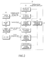
- FIG. 2 is a block diagram illustrating a camera setting parameter controller according to an embodiment of the present invention.
- the camera setting parameter controller 150 includes an ISO control determiner 151, an Auto Focus (AF) control determiner 152, an exposure control determiner 153, a zoom control determiner 154, a binning/subsampling control determiner 156, an edge enhance/noise reduction control determiner 157, and a camera setting parameter determiner 158.
- the camera setting parameter controller 150 receives at least one of a current camera setting parameter from the imaging controller 170, preview image data from the imaging unit 110, an image recognition result from the image recognition processor 120, and user input information from the input unit 160.
- the camera setting parameter controller 150 implements at least one of an ISO, an AF, an exposure, a zoom, a binning/subsampling, and an edge enhance/noise reduction.
- the camera setting parameter determiner 158 selects at least one of the camera setting parameters, and changes the selected camera setting parameter. For example, when the image recognition result by the image recognition processor 120 is dissatisfactory, i.e., when feature information included in the image recognition result does not meet a preset threshold condition (e.g., defined by the number, intensity, an amount, etc.) or the number of and an intensity of feature points does not meet a preset threshold value, the camera setting parameter determiner 158 selects at least one camera setting parameter to be changed based on a preset selection order of the camera setting parameters or the recognition result. Further, the camera setting parameter determiner 158 outputs the changed camera setting parameter to the imaging controller 170, which changes a setting of the imaging unit 110 according to the changed camera setting parameter.
- a preset threshold condition e.g., defined by the number, intensity, an amount, etc.
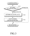
- FIG. 3 is a flowchart illustrating an ISO control process according to an embodiment of the present invention
- FIGs. 4A and 4B illustrate an object recognition result according to an ISO change according to an embodiment of the present invention.
- the ISO control process illustrated in FIG. 3 analyzes a capability recognizing an object within a preview image under a low luminance environment to increase a gain of the image sensor until the gain of the image sensor reaches a desired reference, which improves a capability of a recognition algorithm.
- the ISO control determiner 151 determines an object recognition capability in step S110, and when the recognition capability is unsatisfactory, determines an ISO control value in step S120, and controls imaging in step S130. When the recognition capability is satisfactory, the ISO control process is ended.
- the ISO control determiner 151 determines a capability of the recognition result received from the image recognition processor 120, i.e., whether the recognition result is satisfactory or dissatisfactory.
- the ISO control determiner 151 determines the capability of the recognition result based on feature information (e.g., the number of feature points, an edge intensity, and the number of matched feature points) identified through the recognition result.
- feature information e.g., the number of feature points, an edge intensity, and the number of matched feature points
- the "matched feature points” refer to feature points, among recognized feature points, corresponding to pre-stored feature points of reference image data
- the "edge intensity” refers to a contrast status of the edge, i.e., a brightness difference in a horizontal direction of the edge, a brightness difference in a vertical direction of the edge, or an average therebetween.
- the ISO control determiner 151 can directly receive information on whether the recognition capability is satisfactory from the image recognition processor 120.
- step S120 the ISO control determiner 151 determines the ISO control value (e.g., a gain of the image sensor) based on the recognition result.
- the ISO control value e.g., a gain of the image sensor
- FIG. 4A illustrates 54 feature points and 231 matched feature points, where the ISO value is 500
- FIG. 4B illustrates 62 feature points and 369 matched feature points, where the ISO value is 800.
- the number of feature points included in the reference image data stored in the memory 130 is 1151.
- the ISO control determiner 151 can determine the ISO value, which is one of the camera setting parameters, to be 800. That is, the ISO control determiner 151 compares at least one of the number of feature points, the edge intensity, and the number of matched feature points identified through the recognition result with a corresponding threshold value to calculate a desired ISO value.
- step S130 the ISO control determiner 151 transmits the determined ISO control value to the camera setting parameter determiner 158, which transmits the received ISO control value to the imaging controller 170.
- steps S110 to S130 may be repeated until the recognition result received from the image recognition processor 120 is satisfactory.
- an ISO control value at each repetitive step may be increased by a certain amount from the current ISO value.
- the ISO control process may be effectively applied, so that the camera setting parameter determiner 158 can perform the ISO control process when the total brightness of the preview image data is lower than a preset brightness.
- FIG. 5 is a flowchart illustrating an AF control process according to an embodiment of the present invention.
- the AF control process illustrated in FIG. 5 proposes a method of determining whether a focus is performed by using motion vector direction information of the object with conventional contrast information in operating an AF or a continuous AF for an image-based recognition service.
- the AF control determiner 152 determines an object recognition capability in step S210, and when the recognition capability is unsatisfactory, calculates a motion vector in step S220 and determines an object direction in step S230.
- the AF control determiner 152 controls imaging, i.e., performs AF, in step S240.
- the AF control process is terminated, when the recognition result is satisfactory in step S210 or when the object has moved in a top, bottom, left, or right direction on a focus plane of a previous image frame in step S230.
- the AF control determiner 152 determines a capability of the recognition result received from the image recognition processor 120, i.e., whether the recognition result is satisfactory or dissatisfactory. As described above, the AF control determiner 152 determines the capability of the recognition result based on feature information identified through the recognition result. Alternatively, the AF control determiner 152 can directly receive information on whether or not the recognition is satisfactory from the image recognition processor 120.
- step S220 the AF control determiner 152 compares a current image frame with a previous image frame, and determines how an object of the previous image frame has moved in the current image frame.
- a degree of the movement is represented by a motion vector. Because a method of estimating movement is already known, a detailed description of the method is omitted herein.
- the AF control determiner 152 determines whether the calculated movement direction of the object is a transverse direction or a longitudinal direction. That is, the AF control determiner 152 determines whether the object has moved in a top, bottom, left, or right direction on a focus plane of the previous image frame, or the object has moved in a front or back direction of the focus plane of the previous image frame. That is, when a size of the object of the current image frame is identical to a size of the object of the previous image frame, the object has moved in a transverse direction. When the size of the object of the current image frame is larger or smaller than the size of the object of the previous image frame, the object has moved in a longitudinal direction.
- step S240 the AF control determiner 152 determines to perform an AF and transmits a performance command to the camera setting parameter determiner 158.
- the camera setting parameter determiner 158 transmits the received performance command for the AF to the imaging controller 170.
- the transmission of the performance command of the AF may correspond to setting an on/off flag of the AF indicating activation/deactivation of an AF function to an on status.
- FIG. 5 illustrates that the AF control process is terminated after step S240, steps S210 to 240 may be repeated until the recognition result received from the image recognition processor 120 is satisfactory.
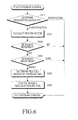
- FIG. 6 is a flowchart illustrating an exposure control process according to an embodiment of the present invention
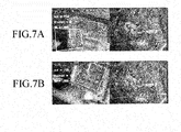
- FIG. 7 illustrates an object recognition result according to an exposure time change according to an embodiment of the present invention.
- the exposure control process illustrated in FIG. 6 reduces an exposure time to minimize blur by using motion vector information obtained from feature points of an object within a preview image, when a movement of the object is large.
- the image should still have a sufficient brightness.
- the exposure control determiner 153 determines an object recognition capability in step S310, and when the recognition capability is unsatisfactory, calculates a motion vector in step S320, and determines a movement in step S330.
- the exposure control determiner 153 determines a brightness in step S340.
- the exposure control determiner 153 determines a reduced amount of an exposure time in step S350, and controls imaging (reduces exposure time) in step S360.
- the exposure control process is terminated, when the recognition result is satisfactory in step S310, when no movement is determined in step S330, or when the exposure control determiner 153 determines that the brightness of the image frame is not larger than the threshold value in step S340.
- the exposure control determiner 153 determines a capability of the recognition result received from the image recognition processor 120, i.e., whether the recognition result is satisfactory or dissatisfactory. As described above, the exposure control determiner 153 determines the capability of the recognition result based on feature information identified through the recognition result or can directly receive information on whether or not the recognition is satisfactory from the image recognition processor 120.
- step S320 the exposure control determiner 153 compares a current image frame with a previous image frame, and determines whether an object of the previous image frame has moved in the current image frame.
- a degree of the movement is represented by a motion vector. Because a method of estimating movement is already known, a detailed description of the method is omitted herein.
- step S330 the exposure control determiner 153 determines whether the object has moved. That is, the exposure control determiner 153 compares a size of the calculated motion vector with a preset threshold value. When the size of the motion vector is larger than the threshold value, the exposure control determiner 153 determines that the object has moved. When the size of the motion vector is smaller than the threshold value, the exposure control determiner 153 determines that the object has not moved. Alternatively, the exposure control determiner 153 can compare (the size of the motion vector/a size of the preview image frame) with the preset threshold value.
- step S340 the exposure control determiner 153 compares a brightness of the current image frame with a preset threshold value. When the brightness of the image frame is larger than the threshold value, the exposure control determiner 153 determines that the brightness of the image frame is bright. When the brightness of the image frame is smaller than the threshold value, the exposure control determiner 513 determines that the brightness of the image frame is dark.
- step S350 the exposure control determiner 153 determines the reduced amount of the exposure time (i.e. frame rate (the number of frames per second)) based on whether an object has moved in the current image frame (or a size of the motion vector) and based on a brightness of the current image frame.
- frame rate the number of frames per second
- FIG. 7A illustrates 8 matched feature points, where a frame rate is 30 fps
- FIG. 7B illustrates 115 matched feature points, where the frame rate is 60 fps.
- the number of feature points included in the reference image data stored in the memory 130 is 1388.
- the exposure control determiner 153 may determine the frame rate, which is one of the camera setting parameters, to be 60 fps. Specifically, the exposure control determiner 153 compares at least one of the number of feature points, the edge intensity, and the number of matched feature points identified through the recognition result with a corresponding threshold value to calculate a desired frame rate.
- step S360 the exposure control determiner 153 transmits the determined frame rate to the camera setting parameter determiner 158, and the camera setting parameter determiner 158 transmits the received frame rate to the imaging controller 170.
- steps S310 to S320 may be repeated until the recognition result received from the image recognition processor 120 is satisfactory.
- a frame rate at each repetitive step may be increased by a certain amount from the current frame rate.
- FIG. 8 is a flowchart illustrating a zoom control process according to an embodiment of the present invention
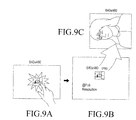
- FIGs. 9A to 9C illustrate an object recognition result according to a zoom change according to an embodiment of the present invention.
- a user selects an object displayed within a preview image frame having 604*480 resolution, e.g., a movie poster, as a Region Of Interest (ROI).
- ROI Region Of Interest
- the region of interest is automatically cropped from a raw image frame having full resolution larger than 640*480 resolution.
- the cropped region of interest is magnified and displayed (zoomed-in), and an object recognition for the magnified, displayed region of interest is performed.
- the zoom control process enables a recognition to be possible, even when an object visible in a preview image frame is small, because the zoom control process obtains a region of interest from a raw image frame having full resolution.
- step S410 the zoom control determiner 154 determines whether there is a user input related to the performance of the zoom control process through the input unit 160.
- step S420 the zoom control determiner 154 determines whether a crop status corresponds to "1". As illustrated in the table located in a left upper portion of FIG. 8 , the crop status is set to "0" in an initial status or in a zoom setting start status, set to "1” in a status during a zoom setting, and set to "2" in a zoom status or in a zoom cancel start status. The input status is set to "1” in a zoom setting start status or in a zoom cancel start status, and set to "0" in the remaining statuses.
- the crop status is set to "1" in step S430.
- step S440 the zoom control determiner 154 determines values of the crop status and the input status.
- Step S450 is performed when the crop status and the input status correspond to (0, 1)
- step S470 is performed when the crop status and the input status correspond to (1, 0)
- step S510 is performed when the crop status and the input status correspond to (2, 1).
- step S450 the zoom control determiner 154 sets the crop status and the input status to (1, 0), and in step S460, the zoom control determiner 154 calculates a coordinate and a size of the region of interest when the preview image frame is changed to a full image frame (i.e. a raw image frame).
- the coordinates of the region of interest may be obtained by a user input on a touch screen, and the size of the region of interest may be calculated by (full resolution/preview resolution*(ROI size + margin)).
- the zoom control determiner 154 then transmits the calculated coordinate and size of the region of interest to the imaging controller 170.
- step S470 the zoom control determiner 154 determines a capability of the recognition result received from the image recognition processor 120, i.e., whether the recognition result is satisfactory or dissatisfaetory. As described above, the zoom control determiner 154 determines the capability of the recognition result based on feature information identified through the recognition result.
- the zoom control determiner 154 sets the crop status to "2" in step S480. However, when the recognition result is not satisfactory, the zoom control determiner 154 stores the number of recognition dissatisfaction during the zoom control process in step S490. In step S500, the zoom control determiner 154 compares the number of accumulated recognition dissatisfactions with a preset threshold value.
- the zoom control determiner 154 sets the crop status and the input status to (0, 0) in step S510, and sets the imaging controller 170 such that the full image frame is returned to the preview image frame in step S520. Thereafter, the zoom control determiner 154 transmits the calculated coordinate and size of the region of interest to the imaging controller 170.
- FIG. 8 illustrates that the zoom control process is terminated when the number of accumulated dissatisfaction is smaller than or equal to the preset threshold value
- the zoom control process may return to step S410 until the recognition result received from the image recognition processor 120 is satisfactory or the number of accumulated recognition dissatisfaction is larger than the preset threshold value.
- determining the object recognition capability may be added before step S410, and the zoom control process may be automatically performed when the recognition result fails.
- the zoom control determiner 154 can perform instructions (indicating an instruction message for a region of interest selection and indicating a selection standby of plural regions of interest) related to the performance of the zoom control process.
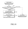
- FIG. 10 is a flowchart illustrating a binning/subsampling control process according to an embodiment of the present invention. Specifically, in FIG. 10 , when a full image is resized to a preview image, the binning/subsampling control process sets the setting values of binning and subsampling to be different from each other, which strengthens edge information and improves a recognition capability.
- the binning/subsampling control determiner 156 determines a capability of the recognition result received from the image recognition processor 120, i.e., whether the recognition result is satisfactory or dissatisfactory. As described above, the binning/subsampling control determiner 156 determines the capability of the recognition result based on feature information identified through the recognition result, or can directly receive information on whether or not the recognition is satisfactory from the image recognition processor 120.
- the binning/subsampling control process is terminated when the recognition result is satisfactory.
- the recognition result is dissatisfactory, i.e., feature information included in the image recognition result is not satisfied with preset threshold conditions
- the binning/subsampling control determiner 156 determines the binning/subsampling method in step S620.
- a process of the binning/subsampling control determiner 156 determines the binning/subsampling method includes the following sub-steps of:
- the binning/subsampling control determiner 156 can determine the binning and subsampling method based on the recognition result. Specifically, the binning/subsampling control determiner 156 may refer to a table, and select a binning and subsampling method corresponding to at least one of the number of feature points, an edge intensity, and the number of matched feature points grasped from the recognition result from the table.
- the table may be stored in the memory 130.
- step S630 the binning/subsampling control determiner 156 transmits the selected binning and subsampling method to the camera setting parameter determiner 158, and the camera setting parameter determiner 158 transmits the received binning and subsampling method to the imaging controller 170.
- FIG. 10 illustrates that the binning/subsampling control process is terminated after step S630, steps S610 to S630 may be repeated until the recognition result received from the image recognition processor 120 is satisfactory. In this case, a preset priority or random selection of different binning and subsampling methods at each of repetitive steps may be selected.
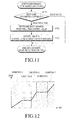
- FIG. 11 is a flowchart illustrating an edge enhance/noise reduction control process according to an embodiment of the present invention. Specifically, he edge enhance/noise reduction control process in FIG. 11 analyzes a capability recognizing an object within a preview image to increase an edge enhance/noise reduction control value until the edge enhance/noise reduction control value reaches a desired reference, which improves a capability of a recognition algorithm.
- the enhance/noise reduction control determiner 157 determines a capability of the recognition result received from the image recognition processor 120, i.e., whether the recognition result is satisfactory or dissatisfactory, in step S710. As described above, the enhance/noise reduction control determiner 157 determines the capability of the recognition result based on feature information identified through the recognition result, or can directly receive information on whether the recognition from the image recognition processor 120 is satisfactory.
- the edge enhance/noise reduction control process is terminated when the recognition result is satisfactory.
- the recognition result is dissatisfactory, i.e., feature information included in the image recognition result is not satisfied with preset threshold conditions
- the edge enhance/noise reduction control determiner 157 determines the edge enhance/noise reduction control value based on the recognition result in step S720.
- the edge enhance/noise reduction control determiner 157 may refer to a table, and select an edge enhance/noise reduction control value corresponding to at least one of the number of feature points, an edge intensity, and the number of matched feature points grasped from the recognition result from the table.
- FIG. 12 is a graph illustrating a table used in an edge enhance/noise reduction control process according to an embodiment of the present invention.
- At least one of the number of feature points, the edge intensity, and the number of matched feature points identified from the recognition result is classified by various conditions (conditions A to E), and there is a range of an edge enhance/noise reduction control value corresponding to the condition.
- step S730 the edge enhance/noise reduction control determiner 157 transmits the determined edge enhance/noise reduction control value to the camera setting parameter determiner 158, which transmits the received edge enhance/noise reduction control value to the imaging controller 170.
- FIG. 11 illustrates that the edge enhance/noise reduction control process is terminated after step S730, steps S710 to S730 may be repeated until the recognition result received from the image recognition processor 120 is satisfactory.
- an edge enhance/noise reduction control value at each of repetitive steps may be increased by a certain amount from the current edge enhance/noise reduction control value.
- the above-described embodiments of the present invention can be implemented by hardware and a combination of the hardware and software.
- the certain software can be stored, regardless of possibility of omission or rewrite, in volatile or non-volatile storage devices such as Read Only Memories (ROMs), memories such as Random Access Memories (RAMs), memory chips, devices or integrated circuits, and optically or magnetically recordable and machine-readable storage media such as a Compact Disc (CD), a Digital Versatile Disc (DVD), a magnetic disk, a magnetic tape, etc.
- ROMs Read Only Memories
- RAMs Random Access Memories
- a storage unit which can be included in the host device, can store a program including instructions for implementation of the embodiments of the present invention or the machine-readable storage media suitable for storing the programs.
Landscapes
- Engineering & Computer Science (AREA)
- Multimedia (AREA)
- Theoretical Computer Science (AREA)
- Physics & Mathematics (AREA)
- General Physics & Mathematics (AREA)
- Computer Vision & Pattern Recognition (AREA)
- Signal Processing (AREA)
- Artificial Intelligence (AREA)
- Health & Medical Sciences (AREA)
- Computing Systems (AREA)
- Databases & Information Systems (AREA)
- Evolutionary Computation (AREA)
- General Health & Medical Sciences (AREA)
- Medical Informatics (AREA)
- Software Systems (AREA)
- Studio Devices (AREA)
- Image Analysis (AREA)
- User Interface Of Digital Computer (AREA)
- Position Input By Displaying (AREA)
Applications Claiming Priority (1)
| Application Number | Priority Date | Filing Date | Title |
|---|---|---|---|
| KR1020110060396A KR101822655B1 (ko) | 2011-06-21 | 2011-06-21 | 카메라를 이용한 물체 인식 방법 및 이를 위한 카메라 시스템 |
Publications (2)
| Publication Number | Publication Date |
|---|---|
| EP2538660A2 true EP2538660A2 (de) | 2012-12-26 |
| EP2538660A3 EP2538660A3 (de) | 2016-10-12 |
Family
ID=46650337
Family Applications (1)
| Application Number | Title | Priority Date | Filing Date |
|---|---|---|---|
| EP12172735.8A Withdrawn EP2538660A3 (de) | 2011-06-21 | 2012-06-20 | Kameravorrichtung und -verfahren zur Erkennung eines Objektes unter Verwendung einer Kamera |
Country Status (4)
| Country | Link |
|---|---|
| US (1) | US9071749B2 (de) |
| EP (1) | EP2538660A3 (de) |
| KR (1) | KR101822655B1 (de) |
| CN (1) | CN102843513B (de) |
Cited By (4)
| Publication number | Priority date | Publication date | Assignee | Title |
|---|---|---|---|---|
| US10375312B2 (en) | 2014-06-03 | 2019-08-06 | Samsung Electronics Co., Ltd. | Imaging device and video generation method by imaging device |
| EP3907981A4 (de) * | 2019-02-28 | 2022-03-16 | Huawei Technologies Co., Ltd. | Verfahren zur steuerung der aufzeichnungsbildfrequenz und entsprechende vorrichtung |
| RU2782255C1 (ru) * | 2019-02-28 | 2022-10-25 | Хуавей Текнолоджиз Ко., Лтд. | Способ управления частотой кадров записи и соответствующее устройство |
| CN115410221A (zh) * | 2021-05-27 | 2022-11-29 | 株式会社日立制作所 | 对象物确定系统 |
Families Citing this family (33)
| Publication number | Priority date | Publication date | Assignee | Title |
|---|---|---|---|---|
| US8988578B2 (en) | 2012-02-03 | 2015-03-24 | Honeywell International Inc. | Mobile computing device with improved image preview functionality |
| JP2014222447A (ja) * | 2013-05-14 | 2014-11-27 | ソニー株式会社 | 画像処理装置および方法 |
| CN104881673B (zh) | 2014-02-28 | 2018-06-01 | 国际商业机器公司 | 基于信息整合的模式识别的方法和系统 |
| KR101689665B1 (ko) | 2014-07-04 | 2016-12-26 | 삼성전자 주식회사 | 이미지 센서, 이미지 센싱 방법, 그리고 이미지 센서를 포함하는 이미지 촬영 장치 |
| TWI542224B (zh) * | 2014-09-22 | 2016-07-11 | 瑞昱半導體股份有限公司 | 影像訊號處理方法以及影像訊號處理裝置 |
| US20160110791A1 (en) * | 2014-10-15 | 2016-04-21 | Toshiba Global Commerce Solutions Holdings Corporation | Method, computer program product, and system for providing a sensor-based environment |
| KR102126370B1 (ko) * | 2014-11-24 | 2020-07-09 | 한국전자통신연구원 | 동작 인식 장치 및 방법 |
| US10038836B2 (en) * | 2015-03-17 | 2018-07-31 | Mediatek Inc. | Automatic image capture during preview and image recommendation |
| WO2016197307A1 (en) * | 2015-06-08 | 2016-12-15 | SZ DJI Technology Co., Ltd. | Methods and apparatus for image processing |
| CN106454140B (zh) * | 2015-08-06 | 2019-06-25 | 联想(北京)有限公司 | 一种信息处理方法及电子设备 |
| KR20170046005A (ko) * | 2015-10-20 | 2017-04-28 | 삼성전자주식회사 | 얼굴 검출 방법 및 이를 지원하는 전자 장치 |
| JP6461372B2 (ja) * | 2015-11-25 | 2019-01-30 | 華為技術有限公司Huawei Technologies Co.,Ltd. | 撮影方法、撮影装置、及び端末 |
| CN105430287B (zh) * | 2015-12-30 | 2019-05-24 | Oppo广东移动通信有限公司 | 控制方法、控制装置及拍照系统 |
| CN105704394B (zh) * | 2016-02-25 | 2018-07-24 | 广东欧珀移动通信有限公司 | 取样方法、控制方法、取样装置、控制装置及电子装置 |
| KR101822169B1 (ko) * | 2016-03-11 | 2018-01-25 | 삼성전자주식회사 | 파노라마 영상을 제공하는 전자 장치 및 그 제어 방법 |
| US10560636B1 (en) | 2017-03-24 | 2020-02-11 | Cisco Technology, Inc. | Crop synchronized auto focus and exposure |
| CN108009998A (zh) * | 2017-11-27 | 2018-05-08 | 深圳大学 | 一种人物图像的构图裁剪方法、装置、设备及存储介质 |
| CN107959767B (zh) * | 2017-12-14 | 2020-04-10 | 中国科学院长春光学精密机械与物理研究所 | 一种以电视跟踪结果为导向的调焦调光方法 |
| US11500533B2 (en) | 2018-02-14 | 2022-11-15 | Lg Electronics Inc. | Mobile terminal for displaying a preview image to be captured by a camera and control method therefor |
| CN108334770B (zh) * | 2018-03-06 | 2019-01-29 | 石家庄裕兆科技有限公司 | 移动终端安全防护系统 |
| US11070729B2 (en) * | 2018-07-27 | 2021-07-20 | Canon Kabushiki Kaisha | Image processing apparatus capable of detecting moving objects, control method thereof, and image capture apparatus |
| US10863097B2 (en) * | 2018-08-21 | 2020-12-08 | Gopro, Inc. | Field of view adjustment |
| US11082620B2 (en) * | 2018-09-26 | 2021-08-03 | Qualcomm Incorporated | Zoomed in region of interest |
| CN111385484B (zh) * | 2018-12-28 | 2021-06-25 | 北京字节跳动网络技术有限公司 | 信息处理方法和装置 |
| CN109654997B (zh) * | 2019-02-01 | 2020-10-30 | 河南科技大学 | 一种基于机器视觉的穴盘孔精准定位装置及方法 |
| CN111726541A (zh) * | 2019-03-21 | 2020-09-29 | 北京猎户星空科技有限公司 | 一种拍摄参数的确定方法、装置、设备及介质 |
| KR102228047B1 (ko) * | 2020-06-30 | 2021-03-16 | (주)포미트 | 지하 매설물 관리를 위한 증강현실 기반의 위치 정합 표시 장치 및 방법 |
| KR20220159131A (ko) | 2021-05-25 | 2022-12-02 | 삼성전자주식회사 | 이미지 센서 및 동적 비전 센서를 포함하는 전자 장치 및 그 동작 방법 |
| US12347143B2 (en) * | 2021-06-03 | 2025-07-01 | Nec Corporation | Reinforcement-learning based system for camera parameter tuning to improve analytics |
| US12254620B2 (en) | 2021-08-27 | 2025-03-18 | 3M Innovative Properties Company | Replacement part validation systems and methods |
| JP2024179189A (ja) * | 2023-06-14 | 2024-12-26 | キヤノン株式会社 | 撮像装置、制御方法、並びにプログラム |
| WO2025154936A1 (ko) * | 2024-01-15 | 2025-07-24 | 삼성전자 주식회사 | 이미지를 처리하는 방법 및 그 전자 장치 |
| WO2026010082A1 (ko) * | 2024-07-02 | 2026-01-08 | 삼성전자 주식회사 | 카메라의 셔터 지연을 줄이는 전자 장치, 방법 및 저장 매체 |
Family Cites Families (19)
| Publication number | Priority date | Publication date | Assignee | Title |
|---|---|---|---|---|
| US7526100B1 (en) * | 2003-04-22 | 2009-04-28 | Advanced Optical Systems, Inc. | System for processing and recognizing objects in images |
| CN100345154C (zh) * | 2005-06-29 | 2007-10-24 | 上海大学 | 足球机器人视觉快速识别方法 |
| JP2007251258A (ja) | 2006-03-13 | 2007-09-27 | Fujitsu Ten Ltd | 画像認識装置 |
| GB2452512B (en) | 2007-09-05 | 2012-02-29 | Sony Corp | Apparatus and method of object tracking |
| JP5083090B2 (ja) | 2007-09-18 | 2012-11-28 | ソニー株式会社 | 表示制御装置、撮像装置、表示制御方法およびプログラム |
| KR20090067230A (ko) | 2007-12-21 | 2009-06-25 | 손승남 | 차량번호인식을 위한 카메라 제어방법 |
| JP5202037B2 (ja) * | 2008-02-29 | 2013-06-05 | キヤノン株式会社 | 特徴点位置決定方法及び装置 |
| KR100926978B1 (ko) * | 2008-04-08 | 2009-11-17 | 삼성전자주식회사 | 영상 수집 제어 방법 및 장치 |
| US8249331B2 (en) * | 2008-04-09 | 2012-08-21 | Applied Materials Israel, Ltd. | Method and system for evaluating an object |
| KR101446779B1 (ko) * | 2008-07-09 | 2014-10-01 | 삼성전자주식회사 | 플래시 사용을 제한하는 촬영 제어 방법 및 장치 |
| JP2010103949A (ja) * | 2008-10-27 | 2010-05-06 | Fujifilm Corp | 撮影装置、方法およびプログラム |
| KR101082878B1 (ko) | 2009-01-29 | 2011-11-11 | 연세대학교 산학협력단 | 홍채 영상 복원 방법 |
| JP5249077B2 (ja) * | 2009-02-17 | 2013-07-31 | キヤノン株式会社 | 撮像装置及び画像処理方法 |
| WO2010095352A1 (ja) * | 2009-02-18 | 2010-08-26 | パナソニック株式会社 | 撮像装置 |
| KR101039423B1 (ko) | 2009-05-22 | 2011-06-07 | 한국인식산업(주) | 얼굴밝기 측정에 의한 카메라의 노출과 셔터스피드 제어방법 및 그 제어방법에 의한 카메라 장치 |
| CN101790048B (zh) * | 2010-02-10 | 2013-03-20 | 深圳先进技术研究院 | 智能摄像系统及方法 |
| JP2011223296A (ja) * | 2010-04-09 | 2011-11-04 | Sony Corp | 撮像制御装置および撮像制御方法 |
| KR101606727B1 (ko) * | 2010-06-25 | 2016-03-28 | 엘지전자 주식회사 | 휴대 단말기 및 그 동작 방법 |
| US8665355B2 (en) | 2010-11-22 | 2014-03-04 | Canon Kabushiki Kaisha | Image capture with region-based adjustment of contrast |
-
2011
- 2011-06-21 KR KR1020110060396A patent/KR101822655B1/ko active Active
-
2012
- 2012-06-20 EP EP12172735.8A patent/EP2538660A3/de not_active Withdrawn
- 2012-06-21 US US13/529,688 patent/US9071749B2/en active Active
- 2012-06-21 CN CN201210212422.6A patent/CN102843513B/zh not_active Expired - Fee Related
Non-Patent Citations (1)
| Title |
|---|
| C. TSAI: "Effects of 2-D Preprocessing on Feature Extraction: Accentuating Features by Decimation, Contrast Enhancement, Filtering", EE262: 2D IMAGING PROJECT REPORT, STANFORD UNIVERSITY, 1 January 2008 (2008-01-01), pages 1 - 9, XP055270742, Retrieved from the Internet <URL:https://pdfs.semanticscholar.org/185e/62d607becc8d0ee2409a224a36c58b084ab3.pdf> [retrieved on 20160504] * |
Cited By (6)
| Publication number | Priority date | Publication date | Assignee | Title |
|---|---|---|---|---|
| US10375312B2 (en) | 2014-06-03 | 2019-08-06 | Samsung Electronics Co., Ltd. | Imaging device and video generation method by imaging device |
| EP3907981A4 (de) * | 2019-02-28 | 2022-03-16 | Huawei Technologies Co., Ltd. | Verfahren zur steuerung der aufzeichnungsbildfrequenz und entsprechende vorrichtung |
| RU2782255C1 (ru) * | 2019-02-28 | 2022-10-25 | Хуавей Текнолоджиз Ко., Лтд. | Способ управления частотой кадров записи и соответствующее устройство |
| AU2020229917B2 (en) * | 2019-02-28 | 2023-05-18 | Huawei Technologies Co., Ltd. | Recording frame rate control method and related apparatus |
| US11818497B2 (en) | 2019-02-28 | 2023-11-14 | Huawei Technologies Co., Ltd. | Recording frame rate control method and related apparatus |
| CN115410221A (zh) * | 2021-05-27 | 2022-11-29 | 株式会社日立制作所 | 对象物确定系统 |
Also Published As
| Publication number | Publication date |
|---|---|
| US9071749B2 (en) | 2015-06-30 |
| EP2538660A3 (de) | 2016-10-12 |
| KR101822655B1 (ko) | 2018-01-29 |
| KR20120140571A (ko) | 2012-12-31 |
| US20120327269A1 (en) | 2012-12-27 |
| CN102843513A (zh) | 2012-12-26 |
| CN102843513B (zh) | 2017-09-22 |
Similar Documents
| Publication | Publication Date | Title |
|---|---|---|
| US9071749B2 (en) | Camera apparatus and method of recognizing an object by using a camera | |
| US8988529B2 (en) | Target tracking apparatus, image tracking apparatus, methods of controlling operation of same, and digital camera | |
| JP5088118B2 (ja) | 焦点調節装置 | |
| JP4727117B2 (ja) | 知的特徴選択およびパンズーム制御 | |
| US20100157107A1 (en) | Image Apparatus And Electronic Apparatus | |
| US8629915B2 (en) | Digital photographing apparatus, method of controlling the same, and computer readable storage medium | |
| JP5592006B2 (ja) | 三次元画像処理 | |
| US9160922B2 (en) | Subject detection device and control method for the same, imaging apparatus, and storage medium | |
| EP2768214A2 (de) | Verfahren zur Verfolgung eines Objekts mit einer Kamera und Kamerasystem zur Objektverfolgung | |
| JP5210843B2 (ja) | 撮像装置 | |
| JP2014077994A (ja) | 画像表示装置、その制御方法および制御プログラム並びに撮像装置 | |
| US9489721B2 (en) | Image processing apparatus, image processing method, and storage medium | |
| JP4487872B2 (ja) | 画像処理装置および方法、プログラム並びに記録媒体 | |
| JP4894708B2 (ja) | 撮像装置 | |
| JP5949559B2 (ja) | 画像処理装置、撮像装置および画像処理プログラム | |
| WO2018196854A1 (zh) | 一种拍照方法、拍照装置及移动终端 | |
| US8643730B2 (en) | Imaging device and image capturing method | |
| US10070039B2 (en) | Image processing device and image processing method | |
| JP6671323B2 (ja) | 撮像装置 | |
| US20210029291A1 (en) | Apparatus, method, and storage medium | |
| JP6673333B2 (ja) | 画像処理装置と画像処理方法および撮像装置 | |
| JP2012074894A (ja) | 電子カメラ | |
| JP6044123B2 (ja) | 被写体追尾装置および電子カメラ並びに被写体追尾プログラム | |
| JP2012235305A (ja) | 画像処理装置及びその制御方法 | |
| JP4936799B2 (ja) | 電子カメラ |
Legal Events
| Date | Code | Title | Description |
|---|---|---|---|
| PUAI | Public reference made under article 153(3) epc to a published international application that has entered the european phase |
Free format text: ORIGINAL CODE: 0009012 |
|
| AK | Designated contracting states |
Kind code of ref document: A2 Designated state(s): AL AT BE BG CH CY CZ DE DK EE ES FI FR GB GR HR HU IE IS IT LI LT LU LV MC MK MT NL NO PL PT RO RS SE SI SK SM TR |
|
| AX | Request for extension of the european patent |
Extension state: BA ME |
|
| PUAL | Search report despatched |
Free format text: ORIGINAL CODE: 0009013 |
|
| AK | Designated contracting states |
Kind code of ref document: A3 Designated state(s): AL AT BE BG CH CY CZ DE DK EE ES FI FR GB GR HR HU IE IS IT LI LT LU LV MC MK MT NL NO PL PT RO RS SE SI SK SM TR |
|
| AX | Request for extension of the european patent |
Extension state: BA ME |
|
| RIC1 | Information provided on ipc code assigned before grant |
Ipc: H04N 5/232 20060101AFI20160905BHEP |
|
| STAA | Information on the status of an ep patent application or granted ep patent |
Free format text: STATUS: REQUEST FOR EXAMINATION WAS MADE |
|
| 17P | Request for examination filed |
Effective date: 20170111 |
|
| RBV | Designated contracting states (corrected) |
Designated state(s): AL AT BE BG CH CY CZ DE DK EE ES FI FR GB GR HR HU IE IS IT LI LT LU LV MC MK MT NL NO PL PT RO RS SE SI SK SM TR |
|
| STAA | Information on the status of an ep patent application or granted ep patent |
Free format text: STATUS: EXAMINATION IS IN PROGRESS |
|
| 17Q | First examination report despatched |
Effective date: 20180124 |
|
| STAA | Information on the status of an ep patent application or granted ep patent |
Free format text: STATUS: THE APPLICATION IS DEEMED TO BE WITHDRAWN |
|
| 18D | Application deemed to be withdrawn |
Effective date: 20230103 |