EP2539088B1 - Tête de rinçage - Google Patents
Tête de rinçage Download PDFInfo
- Publication number
- EP2539088B1 EP2539088B1 EP11709632.1A EP11709632A EP2539088B1 EP 2539088 B1 EP2539088 B1 EP 2539088B1 EP 11709632 A EP11709632 A EP 11709632A EP 2539088 B1 EP2539088 B1 EP 2539088B1
- Authority
- EP
- European Patent Office
- Prior art keywords
- flushing
- hose
- flushing head
- head
- nozzles
- Prior art date
- Legal status (The legal status is an assumption and is not a legal conclusion. Google has not performed a legal analysis and makes no representation as to the accuracy of the status listed.)
- Active
Links
Images




Classifications
-
- B—PERFORMING OPERATIONS; TRANSPORTING
- B08—CLEANING
- B08B—CLEANING IN GENERAL; PREVENTION OF FOULING IN GENERAL
- B08B9/00—Cleaning hollow articles by methods or apparatus specially adapted thereto
- B08B9/02—Cleaning pipes or tubes or systems of pipes or tubes
- B08B9/027—Cleaning the internal surfaces; Removal of blockages
- B08B9/04—Cleaning the internal surfaces; Removal of blockages using cleaning devices introduced into and moved along the pipes
- B08B9/049—Cleaning the internal surfaces; Removal of blockages using cleaning devices introduced into and moved along the pipes having self-contained propelling means for moving the cleaning devices along the pipes, i.e. self-propelled
- B08B9/0495—Nozzles propelled by fluid jets
-
- E—FIXED CONSTRUCTIONS
- E03—WATER SUPPLY; SEWERAGE
- E03F—SEWERS; CESSPOOLS
- E03F9/00—Arrangements or fixed installations methods or devices for cleaning or clearing sewer pipes, e.g. by flushing
Definitions
- the present invention relates to a flushing head for a flushing hose to be used in a duct inspection, having a plurality of nozzles distributed along a circumference about a longitudinal axis, which are connected via at least one feed to a flushing head access provided for the arrangement of a flushing hose. Furthermore, the invention relates to a flushing device with a flushing hose provided with a previously described flushing head, in particular a flushing carriage for cleaning the channel.
- a device which comprises a flushing head according to the preamble of claim 1.
- This flushing head is guided along with the connected flushing hose via a carrier vehicle provided with a camera along the main channel to the house connection channel and introduced from there via a pivoting arm in the house connection channel.
- the carrier vehicle is in this case controlled by an associated camera carriage, while the flushing hose with the flushing head is operated by a flushing vehicle.
- a flushing head which has an asymmetrical arrangement of the nozzles, whereby the front part of the nozzle head along the pipe wall along schieift and is automatically pressed into this upon reaching a A concernedelgkanalausündung. Whether this nozzle can float is not revealed.
- a nozzle which can be spirally guided along a pipe wall, this rotation being effected by a rotation of the hose.
- the JP 11114513 A discloses a rinsing nozzle provided with an additional camera head, the nozzle body of which can rotate.
- DE 196 01 253 A1 is to remove a lying in a channel to be cleaned on the floor rinsing nozzle, which also has a camera.
- the DE 42 26 336 describes a cleaning device for channels or pipes with a rotary tilting joint to a flushing hose rotatably and tiltably connected nozzle body arranged at the back and directed backwards nozzles for bottom-side advancement.
- the nozzle for generating a counter to the weight of the flushing head directed and this exceeding force are distributed asymmetrically about the longitudinal axis.
- the number, size and / or power of the nozzles is distributed asymmetrically. The distribution is such that the thrust exerted by the in-use nozzles is directed against the weight of a normally-located nozzle and results in lifting of the flushing head.
- the flushing head and optionally the associated hose can be guided alone and lifted through the channel and is independent of a carrier vehicle, over whose arm it is guided in the direction of a channel to be cleaned.
- the flushing head can be controlled and / or guided, in particular in a direction transverse to its longitudinal direction.
- the flushing head of the laterally and / or obliquely rearwardly directed nozzles with respect to the longitudinal axis of the flushing head the latter not only receives a preferred direction in the direction of the longitudinal axis of the channel to be cleaned, but also transversely thereto.
- the flushing head can also be deliberately directed into channels extending transversely from a channel, counter to its longitudinal direction.
- the nozzles are controllable for this purpose, ie closed and / or controllable, for example, via magnetic or other eg pressure-controllable valves.
- the flushing head By virtue of the force exerted by the force of the flushing head, which is exerted on the flushing head by the medium during operation, the flushing head can be raised and, in particular, can be lifted over the multiplicity of contaminants on the bottom of a channel, such as paper or fecal residues. It can also be more easily introduced into house connection channels.
- the flushing head is associated with a joint through which the flushing hose can be attached to the flushing head in an articulated manner.
- This joint can be arranged in a region of the hose directed toward the flushing head, wherein the hose is in turn connected to a flushing head described above.
- the rinsing head access is formed by the joint so that the joint is part of the rinsing head and has a preferably flange-shaped region on which the rinsing hose can be fastened.
- a joint has particular advantages in combination with a rinsing head which has nozzles for generating a counter to the weight of the rinsing head directed and exceeding this force, the nozzles are distributed in particular according to their size and / or number asymmetrically about the longitudinal axis.
- the influence of the hose weight during operation on the flushing head can be reduced, in particular in such a way that the hose can be introduced at an angle at an angle to the flushing head.
- the flushing head can be better aligned at the end of the hose in a desired position.
- the force acting on the flushing head weight of the hose and the water guided in this are not completely excluded, but by the joint, the influence of the force exerted by the hose and the water flowing in this flowing force is minimized to the orientation of the flushing head.
- the flushing head can thus be better supported in the channel, in particular at its apex or on the walls and is better controllable.
- At least one downwardly operating nozzle is provided with a larger free inner diameter than an upwardly directed nozzle. That is to say, the impulse which can be exerted on the flushing head by this nozzle against the weight force is greater than the impulse acting in the direction of the weight force, so that in total there is a force against the weight force.
- This allows the nozzle to lift well.
- Particularly advantageous is the use of at least two downwardly acting nozzles, which leads to a stabilization of the nozzle. The nozzle then staggers less in the raised state. It is understood that under downwardly acting nozzle quite well understood an obliquely downward / rearward acting nozzle.
- the flushing head in addition in the direction of the longitudinal axis of the channel pushed, easily in junctions that point up, retract.
- the flushing head is rotatable so that it can move laterally from the apex of a channel and thereby pushed past a branch or pulled by the water jet.
- the rotation of a flushing head takes place here via a tube arranged on the flushing head, that is to say it can be effected manually. This is also possible over distances of several tens of meters.
- the nozzle can also be designed to be controllable in order to be able to specifically move into such a channel.
- a stabilization of the floating flushing head during operation is also achieved in that the flushing head has both predominantly for levitating the flushing head used nozzles and other propulsion nozzles, these nozzles differ in that the beam directions of levitation and propulsion nozzles occupy different angles with the longitudinal axis.
- the flushing head preferably has a flushing capacity of 200-400 l / min, more preferably 250 to 350 l / min, even more preferably 300-350 l / min. This provides a good balance between the amount required for levitation of the flushing head and the maximum amount that can be introduced into a domestic connection duct.
- a flushing head in which this has at least one and in particular upper-side guide surface, which is provided to support the guidance of the flushing head at the apex or a wall of a channel.
- This may be, for example, an extended contact surface, that is, the part of the flushing head having the guide is designed in such a way that the flushing head can lean against the duct wall approximately parallel or slightly obliquely therefrom.
- the guide surface is preferably a plane or slightly rounded surface, which stands out from the further outer contour of the flushing head and, for example, characterized by flattening of the flushing head on one side.
- the guide surface serves as a system, via which a floating flushing head can be supported on a channel wall and thereby leads to an alignment of the flushing head in the channel.
- the guide surface here is a part of a guide body that is angled relative to a part of the flushing head that has the nozzles or that is offset with respect to its longitudinal axis for better alignment of the flushing head to be pushed through a channel.
- the nozzle part which then also has the receptacle for the flushing hose, is slightly angled with respect to its longitudinal axis relative to the channel wall, which also leads to a stable guidance of the flushing head through a channel in combination with a then obliquely away from the flushing head hose.
- the longitudinal axis of the hose and the nozzle part may also correspond approximately.
- the flushing head comprises a functional part, which has, for example, a receiving space.
- the functional part in particular the functional part formed integrally with the guide body, can be made lighter than the nozzle part, which again benefits a guidance of the flushing head.
- the functional part may also be integrally or in particular interchangeably connected to the nozzle part and connect directly or indirectly thereto.
- the flushing head is provided with an opening in the main movement direction receiving space within the functional part, in which a camera is arranged.
- the flushing head and in particular in the operating position with a flushing hose arranged thereon are able to completely replace the camera or support carriage known in the prior art.
- the rinsing head and rinsing hose can be routed without carrier device in main channels as well as in house connection channels and due to the integrated camera, camera carts are no longer necessary. This leads to significantly more favorable channel inspection expectations, whereby the camera can be operated with the rinse car, for example, via a data recording and playback device such as a small portable computer.
- the camera may preferably also be a pivotable camera which is arranged on the outside at least partially in the receiving space or on the rinsing head and leads to a better image of the channel.
- a camera can also be used to inspect subfloors directly below the flushing head.
- a guide surface which also by guide flanges such as webs or other guide elements can be supplemented or replaced, and the associated targeted alignment of the flushing head in the camera specifically aligned.
- angled bottom of the rinse By an opposite to a guide surface or a guide element in longitudinal section angled bottom of the rinse can be particularly well inserted into house connection channels. If a house connection channel is to be examined, the flushing head is pushed / pulled in its direction and possibly rotated about its longitudinal axis. Due to the lack of resistance on the guide surface, the flushing head rotates in the e.g. left or right branching channel inside, which is supported by the bevelled lower side and the associated pointed execution of the flushing head.
- the front-facing lens of the camera is surrounded by an LED light ring, which illuminates the space to be considered well.
- the device is further improved if the rinsing head is provided with a locating device, via which a clear localization in addition to any known bekanten measures such as meter wheels is possible.
- the joint is provided with a hollow ball head part, which is arranged in a part of the flushing head and in particular is movably mounted in corresponding joint cup areas of the flushing head.
- the water can then be transported through the hollow ball head part in the direction of the nozzles and the hose can be flange-mounted centrally on the hollow flange part.
- the joint according to the invention has a degree of freedom and thus a pivot axis through which the flushing head relative to the hose An anglebar is.
- this pivot axis is transverse to the direction of the force provided for lifting the nozzle.
- the flushing head may be provided with a light aiming device, which is preferably equipped with a laser or other blasting medium for illuminating a small punctiform area.
- a light aiming device which is preferably equipped with a laser or other blasting medium for illuminating a small punctiform area.
- a flushing head according to the invention can be provided with a position sensor, via which an orientation of the flushing head is defined in one or more dimensions can be. This also improves the positioning of objects in the channel.
- the pivot axis In a working position in which the flushing head is located at the upper vertex of a channel, the pivot axis extends in a rectilinear channel preferably at least approximately in a plane which is parallel to the longitudinal direction of the channel and in which the pivot axis is employed at right angles.
- a pivot axis thus serves to transmit a torque from the hose via the joint to the flushing head and to align the flushing head.
- the combination of a rotary motion associated with an additional kinking of the flushing head this can be ushered into branches of the channel in a much simpler way and can easily reflect kinks and changes in direction of the channel with.
- the part of the flushing head which does not have the joint part facing the flushing hose can thus be converted, for example, by a rotation of the hose through 90 ° in a clockwise direction into a position lying on a right side wall of the channel.
- the flushing head By the unbalanced nozzles or by the water discharged through the nozzles exerted Force the flushing head is then pressed in the presence of a branch arranged on this right side in this, wherein the joint kinks.
- the introduction of the flushing head into such a branch can be improved by a flattening of the flushing head on a bottom surface opposite the guide surface.
- the flushing head is thus preferably flattened on its underside and formed angled to its longitudinal extent.
- the one degree of freedom having joint is provided with a flange which advantageously has a profiling for connection to the flushing hose.
- a flushing device for example a flushing trolley for channel cleaning, is able, in particular in a training with a camera, to replace the camera carriage previously known from the prior art. Even without an integrated camera can be dispensed with a guidance of the hose through the camera dolly.
- the flushing hose can be easily pushed past the rake car operator behind a camera dolly or pushed or pulled from another side of the duct to the camera dolly. The often erroneous pivoting of the flushing hose by the vulnerable mechanics of the carrier vehicle is eliminated.
- the flushing device comprises a flushing hose rotating device, by means of which the flushing hose is rotatable about its longitudinal axis. While experienced personnel can also turn the flushing hose directly manually, this can Rotation, which may require a greater force application with correspondingly far-developed irrigation tubes, be supported by, for example, to be arranged on the purge hose lever. This may also be a device provided with motor or hydraulic actuating means.
- the flushing device of a further embodiment of the invention is provided with a telescopic arm, which allows the easier handling of the flushing arm and in particular in a direction vertical to the horizontally extending ground or ground is movable.
- the flushing hose rotation device preferably has a holding unit with a recess provided for receiving the hose, in which the flushing hose can be held against rotation.
- the holding unit can advantageously be arranged at one end of the telescopic arm and be rotatable about a longitudinal direction of the flushing hose or about an axis which runs parallel to the longitudinal extent of the telescopic arm.
- the rinsing tube rotating device preferably has at least one pressing means which can be transferred from a non-operating position into a pressing position, by means of which a force can be exerted transversely and / or longitudinally of the tube by the rotating device.
- a torque can be transmitted to the hose, which extends through the hose to the. Flushing continues and at least partially contributes to the rotation of the flushing head.
- the flushing hose rotating device is in particular motor, pneumatic and / or electrically operable, so that for a rotation of the hose from the operating personnel of the hose does not have to be moved by hand.
- the rotation is electrically actuated.
- the pressure means is in particular pneumatically actuated, since then a maximum pressure on the hose is adjustable via simple pressure limiter. Rather, the operator may focus on the rinse head and its data displayed by a pickup device.
- the control of the flushing hose can in this case be effected in particular via a joystick control or a rotary wheel control, which permit an intuitive guidance of the flushing head.
- pressure means or in particular rotating or rotatable pressure means in the form of wheels, belts, chains or the like. Rolled on the hose means are used.
- the or the pressure means have a profiling which acts in the pressure position transversely to the longitudinal direction of the flushing hose, so that a rotation of the flushing hose can be improved without slippage of the hose.
- these are rollers, belts or the like.
- the pressure means is designed as a rotating and / or rotatable attachment means, so that a pivoting of the hose and thus the flushing head and a propulsion thereof can be carried out independently and simultaneously.
- the investment means may also be designed to drive the rinsing head.
- the control of the Spülschlauchmativor substances which in particular is pneumatically actuated, is aligned with the data collection to the effect that the operation of the device and the resulting movement of the flushing head are detected directly and preferably position data on location and orientation of the flushing head can be displayed directly.
- the main extension direction of the telescopic arm and the pressing direction of the pressure means are aligned transversely to each other in order to allow optimum control of the flushing head.
- this can also serve to cover a channel opening at the same time, so that the protection of the operating personnel also secured by the Spipposchlauchpatvorraum.
- the flushing hose can advantageously at least partially with the Camera cables are connected, for example via a shrink tube.
- the supply line can also be integrated into the flushing hose itself, for example, in the armor or its water-bearing cavity, which then leads to a better handling thereof by only one cable.
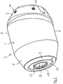
- An inventive flushing head has a nozzle part 2, to which a functional part 4 is flanged sealingly.
- a functional part 4 is flanged sealingly.
- an upper edge 6 in the longitudinal direction of the flushing head is longer than a lower edge 7. This results in a bevelled end flare to the nozzle part 2, whereby the area around the edge 6 is suitable as a guide surface.
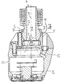
- a receiving space 8 (see. Fig. 2 ) is sealed with a cover 9.
- a camera included with an LED light ring is set in the receiving space 8.
- the cover 9 has a transparent annular disk 11 which is to be screened by the LED and which delimits in this case a circular disk 19 and a lens 12 of the camera.
- the lens of the camera can be focused.
- the nozzle part 2 has a plurality of nozzles 14 which are arranged in the circumferential direction about a longitudinal axis of the nozzle part 2 and about a longitudinal axis of the guide body or functional part 4.
- the nozzle part 2 further has a rinsing head access 16, which serves to define a rinsing hose. From the Spülkopfzugang 16 from the nozzles with the medium, preferably water, supplied.
- the flushing head During operation of the flushing head, it is designed with a flushing hose arranged thereon by virtue of the nozzles in such a way that it rests with the surface around the edge 6 without twisting of the flushing head in the orientation shown on an upper wall or a vertex of a channel to be inspected or cleaned ,
- the camera 17 looks in this case in the direction of a longitudinal direction of the channel.
- the angled arrangement of the nozzle part 2 and guide body 4 leads to a stable position, although the weight of the hose pulls the flushing head downwards, but this is due to the oblique arrangement of the nozzle part 2 is already partially compensated. If the functional space 8 with the camera 17 is not flanged at an angle to the nozzle part or is not formed obliquely, the camera 17 could alternatively be arranged obliquely in the receiving space to look in the longitudinal direction of the channel.
- the cover 11 shown of the LED unit 18 and the glass cap 19 of the camera could be designed so that they provide a "fish-eye" view of the environment and thus provide the greatest possible coverage of the space to be considered.
- a positioning pin 21 serves for the exact arrangement of the camera unit in the functional space.
- a seal 25 pinching brass ring 22 a seal of the intended for receiving the camera cable channel 23 is achieved. This is then sealed with the camera cable opposite the channel to be cleaned.
- Nozzle part 2 and guide body 4 are fastened to each other via screw means 24, which causes easy maintenance, in particular of the nozzle part 2.
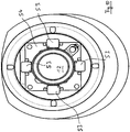
- FIG. 3 In the rear view of the nozzle part according to the arrow A from Fig. 2 is in Fig. 3 the arrangement of the nozzles about a longitudinal axis 26 of the nozzle part 2 can be seen.
- Lower nozzles 27 are formed larger than the nozzles 14 and serve in particular as floating nozzles.
- the in the figure in the outer circumference also present on the right side nozzles 14 are used with the two in the Fig. 1 visible nozzles 14 primarily as cleaning nozzles.
- these nozzles and the other also used as a propulsion nozzles nozzles 28 has a stabilizing function of in the channel during operation floating flushing head. It is understood that the nozzles 27 and 28 also have cleaning or counter to the force of gravity effects.
- the jet direction of the inner nozzles 28 and the outer nozzles 14 and 27 are at an angle to each other and with respect to the longitudinal axis 26 at different angles ( Fig. 4 ).
- the guide body is also angled with its longitudinal axis 29 by about 13 ° relative to the axis 26. Especially at values between 8 ° and 20 °, a good guidance of the rinsing heads in the channel has resulted.
- the cone-shaped head of the guide body ensures even with heavy soiling and obstacles on the channel inner circumference for a good way to slide over them.
- the lateral surface of the cone 5 is inclined relative to the lateral surface 31 of the guide body to advantageously 20 ° to 45 ° in order to slide along obstacles well. Due to the structure of the flushing head results in a preferred direction of movement of the flushing head forward / upward, but which leads to a rotation of the flushing head to a pivoting of the flushing head to one side of the channel. In addition, this orientation of the flushing head is particularly well suited to meet at a shallow angle to a main channel abutting house water connections and to introduce the flushing head can in this. For this purpose, in particular provided with controllable nozzles rinsing heads along a longitudinal axis For example, be rotated by 90 ° or 180 ° and be provided with an opposite thrust to push well into the small house connection channels can.
- the camera is shown as a simple built-in part, which is completely inserted into the receiving space 8.
- the cover 9 is also a single mounting part, in which the individual lenses or to be screened cover are used. The whole device can thus be both easy to build and disassemble for maintenance purposes.
- the nozzles are formed as by means of Allen key in the nozzle part 2 can be screwed, preferably made of ceramic nozzles.
- the flushing head with guide body 4 and nozzle part 2 is formed in two parts, it can of course be formed in one piece or in several parts.
- a functional part 4 can be replaced as needed.
- the embodiment of the invention according to Fig. 5 a functional part 4, which has a non-cylindrical base body. Rather, the functional part 4 is designed so that it has a clearly pronounced guide surface 32 which serves to guide or align the flushing head.
- the functional part 4 is further offset with respect to a vertical axis at the nozzle part 2, which is particularly in the Fig. 6 can be seen and leads to an offset of the two longitudinal axes of the nozzle part and functional part 4.
- a longitudinal axis 33 of the functional part is offset relative to a longitudinal axis 26 upwards.
- the flushing head according to Figure 6 an opposite to the previous embodiment modified LED ring around the lens.
- the receiving space is provided with a peripheral edge 34, which lead to a precise arrangement of the camera 17 in the receiving space 8.
- guide elements in the form of, for example, longitudinally arranged webs may be provided on the flushing head, which serve for the targeted alignment of the flushing head or support its movement through the channel.
- the flushing head according to the embodiment of the Fig. 7 is like the rinse head after Fig. 1 constructed in several parts and has a nozzle part 2, in the present invention, a universal joint is integrated as a joint 40.
- a flange portion 41 of the hinge 40 protrudes from the flushing head and serves to attach a clamp 42 of the flushing hose end.
- Part 42 represents a shortened press-on coupling, which is flanged to the flange 41 of the joint head and preferably a maximum Extension of 6 cm considered in the direction of the flushing hose has.
- the flushing head can be improved into a branch, which is arranged, for example, at a 90 ° angle to the channel.
- flushing heads according to the invention are already adequately guided if they have two points which are spaced behind one another in the longitudinal direction and serve the abutment at a vertex of the channel.
- This may be two in the longitudinal direction, ie in the direction of a dashed line indicated axis, the congruent to the section line 43 of Fig. 8 runs, successive humps or formations.
- a well-conducted and movable flushing head is created, in particular in connection with a joint with a degree of freedom or a pivot axis.
- the flushing head according to the invention Fig. 7 also has a camera insert, which is sealed by a cover 9.
- This cover 9 holds a disc 11, behind which for illuminating the channel advantageously a plurality of LEDs is arranged as well as in the recess of the disc 11 located lens 12 of the camera.
- Fig. 8 has a degree of freedom and is at a lying in the plane of the figure and transverse to the section line 43 Axis pivotable. Using the Fig. 8 The head thus pivots vertically upwards or dives into the figure.
- the ball head 44 is held in a socket which is formed by two parts 46 and 47.
- this is a screwing, which serves the simple determination of the ball head and which has on its outside a not-shown thread 48, about that the ball head part can be screwed into the housing of the flushing head.
- the incoming water passes to the nozzles 14 and 28.
- these may also be passed centrally through the hollow ball and head centrally into the flushing head.
- the flushing head can be removed asymmetrically around a longitudinal axis 26.
- the main part of the flushing head is offset in the direction of the top, for example, the guide surface 32.
- the underside is angled with respect to the longitudinal axis 26 with an edge 51, while an upper side with a visible in the view edge 52 is approximately parallel to the axis 26.
- the flushing head can swivel very well into even small branches of, for example, 10 cm in diameter.
- the pivotability of the flushing head is in the Fig. 9 defined by an angle ⁇ .
- rinsing heads according to the invention are at an angle of + ⁇ or - ⁇ with ⁇ greater than or equal to 10 ° swiveled.
- the flushing head is pivotable overall over a range of 30 ° to 70 °, more preferably in a range of 40 ° to 60 °.
- the angle ⁇ is measured according to the Fig. 9 as the angle by which the flushing head pivots, for example, about a pivot axis defined by a pin of the ball joint, which is held in the ball socket.
- + ⁇ means a pivoting upwards, - ⁇ downwards and thus in the figure into a region below the longitudinal axis. Up and down can therefore also mean a position relative to the orientation of the flushing head.
- Fig. 10 shows a plurality of LEDs 53 on a metal support 54, which serves to cool the LED and acts as an LED light ring.
- This metal ring is suspended on the preferably made of metal housing and the flushing head and thus very well cooled, which causes an extension of the life of the LED's.
- the channel is uniformly illuminated.
- a lower LED 53 is provided with a greater luminous intensity than an upper LED 53, in order to illuminate well located at the front and under the flushing head at a located at the top of the channel arrangement of the flushing head.
- a light target device which can be arranged in particular in the same room in which the LED 53 are arranged.
- the device can also be arranged in a bore, for example, of the cone-shaped body 5.
- the position sensor is also arranged, via which in particular an inclination along a channel longitudinal axis or a rotation about a longitudinal axis of the flushing head can be detected and evaluated.
- a flushing device is provided with a Spülkopfdusvorraum 61, which has at its lower end a held on a telescopic arm 62 holding unit 63.
- This holding unit has three pressure means 64, which are formed circumferentially in the present case as rollers and can exert a system pressure on a through a recess 66 to be led flushing hose.
- the pressure means 64 are rotatable relative to the lid 68 together with a lower part 67 of the holding unit.
- the holding unit 63 is designed to cover the opening of a channel, whereby it does not have to be additionally covered during operation.
- the rinsing head under high pressure water is effectively prevented by leaving the channel by the holding unit and / or an additional attached to this or on the telescopic arm cover. An injury risk for the operating personnel is reduced.
- the pressure means 64 are distributed approximately symmetrically around the tube.
- the right pressing means located in the figure is moved by means of the two lifting cylinder 69 in the direction B.
- the support of the pressure means 64 by two bearing plates 72 which are movable by the rod 71 and according to Fig. 13 be moved about a pivot axis 73.
Landscapes
- Engineering & Computer Science (AREA)
- Mechanical Engineering (AREA)
- Health & Medical Sciences (AREA)
- Life Sciences & Earth Sciences (AREA)
- Hydrology & Water Resources (AREA)
- Public Health (AREA)
- Water Supply & Treatment (AREA)
- Investigating Materials By The Use Of Optical Means Adapted For Particular Applications (AREA)
- Sink And Installation For Waste Water (AREA)
- Cleaning In General (AREA)
Claims (27)
- Tête de lavage d'un tuyau de lavage destiné à être utilisé lors d'une inspection de conduit, la tête de lavage comprenant une pluralité de buses (14, 27, 28) réparties sur la périphérie au-dessus d'un axe longitudinal (26) et reliées par au moins un dispositif d'acheminement à un moyen d'accès de tête de lavage (16) destiné à l'agencement d'un tuyau de lavage, les buses (14, 27) étant réparties asymétriquement autour de l'axe longitudinal (26), notamment selon leur taille et/ou leur nombre, pour générer une force opposée au poids de la tête de lavage et surmontant celui-ci et la tête de lavage étant amenée à tourner autour du tuyau de lavage, caractérisée en ce qu'une articulation (40), destinée à être raccordée au tuyau de lavage, est associée à la tête de lavage, laquelle articulation possède un degré de liberté pour effectuer un mouvement de basculement d'avant en arrière.
- Tête de lavage selon la revendication 1, caractérisée en ce qu'au moins une buse (27), agissant vers le bas en fonctionnement, a un diamètre intérieur libre supérieur à celui d'une buse (14) agissant vers le haut.
- Tête de lavage selon l'une des revendications précédentes, caractérisée en ce qu'elle présente une conformation dans laquelle, en fonctionnement, le nombre de buses agissant vers le bas est supérieur au nombre de buses agissant vers le haut.
- Tête de lavage selon l'une des revendications précédentes, caractérisée par un certain nombre de buses de propulsion flottante (14, 27, 28), les directions de projection des buses de propulsion flottantes formant des angles différents avec l'axe longitudinal (26).
- Tête de lavage selon l'une des revendications précédentes, caractérisée par une surface de guidage (32) ou par des éléments de guidage destinés à aider à orienter la tête de lavage en particulier au niveau du sommet d'un conduit.
- Tête de lavage selon la revendication 5, caractérisée en ce que la surface de guidage (32) fait partie d'un corps de guidage (4) qui est disposé angulairement par rapport à une zone (2) de la tête de lavage, qui comporte les buses (14, 27, 28), ou qui est décalé par rapport à un axe longitudinal.
- Tête de lavage selon l'une des revendications précédentes, caractérisée par une partie fonctionnelle (4) qui comporte un espace de réception (8) et qui se raccorde à une partie (2) de la tête de lavage qui comporte les buses (14, 27, 28).
- Tête de lavage selon la revendication 6, caractérisée par une caméra (17) qui est disposée dans l'espace de réception (8), ouvert vers l'avant, à l'intérieur de la partie fonctionnelle (4).
- Tête de lavage selon la revendication 7 ou 8, caractérisée en ce que la caméra est apte à pivoter.
- Tête de lavage selon la revendication 8 ou 9, caractérisée en ce que la caméra (17) est entourée par une anneau d'éclairage à LED (18, 54).
- Tête de lavage selon l'une des revendications précédentes, caractérisée par un dispositif de localisation.
- Tête de lavage selon l'une des revendications précédentes, caractérisée en ce que l'articulation (40) forme le moyen d'accès de tête de lavage (16).
- Tête de lavage selon l'une des revendications précédentes, caractérisée en ce que l'articulation (40) comporte une partie de tête sphérique creuse (44) à travers laquelle de l'eau peut circuler en direction des buses (14, 28).
- Tête de lavage selon l'une des revendications précédentes, caractérisée en ce que la tête de lavage peut être pliée par l'articulation (40) par rapport au tuyau autour d'un axe qui est transversal à la direction de la force prévue pour soulever la tête de lavage.
- Tête de lavage selon l'une des revendications précédentes, caractérisée en ce que l'articulation (40) comporte une bride (41) qui est formée par un profilage pour être reliée au tuyau de lavage.
- Tête de lavage selon l'une des revendications précédentes, caractérisée par une cible de lumière destinée à déterminer la distance à des objets, se trouvant devant la tête de lavage, et/ou la position de la tête de lavage.
- Tête de lavage selon l'une des revendications précédentes, caractérisée par un capteur de position destiné à détecter un angle d'inclinaison de la tête de lavage.
- Dispositif de lavage, en particulier chariot de lavage destiné au nettoyage de conduits, comprenant un tuyau de lavage et une tête de lavage disposée en avant sur le tuyau de lavage, caractérisé en ce que la tête de lavage est formée selon l'une des revendications précédentes.
- Dispositif de lavage selon la revendication 18, caractérisé en ce que, pour orienter la tête de lavage et pour introduire celle-ci dans un conduit latérale à inspecter et bifurquant d'un conduit principal, en particulier un conduit de raccordement de maison, le tuyau de lavage peut être tourné sur son axe longitudinal au moyen d'un dispositif de rotation de tuyau de lavage (61).
- Dispositif de lavage selon la revendication 19, caractérisé en ce que le dispositif de rotation de tuyau de lavage comporte un bras télescopique (62).
- Dispositif de lavage selon la revendication 19 ou 20, caractérisé en ce que le dispositif de rotation de tuyau de lavage comprend au moins un moyen de pression (64) pouvant passer d'une position hors fonctionnement à une position de pression et permettant au dispositif de rotation de tuyau de lavage d'exercer une force transversale et/ou longitudinale par rapport à la direction longitudinale du tuyau.
- Dispositif de lavage selon la revendication 21, caractérisé en ce que le moyen de pression (64) se présente sous la forme d'un moyen de butée circulaire ou rotatif (64) qui présente de préférence un profilage qui agit, dans la position de pressage, transversalement à la direction longitudinale du tuyau de lavage.
- Dispositif de lavage selon la revendication 20 et l'une des revendications 21 ou 22, caractérisé en ce que la direction d'extension principale du bras télescopique (62) et la direction de pressage du moyen de pressage (64) s'étendent transversalement l'une à l'autre pour commander de façon adaptée la tête de lavage.
- Dispositif de lavage selon l'une des revendications 19 à 23, caractérisé en ce que le dispositif de rotation de tuyau de lavage peut être actionné pneumatiquement et électriquement.
- Dispositif de lavage selon l'une des revendications 19 à 24, caractérisé en ce que le dispositif de rotation de tuyau de lavage comporte une unité de retenue (63) pourvu d'un évidement (66) destiné au passage du tuyau.
- Dispositif de lavage selon l'une des revendications 18 à 25, caractérisé en ce que la caméra (17) est relié à un appareil d'enregistrement et/ou de reproduction de données de préférence portable.
- Dispositif de lavage selon l'une des revendications 18 à 26, caractérisé en ce que le tuyau de lavage est relié au moins partiellement à un câble de caméra.
Applications Claiming Priority (2)
| Application Number | Priority Date | Filing Date | Title |
|---|---|---|---|
| DE202010002714U DE202010002714U1 (de) | 2010-02-24 | 2010-02-24 | Spülkopf und Spülvorrichtung |
| PCT/EP2011/000901 WO2011104021A2 (fr) | 2010-02-24 | 2011-02-24 | Tête de rinçage et dispositif de rinçage |
Publications (2)
| Publication Number | Publication Date |
|---|---|
| EP2539088A2 EP2539088A2 (fr) | 2013-01-02 |
| EP2539088B1 true EP2539088B1 (fr) | 2017-11-01 |
Family
ID=43856066
Family Applications (1)
| Application Number | Title | Priority Date | Filing Date |
|---|---|---|---|
| EP11709632.1A Active EP2539088B1 (fr) | 2010-02-24 | 2011-02-24 | Tête de rinçage |
Country Status (3)
| Country | Link |
|---|---|
| EP (1) | EP2539088B1 (fr) |
| DE (1) | DE202010002714U1 (fr) |
| WO (1) | WO2011104021A2 (fr) |
Cited By (1)
| Publication number | Priority date | Publication date | Assignee | Title |
|---|---|---|---|---|
| DE102019127157A1 (de) * | 2019-10-09 | 2021-04-15 | Ibak Helmut Hunger Gmbh & Co. Kg | Vorrichtung zur Kanalreinigung |
Families Citing this family (11)
| Publication number | Priority date | Publication date | Assignee | Title |
|---|---|---|---|---|
| DE102011120152B4 (de) | 2011-12-06 | 2017-09-21 | Karl Wiedemann | Vorrichtung zur Reinigung und/oderInspektion eines Strömungskanals |
| DE102012008558B4 (de) | 2012-04-27 | 2016-02-18 | Karl Wiedemann | Vorrichtung zum Drehen eines Schlauchs oder dergleichen |
| DE102012012688A1 (de) | 2012-06-27 | 2014-04-24 | Arnold Pläsier | Drehvorrichtung und Kanalspül- und Inspektionssystem |
| DE202012011773U1 (de) | 2012-12-10 | 2014-03-13 | P & W Umwelttechnik Gmbh | Spülschlauchgelenk, Spülschlauchdrehvorrichtung und Spüldüse |
| DE102014012882B4 (de) * | 2014-09-04 | 2017-06-08 | Karl Wiedemann | Vorrichtung zur Reinigung und/oder Inspektion eines Strömungskanals |
| DE202014105997U1 (de) * | 2014-12-11 | 2016-03-14 | Ipek International Gmbh | Einrichtung zum Steuern von Düsen |
| DE102015008653B4 (de) | 2015-07-03 | 2020-08-20 | Jt-Elektronik Gmbh | Spül-, Reinigungs- und Vorschubdüse für Abwasserkanäle |
| DE102016123038A1 (de) * | 2016-11-29 | 2018-05-30 | Ritec Rohrinspektionstechnik Gmbh | Vorrichtung zur Inspektion und Reinigung eines Leitungs- oder Rohrabschnitts |
| DE102017118758A1 (de) | 2017-08-17 | 2019-02-21 | Jt-Elektronik Gmbh | Reinigungsmodul für Abwasserkanäle mit mehreren elektrischen Stellgliedern |
| DE202019102865U1 (de) * | 2019-05-21 | 2020-08-25 | Arnold Pläsier | Rüttelvorrichtung |
| DE102019116594A1 (de) * | 2019-06-19 | 2020-12-24 | Jt-Elektronik Gmbh | Kanalreinigungsdüse unter Verwendung einer Messungssensorik |
Citations (1)
| Publication number | Priority date | Publication date | Assignee | Title |
|---|---|---|---|---|
| DE4226336A1 (de) * | 1992-08-08 | 1994-02-10 | Emilia Steinicke | Reinigungsgerät für Kanäle oder Rohre |
Family Cites Families (12)
| Publication number | Priority date | Publication date | Assignee | Title |
|---|---|---|---|---|
| NL8900449A (nl) * | 1989-02-23 | 1990-09-17 | Hoogovens Groep Bv | Inrichting voor het inwendig reinigen van een buis. |
| US5323797A (en) * | 1992-08-07 | 1994-06-28 | Rankin George J | Rotating hose apparatus |
| US5485961A (en) * | 1994-09-08 | 1996-01-23 | Woma Apparatebau Gmbh | Nozzle head for a jet cleaning device |
| JP2673497B2 (ja) * | 1995-02-20 | 1997-11-05 | 株式会社三木田興業 | 管内異物除去用ノズル |
| DE19652361C2 (de) * | 1995-12-19 | 2000-06-08 | Joachim Welzel | Rückstoßbetriebene Spritzvorrichtung zum Reinigen von Kanälen |
| DE19601253A1 (de) * | 1996-01-16 | 1997-07-17 | Joachim Leistikow Gmbh | Kanalreinigungsdüse mit Fernsehkamera |
| SE506851C2 (sv) * | 1996-06-27 | 1998-02-16 | Gollum Enterprises Inc | Munstycke för invändig rengöring och/eller målning av rörledningar |
| JPH11114513A (ja) * | 1997-10-13 | 1999-04-27 | Kantool:Kk | 配管用のカメラ付き高圧ジェット洗浄装置 |
| CN1339990A (zh) * | 1999-12-16 | 2002-03-13 | 浦城胜 | 排水管清洗方法及其装置 |
| IES20000201A2 (en) * | 2000-03-14 | 2001-07-11 | Jurgen Bock | Pipe cleaning nozzle |
| GB0312999D0 (en) * | 2003-06-06 | 2003-07-09 | Breval Technical Services Ltd | Conduit inspection apparatus and method |
| DE102005023024A1 (de) | 2004-05-24 | 2005-12-15 | itv Gesellschaft für Industrie-TV mbH | Gerät und Verfahren für die Inspektion, Wartung und/oder Reinigung von Rohrleitungen |
-
2010
- 2010-02-24 DE DE202010002714U patent/DE202010002714U1/de not_active Expired - Lifetime
-
2011
- 2011-02-24 WO PCT/EP2011/000901 patent/WO2011104021A2/fr not_active Ceased
- 2011-02-24 EP EP11709632.1A patent/EP2539088B1/fr active Active
Patent Citations (1)
| Publication number | Priority date | Publication date | Assignee | Title |
|---|---|---|---|---|
| DE4226336A1 (de) * | 1992-08-08 | 1994-02-10 | Emilia Steinicke | Reinigungsgerät für Kanäle oder Rohre |
Cited By (1)
| Publication number | Priority date | Publication date | Assignee | Title |
|---|---|---|---|---|
| DE102019127157A1 (de) * | 2019-10-09 | 2021-04-15 | Ibak Helmut Hunger Gmbh & Co. Kg | Vorrichtung zur Kanalreinigung |
Also Published As
| Publication number | Publication date |
|---|---|
| EP2539088A2 (fr) | 2013-01-02 |
| WO2011104021A2 (fr) | 2011-09-01 |
| WO2011104021A3 (fr) | 2012-04-19 |
| DE202010002714U1 (de) | 2011-09-07 |
Similar Documents
| Publication | Publication Date | Title |
|---|---|---|
| EP2539088B1 (fr) | Tête de rinçage | |
| DE102015000731B4 (de) | Anordnung mit einem handgeführten Arbeitsgerät und mit einer Abstützvorrichtung und handgeführtes Arbeitsgerät | |
| EP0076434A1 (fr) | Manipulateur automoteur pour le traitement de la surface interne d'une tuyauterie ronde ou d'un reservoir cylindryque creux | |
| EP3017885A1 (fr) | Dispositif de nettoyage de tuyaux | |
| CH713322B1 (de) | Oberflächenbearbeitungsvorrichtung. | |
| DE202014105354U1 (de) | Vorrichtung zur Reinigung von Rohren | |
| DE202014007542U1 (de) | Vorrichtung zur radargestützten Inspektion von erdverlegten Kanalrohren | |
| DE2238992A1 (de) | Vorrichtung zum absaugen von beim schweissen entstehenden verunreinigungen | |
| EP3115116B1 (fr) | Systeme de nettoyage | |
| DE102009042687A1 (de) | Kanalreinigungsfahrzeug | |
| EP1724031B1 (fr) | Dispositif de nettoyage de l'intérieur d'un silo | |
| DE3237583A1 (de) | Spuelkopf | |
| DE102016123038A1 (de) | Vorrichtung zur Inspektion und Reinigung eines Leitungs- oder Rohrabschnitts | |
| DE102015110912B4 (de) | Reinigungssystem | |
| DE102016012258B4 (de) | Straßengebundenes Kanal-Inspektionsfahrzeug für die Inspektion und Kontrolle von Kanalrohren und deren Konstruktions-Lagemessung | |
| DE10118217C2 (de) | System aus Fahrwerk und Roboter für Innenrohrarbeiten | |
| DE102011119302A1 (de) | Vorrichtung zu Innenreinigung von Silos, insbesondere von Großsilos | |
| DE29622088U1 (de) | Strahlvorrichtung | |
| DE102009039599B4 (de) | Vorrichtung zum Auslegen und/oder Aufnehmen von mindestens einem Leitungsschlauch | |
| DE19861142C2 (de) | Automatische Reinigungsvorrichtung | |
| DE202013007882U1 (de) | Schweißvorrichtung | |
| WO2012041272A1 (fr) | Appareil pour nettoyer des parois de canalisation | |
| DE3153391C2 (en) | Remote-control grinding apparatus | |
| DE19837325C1 (de) | Schwenkschieber zum Absperren einer Einfüllöffnung in Druckgefäßen | |
| DE19956421A1 (de) | Inspektionsroboter für Rohrsysteme |
Legal Events
| Date | Code | Title | Description |
|---|---|---|---|
| PUAI | Public reference made under article 153(3) epc to a published international application that has entered the european phase |
Free format text: ORIGINAL CODE: 0009012 |
|
| 17P | Request for examination filed |
Effective date: 20120910 |
|
| AK | Designated contracting states |
Kind code of ref document: A2 Designated state(s): AL AT BE BG CH CY CZ DE DK EE ES FI FR GB GR HR HU IE IS IT LI LT LU LV MC MK MT NL NO PL PT RO RS SE SI SK SM TR |
|
| DAX | Request for extension of the european patent (deleted) | ||
| 17Q | First examination report despatched |
Effective date: 20151202 |
|
| GRAP | Despatch of communication of intention to grant a patent |
Free format text: ORIGINAL CODE: EPIDOSNIGR1 |
|
| INTG | Intention to grant announced |
Effective date: 20170104 |
|
| GRAJ | Information related to disapproval of communication of intention to grant by the applicant or resumption of examination proceedings by the epo deleted |
Free format text: ORIGINAL CODE: EPIDOSDIGR1 |
|
| GRAP | Despatch of communication of intention to grant a patent |
Free format text: ORIGINAL CODE: EPIDOSNIGR1 |
|
| INTC | Intention to grant announced (deleted) | ||
| INTG | Intention to grant announced |
Effective date: 20170609 |
|
| GRAS | Grant fee paid |
Free format text: ORIGINAL CODE: EPIDOSNIGR3 |
|
| GRAA | (expected) grant |
Free format text: ORIGINAL CODE: 0009210 |
|
| AK | Designated contracting states |
Kind code of ref document: B1 Designated state(s): AL AT BE BG CH CY CZ DE DK EE ES FI FR GB GR HR HU IE IS IT LI LT LU LV MC MK MT NL NO PL PT RO RS SE SI SK SM TR |
|
| REG | Reference to a national code |
Ref country code: GB Ref legal event code: FG4D Free format text: NOT ENGLISH |
|
| REG | Reference to a national code |
Ref country code: CH Ref legal event code: EP Ref country code: AT Ref legal event code: REF Ref document number: 941545 Country of ref document: AT Kind code of ref document: T Effective date: 20171115 |
|
| REG | Reference to a national code |
Ref country code: IE Ref legal event code: FG4D Free format text: LANGUAGE OF EP DOCUMENT: GERMAN |
|
| REG | Reference to a national code |
Ref country code: DE Ref legal event code: R096 Ref document number: 502011013224 Country of ref document: DE |
|
| REG | Reference to a national code |
Ref country code: NL Ref legal event code: MP Effective date: 20171101 |
|
| REG | Reference to a national code |
Ref country code: LT Ref legal event code: MG4D |
|
| REG | Reference to a national code |
Ref country code: CH Ref legal event code: NV Representative=s name: SCHNEIDER FELDMANN AG PATENT- UND MARKENANWAEL, CH |
|
| PG25 | Lapsed in a contracting state [announced via postgrant information from national office to epo] |
Ref country code: SE Free format text: LAPSE BECAUSE OF FAILURE TO SUBMIT A TRANSLATION OF THE DESCRIPTION OR TO PAY THE FEE WITHIN THE PRESCRIBED TIME-LIMIT Effective date: 20171101 Ref country code: NL Free format text: LAPSE BECAUSE OF FAILURE TO SUBMIT A TRANSLATION OF THE DESCRIPTION OR TO PAY THE FEE WITHIN THE PRESCRIBED TIME-LIMIT Effective date: 20171101 Ref country code: LT Free format text: LAPSE BECAUSE OF FAILURE TO SUBMIT A TRANSLATION OF THE DESCRIPTION OR TO PAY THE FEE WITHIN THE PRESCRIBED TIME-LIMIT Effective date: 20171101 Ref country code: FI Free format text: LAPSE BECAUSE OF FAILURE TO SUBMIT A TRANSLATION OF THE DESCRIPTION OR TO PAY THE FEE WITHIN THE PRESCRIBED TIME-LIMIT Effective date: 20171101 Ref country code: NO Free format text: LAPSE BECAUSE OF FAILURE TO SUBMIT A TRANSLATION OF THE DESCRIPTION OR TO PAY THE FEE WITHIN THE PRESCRIBED TIME-LIMIT Effective date: 20180201 Ref country code: ES Free format text: LAPSE BECAUSE OF FAILURE TO SUBMIT A TRANSLATION OF THE DESCRIPTION OR TO PAY THE FEE WITHIN THE PRESCRIBED TIME-LIMIT Effective date: 20171101 |
|
| PG25 | Lapsed in a contracting state [announced via postgrant information from national office to epo] |
Ref country code: BG Free format text: LAPSE BECAUSE OF FAILURE TO SUBMIT A TRANSLATION OF THE DESCRIPTION OR TO PAY THE FEE WITHIN THE PRESCRIBED TIME-LIMIT Effective date: 20180201 Ref country code: GR Free format text: LAPSE BECAUSE OF FAILURE TO SUBMIT A TRANSLATION OF THE DESCRIPTION OR TO PAY THE FEE WITHIN THE PRESCRIBED TIME-LIMIT Effective date: 20180202 Ref country code: HR Free format text: LAPSE BECAUSE OF FAILURE TO SUBMIT A TRANSLATION OF THE DESCRIPTION OR TO PAY THE FEE WITHIN THE PRESCRIBED TIME-LIMIT Effective date: 20171101 Ref country code: RS Free format text: LAPSE BECAUSE OF FAILURE TO SUBMIT A TRANSLATION OF THE DESCRIPTION OR TO PAY THE FEE WITHIN THE PRESCRIBED TIME-LIMIT Effective date: 20171101 Ref country code: LV Free format text: LAPSE BECAUSE OF FAILURE TO SUBMIT A TRANSLATION OF THE DESCRIPTION OR TO PAY THE FEE WITHIN THE PRESCRIBED TIME-LIMIT Effective date: 20171101 Ref country code: IS Free format text: LAPSE BECAUSE OF FAILURE TO SUBMIT A TRANSLATION OF THE DESCRIPTION OR TO PAY THE FEE WITHIN THE PRESCRIBED TIME-LIMIT Effective date: 20180301 |
|
| PG25 | Lapsed in a contracting state [announced via postgrant information from national office to epo] |
Ref country code: SK Free format text: LAPSE BECAUSE OF FAILURE TO SUBMIT A TRANSLATION OF THE DESCRIPTION OR TO PAY THE FEE WITHIN THE PRESCRIBED TIME-LIMIT Effective date: 20171101 Ref country code: DK Free format text: LAPSE BECAUSE OF FAILURE TO SUBMIT A TRANSLATION OF THE DESCRIPTION OR TO PAY THE FEE WITHIN THE PRESCRIBED TIME-LIMIT Effective date: 20171101 Ref country code: EE Free format text: LAPSE BECAUSE OF FAILURE TO SUBMIT A TRANSLATION OF THE DESCRIPTION OR TO PAY THE FEE WITHIN THE PRESCRIBED TIME-LIMIT Effective date: 20171101 Ref country code: CY Free format text: LAPSE BECAUSE OF FAILURE TO SUBMIT A TRANSLATION OF THE DESCRIPTION OR TO PAY THE FEE WITHIN THE PRESCRIBED TIME-LIMIT Effective date: 20171101 Ref country code: CZ Free format text: LAPSE BECAUSE OF FAILURE TO SUBMIT A TRANSLATION OF THE DESCRIPTION OR TO PAY THE FEE WITHIN THE PRESCRIBED TIME-LIMIT Effective date: 20171101 |
|
| REG | Reference to a national code |
Ref country code: DE Ref legal event code: R097 Ref document number: 502011013224 Country of ref document: DE |
|
| PG25 | Lapsed in a contracting state [announced via postgrant information from national office to epo] |
Ref country code: IT Free format text: LAPSE BECAUSE OF FAILURE TO SUBMIT A TRANSLATION OF THE DESCRIPTION OR TO PAY THE FEE WITHIN THE PRESCRIBED TIME-LIMIT Effective date: 20171101 Ref country code: PL Free format text: LAPSE BECAUSE OF FAILURE TO SUBMIT A TRANSLATION OF THE DESCRIPTION OR TO PAY THE FEE WITHIN THE PRESCRIBED TIME-LIMIT Effective date: 20171101 Ref country code: SM Free format text: LAPSE BECAUSE OF FAILURE TO SUBMIT A TRANSLATION OF THE DESCRIPTION OR TO PAY THE FEE WITHIN THE PRESCRIBED TIME-LIMIT Effective date: 20171101 Ref country code: RO Free format text: LAPSE BECAUSE OF FAILURE TO SUBMIT A TRANSLATION OF THE DESCRIPTION OR TO PAY THE FEE WITHIN THE PRESCRIBED TIME-LIMIT Effective date: 20171101 |
|
| PLBE | No opposition filed within time limit |
Free format text: ORIGINAL CODE: 0009261 |
|
| STAA | Information on the status of an ep patent application or granted ep patent |
Free format text: STATUS: NO OPPOSITION FILED WITHIN TIME LIMIT |
|
| PG25 | Lapsed in a contracting state [announced via postgrant information from national office to epo] |
Ref country code: MC Free format text: LAPSE BECAUSE OF FAILURE TO SUBMIT A TRANSLATION OF THE DESCRIPTION OR TO PAY THE FEE WITHIN THE PRESCRIBED TIME-LIMIT Effective date: 20171101 Ref country code: MT Free format text: LAPSE BECAUSE OF FAILURE TO SUBMIT A TRANSLATION OF THE DESCRIPTION OR TO PAY THE FEE WITHIN THE PRESCRIBED TIME-LIMIT Effective date: 20171101 |
|
| 26N | No opposition filed |
Effective date: 20180802 |
|
| GBPC | Gb: european patent ceased through non-payment of renewal fee |
Effective date: 20180224 |
|
| REG | Reference to a national code |
Ref country code: IE Ref legal event code: MM4A |
|
| REG | Reference to a national code |
Ref country code: BE Ref legal event code: MM Effective date: 20180228 |
|
| PG25 | Lapsed in a contracting state [announced via postgrant information from national office to epo] |
Ref country code: SI Free format text: LAPSE BECAUSE OF FAILURE TO SUBMIT A TRANSLATION OF THE DESCRIPTION OR TO PAY THE FEE WITHIN THE PRESCRIBED TIME-LIMIT Effective date: 20171101 Ref country code: LU Free format text: LAPSE BECAUSE OF NON-PAYMENT OF DUE FEES Effective date: 20180224 |
|
| REG | Reference to a national code |
Ref country code: FR Ref legal event code: ST Effective date: 20181031 |
|
| PG25 | Lapsed in a contracting state [announced via postgrant information from national office to epo] |
Ref country code: IE Free format text: LAPSE BECAUSE OF NON-PAYMENT OF DUE FEES Effective date: 20180224 |
|
| PG25 | Lapsed in a contracting state [announced via postgrant information from national office to epo] |
Ref country code: GB Free format text: LAPSE BECAUSE OF NON-PAYMENT OF DUE FEES Effective date: 20180224 Ref country code: BE Free format text: LAPSE BECAUSE OF NON-PAYMENT OF DUE FEES Effective date: 20180228 Ref country code: FR Free format text: LAPSE BECAUSE OF NON-PAYMENT OF DUE FEES Effective date: 20180228 |
|
| PG25 | Lapsed in a contracting state [announced via postgrant information from national office to epo] |
Ref country code: TR Free format text: LAPSE BECAUSE OF FAILURE TO SUBMIT A TRANSLATION OF THE DESCRIPTION OR TO PAY THE FEE WITHIN THE PRESCRIBED TIME-LIMIT Effective date: 20171101 |
|
| PG25 | Lapsed in a contracting state [announced via postgrant information from national office to epo] |
Ref country code: PT Free format text: LAPSE BECAUSE OF FAILURE TO SUBMIT A TRANSLATION OF THE DESCRIPTION OR TO PAY THE FEE WITHIN THE PRESCRIBED TIME-LIMIT Effective date: 20171101 Ref country code: HU Free format text: LAPSE BECAUSE OF FAILURE TO SUBMIT A TRANSLATION OF THE DESCRIPTION OR TO PAY THE FEE WITHIN THE PRESCRIBED TIME-LIMIT; INVALID AB INITIO Effective date: 20110224 |
|
| PG25 | Lapsed in a contracting state [announced via postgrant information from national office to epo] |
Ref country code: MK Free format text: LAPSE BECAUSE OF NON-PAYMENT OF DUE FEES Effective date: 20171101 |
|
| PG25 | Lapsed in a contracting state [announced via postgrant information from national office to epo] |
Ref country code: AL Free format text: LAPSE BECAUSE OF FAILURE TO SUBMIT A TRANSLATION OF THE DESCRIPTION OR TO PAY THE FEE WITHIN THE PRESCRIBED TIME-LIMIT Effective date: 20171101 |
|
| REG | Reference to a national code |
Ref country code: CH Ref legal event code: PFA Owner name: PLAESIER, ARNOLD, DE Free format text: FORMER OWNER: PLAESIER, ARNOLD, DE |
|
| PGFP | Annual fee paid to national office [announced via postgrant information from national office to epo] |
Ref country code: CH Payment date: 20250301 Year of fee payment: 15 |
|
| REG | Reference to a national code |
Ref country code: CH Ref legal event code: U11 Free format text: ST27 STATUS EVENT CODE: U-0-0-U10-U11 (AS PROVIDED BY THE NATIONAL OFFICE) Effective date: 20260301 |
|
| PGFP | Annual fee paid to national office [announced via postgrant information from national office to epo] |
Ref country code: DE Payment date: 20260217 Year of fee payment: 16 |
|
| PGFP | Annual fee paid to national office [announced via postgrant information from national office to epo] |
Ref country code: AT Payment date: 20260216 Year of fee payment: 16 |