EP2539190B1 - Procédé de commande d'un système de protection de passager utilisant le signal d'un capteur d'un système de stabilisation - Google Patents
Procédé de commande d'un système de protection de passager utilisant le signal d'un capteur d'un système de stabilisation Download PDFInfo
- Publication number
- EP2539190B1 EP2539190B1 EP10760239.3A EP10760239A EP2539190B1 EP 2539190 B1 EP2539190 B1 EP 2539190B1 EP 10760239 A EP10760239 A EP 10760239A EP 2539190 B1 EP2539190 B1 EP 2539190B1
- Authority
- EP
- European Patent Office
- Prior art keywords
- occupant protection
- sensor
- signal
- protection system
- stability control
- Prior art date
- Legal status (The legal status is an assumption and is not a legal conclusion. Google has not performed a legal analysis and makes no representation as to the accuracy of the status listed.)
- Active
Links
Images

Classifications
-
- B—PERFORMING OPERATIONS; TRANSPORTING
- B60—VEHICLES IN GENERAL
- B60R—VEHICLES, VEHICLE FITTINGS, OR VEHICLE PARTS, NOT OTHERWISE PROVIDED FOR
- B60R25/00—Fittings or systems for preventing or indicating unauthorised use or theft of vehicles
-
- B—PERFORMING OPERATIONS; TRANSPORTING
- B60—VEHICLES IN GENERAL
- B60W—CONJOINT CONTROL OF VEHICLE SUB-UNITS OF DIFFERENT TYPE OR DIFFERENT FUNCTION; CONTROL SYSTEMS SPECIALLY ADAPTED FOR HYBRID VEHICLES; ROAD VEHICLE DRIVE CONTROL SYSTEMS FOR PURPOSES NOT RELATED TO THE CONTROL OF A PARTICULAR SUB-UNIT
- B60W50/00—Details of control systems for road vehicle drive control not related to the control of a particular sub-unit, e.g. process diagnostic or vehicle driver interfaces
- B60W50/04—Monitoring the functioning of the control system
-
- B—PERFORMING OPERATIONS; TRANSPORTING
- B60—VEHICLES IN GENERAL
- B60R—VEHICLES, VEHICLE FITTINGS, OR VEHICLE PARTS, NOT OTHERWISE PROVIDED FOR
- B60R21/00—Arrangements or fittings on vehicles for protecting or preventing injuries to occupants or pedestrians in case of accidents or other traffic risks
- B60R21/01—Electrical circuits for triggering passive safety arrangements, e.g. airbags, safety belt tighteners, in case of vehicle accidents or impending vehicle accidents
- B60R2021/01122—Prevention of malfunction
- B60R2021/01184—Fault detection or diagnostic circuits
- B60R2021/0119—Plausibility check
-
- B—PERFORMING OPERATIONS; TRANSPORTING
- B60—VEHICLES IN GENERAL
- B60T—VEHICLE BRAKE CONTROL SYSTEMS OR PARTS THEREOF; BRAKE CONTROL SYSTEMS OR PARTS THEREOF, IN GENERAL; ARRANGEMENT OF BRAKING ELEMENTS ON VEHICLES IN GENERAL; PORTABLE DEVICES FOR PREVENTING UNWANTED MOVEMENT OF VEHICLES; VEHICLE MODIFICATIONS TO FACILITATE COOLING OF BRAKES
- B60T2270/00—Further aspects of brake control systems not otherwise provided for
- B60T2270/40—Failsafe aspects of brake control systems
- B60T2270/413—Plausibility monitoring, cross check, redundancy
-
- B—PERFORMING OPERATIONS; TRANSPORTING
- B60—VEHICLES IN GENERAL
- B60W—CONJOINT CONTROL OF VEHICLE SUB-UNITS OF DIFFERENT TYPE OR DIFFERENT FUNCTION; CONTROL SYSTEMS SPECIALLY ADAPTED FOR HYBRID VEHICLES; ROAD VEHICLE DRIVE CONTROL SYSTEMS FOR PURPOSES NOT RELATED TO THE CONTROL OF A PARTICULAR SUB-UNIT
- B60W50/00—Details of control systems for road vehicle drive control not related to the control of a particular sub-unit, e.g. process diagnostic or vehicle driver interfaces
- B60W2050/0001—Details of the control system
- B60W2050/0002—Automatic control, details of type of controller or control system architecture
- B60W2050/0008—Feedback, closed loop systems or details of feedback error signal
- B60W2050/001—Proportional integral [PI] controller
-
- B—PERFORMING OPERATIONS; TRANSPORTING
- B60—VEHICLES IN GENERAL
- B60W—CONJOINT CONTROL OF VEHICLE SUB-UNITS OF DIFFERENT TYPE OR DIFFERENT FUNCTION; CONTROL SYSTEMS SPECIALLY ADAPTED FOR HYBRID VEHICLES; ROAD VEHICLE DRIVE CONTROL SYSTEMS FOR PURPOSES NOT RELATED TO THE CONTROL OF A PARTICULAR SUB-UNIT
- B60W50/00—Details of control systems for road vehicle drive control not related to the control of a particular sub-unit, e.g. process diagnostic or vehicle driver interfaces
- B60W2050/0001—Details of the control system
- B60W2050/0043—Signal treatments, identification of variables or parameters, parameter estimation or state estimation
- B60W2050/0052—Filtering, filters
Definitions
- the invention relates to a method for controlling an occupant protection system taking into account at least one signal from at least one sensor of the occupant protection system and at least one signal of at least one sensor of a vehicle dynamics control.
- WO 2006/122742 describes the WO 2006/122742 the control of an occupant protection means taking into account driving state data, which are also used for the vehicle dynamics control system.
- DE 10 2004 038 000 A1 a method for controlling an occupant protection system, in particular a method for determining a tilt angle for detecting a rollover process, refer to which also signals from sensors for driving dynamics control (ESP) are used to check whether the signals from the sensors of the occupant protection system are plausible and can therefore be used to control the occupant protection system.
- ESP driving dynamics control
- the sensors for vehicle dynamics control are designed for other signal characteristics and their sensor-internal signal conditioning optimized accordingly than sensors for the occupant protection system.
- the signals are thus not readily comparable and it was therefore previously required a very complex signal evaluation.
- a redundant check and plausibility of the sensor signals is increasingly required for the control of an occupant protection system.
- additional, for example outsourced in the vehicle exterior sensors can detect an accident earlier in time, however, have significant additional costs due to the additional sensors and in particular the required wiring through the entire vehicle.
- This document discloses a method for controlling an occupant protection system taking into account a signal from a sensor of the occupant protection system and a signal from a vehicle dynamics control sensor, both sensors measuring the lateral acceleration, the signal from the vehicle dynamics control sensor being provided to the occupant protection system, and subsequently the deviation of the two Signals from each other with a tolerance threshold is compared.
- the object of the present invention is therefore to provide a method for controlling an occupant protection system taking into account at least one signal of at least one sensor of a vehicle dynamics control, which at the same time allows a safe plausibility check, but on the other hand is easy to implement.
- the signal of the sensor of the occupant protection system is also processed with the signal processing steps, which are contained in the sensor for vehicle dynamics control, be it by properties of the sensor element itself or sensor-internal signal processing.
- the clearly high-frequency and amplitude-amplified mapped acceleration signal of the occupant protection system is filtered accordingly, for example by appropriate signal processing and clipped in amplitude as it is already sensorintem provided in the sensor for driving dynamics control. Both signals are then much better comparable.
- the deviation of the two signals from one another can be integrated over a time window and this integrated deviation can be compared with a tolerance threshold. This integration allows even short-term deviations to be better compensated and a longer plausible phase to be obtained overall.
- a summation of digital sensor values or an averaging are considered to be equivalent and to be covered by the teaching of the claim.
- the acceleration signals in a first direction had implausible time ranges precisely when high signal amplitudes occurred in the direction perpendicular thereto.
- the first acceleration signal of the occupant protection system can therefore be assessed as plausible even if the tolerance threshold is exceeded if the second acceleration signal or a variable derived therefrom exceeds a predetermined threshold, ie, for example, implausible regions of the two lateral acceleration signals are explained to one another by a correspondingly strong X acceleration signal.
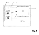
- FIG. 1 shows a common control unit 1 for occupant protection system and vehicle dynamics control with a first functional block ISS for the occupant protection system and a second functional block ABS / ESP for vehicle dynamics control.
- a common sensor cluster 2 is provided with sensors for both the occupant protection system and the vehicle dynamics control within the common control unit 1, of course, the sensor cluster 2 or individual sensors can be arranged spatially spaced at different positions in the vehicle.
- the sensor cluster 2 has an acceleration sensor X in the direction of travel and an acceleration sensor Y1 in the transverse direction for the occupant protection system with an amplitude resolution of up to 35 g.
- the acceleration signals in the travel and transverse directions could also be generated by coordinate transformation from deviating sensors, for example 45 degrees offset sensors, and provided to the algorithm.
- a second acceleration sensor Y2 is provided in the transverse direction for the driving dynamics control, which has the usual limitations for dynamic driving sensors, ie in particular a limitation of the signal amplitude to here, for example, 2g and low-pass filtering.
- This signal from the acceleration sensor Y2 is, as sketched in the FIG. 1 indicated either provided directly from the sensor to the function block ISS for the occupant protection system or forwarded via the function block ABS / ESP the vehicle dynamics control to the function block ISS for the occupant protection system.
- the signal of the sensor of the vehicle dynamics control is usually processed already sensorintem by a low-pass filtering and a limitation of the signal amplitude
- the signal of the sensor of the occupant protection system preferably in the control unit of the occupant protection system also processed with this or this predetermined signal processing step (s) and thus designed comparable to the signal of the sensor of the vehicle dynamics control.
- the signal of the sensor of the occupant protection system preferably in the control unit of the occupant protection system also processed with this or this predetermined signal processing step (s) and thus designed comparable to the signal of the sensor of the vehicle dynamics control.
- a 2-pole Bessel filtering with a cutoff frequency of 50 Hz and an amplitude limit to 2g as well suited to win a signal comparable to the signal of the vehicle dynamics control signal from the signal of the sensor of the occupant protection system.
- other filters can also be used.
- the aim is to imitate the driving dynamics signal with the crash sensor.
- the deviation of the two signals from each other is summed or integrated with a tolerance threshold compared and evaluated within the tolerance threshold, the signals as plausible. Since short-term deviations can never be ruled out, but are insignificant for the control, it is advisable to integrate the deviations over a sliding time window or to summate them just equivalently for digital signal values.
- a sliding time window is used in this embodiment with 4 ms, with time windows below 10 ms are to be preferred in order to respond to the dynamic signals sufficiently fast.
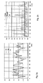
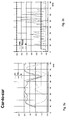
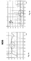
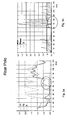
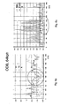
- FIGS. 2 to 7 show in each case signal waveforms at different collision types and thereby provided plausibility of the lateral acceleration signals Y1, Y2 optionally taking into account the acceleration signal X.
- the lateral acceleration on the sensor of the occupant protection system is shown in dashed lines as Y1 after its filtering and trimming to the 2g limit, the solid curve shows the lateral acceleration signal of the vehicle dynamics sensor, which is already inside the sensor due to the so limited signal range of the vehicle Sensor is only converted to 2g.
- the significantly coarser resolution of the sensor Y1 of the occupant protection system in the range up to 2 g additionally leads to a certain, tolerable deviation.
- the signal of the acceleration sensor X of the occupant protection system is indicated in the direction of travel, which can indeed be used for the evaluation of implausible areas.
- the signal X is preferably also trimmed to 2g.
- the acceleration with a sign is shown as fluctuating around the zero line between + 2g and -2g, wherein the assignment of the positive direction in the lateral acceleration sensors Y1 and Y2 to the right and left sides is insignificant.
- the signal X represents positive accelerations in the direction of travel as positive, that is to say in the case of a frontal crash, correspondingly negative accelerations in the X direction are represented.
- the course of the integrated deviation signal is shown dotted. That is, the deviations from the acceleration signal Y1 to the acceleration signal Y2 are summed over a sliding time window of, for example, 4 ms and compared with the maximum threshold shown in dashed lines. If this maximum threshold is exceeded, the acceleration signals Y1 and Y2 are no longer plausible.
- the plausibility assessment is shown as a solid line, whereby the value 0 characterizes an implausible range and the value 1 indicates the plausibility.
- FIG. 2 shows an example of the waveforms of a typically serious Misuses (60km / h, curb crossing). This shows deviations of the signals Y1 and Y2 and was therefore used for the parameterization of the plausibility criterion. While an impact at this speed and at this angle to a larger obstacle clearly leads to a tripping, it also comes in a curb crossing to significant acceleration signals in the direction of travel and transverse direction, but it is still no trigger the occupant protection device.
- the lateral acceleration signals Y1 and Y2 have a very similar course, so that the course of the time window integral ⁇ on the difference of these two signals (in FIG. 2b dotted) does not exceed the maximum threshold (Max) and thus the plausibility signal (Plausi - solid line) always maintains the value 1 associated with the fulfilled sensor plausibility. The plausibility is thus fulfilled for the entire duration of this misuse (see Fig. 2b ).
- FIG. 3 now shows in comparison to the waveforms in a side vehicle-vehicle collision, in which therefore a second vehicle ramming the side of the vehicle with the occupant protection system.
- Clearly recognizable are the relatively strong, synchronous excursions of the two acceleration signals, the deviations over the time window remain integrated within the maximum threshold.
- the lateral acceleration signals are thus plausible to one another over the entire course of the crash and allow the deployment of the occupant protection devices, in particular the side airbags.
- FIG. 4 shows analogously to FIG. 3 a classic side impact, trigger case: collision with a deformable barrier. As in FIG. 4a marked circled, occurs in a time range of about 35-45 ms from the beginning of the crash on a significant deviation of the lateral acceleration signal Y2 of the vehicle dynamics control. However, since the triggering decision could be made at a much earlier point in time by the system, the plausibility in this time range has no consequences for the triggering behavior.
- Fig. 5 now shows the signal curves in a lateral pile impact on the rear row of seats. It should be emphasized again here that the course of the lateral acceleration signals Y1 and Y2 is plausible at least in the time range which is decisive for the triggering and the implausible time range is also characterized by a strong X signal.
- Fig. 6 shows the signal curves in a partially overlapping head-on collision with a deformable obstacle (ODB - Offset deformable barrier). Partial overlap results in significant signal components in the lateral acceleration signals Y1 and Y2 despite the collision in the direction of travel. Although the lateral acceleration signals in the marked area deviate so far from each other here that the plausibility is not given, however, this time range is clearly after the time range decisive for the triggering (up to approximately 30 ms). In addition, the strong signal X can be used in the direction of travel for plausibility.
- Fig. 7 still shows the waveforms in a frontal wall collision.
- significant signal components of the lateral acceleration signals occur, which in turn, however, are plausible to one another in the triggering time domain.
- the later implausible areas are clearly after the triggering time and could also be made plausible by a strong X-signal.
- This method is thus suitable for a vehicle with a control unit for an occupant protection system and a spatially separate control unit for the vehicle dynamics control as well as for a common control unit for occupant protection system and vehicle dynamics control.
- the method may be used to validate the lateral acceleration signal of the occupant protection system without requiring paged side sensors. This considerably reduces the costs of the occupant protection system without having to forego the desired plausibility check.
- the method is applicable both for sensors for the occupant protection system and spaced at different positions in the vehicle arranged sensors for the vehicle dynamics control as well as a system with crash and driving dynamics sensor at a common location in the vehicle.
- the arrangement of the sensors in a common control unit for vehicle dynamics and crash sensor technology (sensor cluster) is possible.
Landscapes
- Engineering & Computer Science (AREA)
- Automation & Control Theory (AREA)
- Mechanical Engineering (AREA)
- Human Computer Interaction (AREA)
- Transportation (AREA)
- Air Bags (AREA)
Claims (6)
- Procédé de commande d'un système de protection d'occupants, avec prise en compte d'au moins un signal d'au moins un capteur du système de protection d'occupants
ainsi que
d'au moins un signal d'au moins un capteur d'une commande de dynamique de conduite,
les deux capteurs mesurant l'accélération transversale, et le signal du capteur de la commande de dynamique de conduite étant fourni au système de protection d'occupants après une étape prédéfinie de traitement du signal,
le signal du capteur du système de protection d'occupants étant également traité avec cette étape prédéfinie de traitement du signal, et
l'écart des deux signaux l'un par rapport à l'autre étant ensuite intégré ou respectivement cumulé à l'intérieur d'une fenêtre de temps et cet écart intégré ou respectivement cumulé étant comparé à un seuil de tolérance, et les signaux à l'intérieur du seuil de tolérance étant évalués comme plausibles. - Procédé selon la revendication 1, caractérisé en ce que l'étape prédéfinie de traitement du signal présente un filtrage passe-bas, en particulier un filtrage de Bessel à 2 pôles.
- Procédé selon une des revendications précédentes, caractérisé en ce que l'étape prédéfinie de traitement du signal présente une limitation d'amplitude.
- Procédé selon la revendication 1 ou 2, caractérisé en ce que
le système de protection d'occupants produit un premier signal d'accélération dans une première direction, et ce signal est comparé avec un signal d'accélération de la commande de dynamique de conduite également dans cette première direction, le système de protection d'occupants fournissant en plus un deuxième signal d'accélération dans une deuxième direction perpendiculaire à la première, et le premier signal d'accélération du système de protection d'occupants étant évalué comme plausible même en cas de dépassement du seuil de tolérance si le deuxième signal d'accélération ou une grandeur qui en est dérivée passe au-dessus d'un seul prédéfini. - Appareil de commande pour un système de protection d'occupants avec au moins un capteur pour le système de protection d'occupants et avec une entrée de signal pour la réception d'un signal de capteur d'un capteur de la commande de dynamique de conduite, les deux capteurs mesurant l'accélération transversale, ainsi qu'avec des moyens pour la réalisation du procédé selon une des revendications précédentes, et cela avec
des moyens pour fournir au système de protection d'occupants le signal du capteur de la commande de dynamique de conduite après une étape prédéfinie de traitement du signal,
des moyens pour traiter le signal du capteur du système de protection d'occupants également avec cette étape prédéfinie de traitement du signal et
des moyens pour intégrer ou respectivement cumuler ensuite l'écart des deux signaux l'un par rapport à l'autre à l'intérieur d'une fenêtre de temps, et pour comparer cet écart intégré ou respectivement cumulé avec un seuil de tolérance et pour évaluer comme plausibles les signaux à l'intérieur du seuil de tolérance. - Appareil de commande commun pour un système de protection d'occupants et une commande de dynamique de conduite avec au moins un capteur pour le système de protection d'occupants et au moins un capteur pour la commande de dynamique de conduite, les deux capteurs mesurant l'accélération transversale, et ainsi qu'avec des moyens pour la réalisation du procédé selon une des revendications 1-4, et cela avec
des moyens pour fournir au système de protection d'occupants le signal du capteur de la commande de dynamique de conduite après une étape prédéfinie de traitement du signal,
des moyens pour traiter le signal du capteur du système de protection d'occupants également avec cette étape prédéfinie de traitement du signal, et
des moyens pour intégrer ou respectivement cumuler ensuite l'écart des deux signaux l'un par rapport à l'autre à l'intérieur d'une fenêtre de temps, et pour comparer cet écart intégré ou respectivement cumulé avec un seuil de tolérance et pour évaluer comme plausibles les signaux à l'intérieur du seuil de tolérance.
Applications Claiming Priority (2)
| Application Number | Priority Date | Filing Date | Title |
|---|---|---|---|
| DE102010009217A DE102010009217A1 (de) | 2010-02-25 | 2010-02-25 | Verfahren zur Steuerung eines Insassenschutzsystems unter Berücksichtigung zumindest eines Signals zumindest eines Sensors einer Fahrdynamiksteuerung |
| PCT/DE2010/000978 WO2011103845A1 (fr) | 2010-02-25 | 2010-08-20 | Procédé de commande d'un système de protection de passager prenant en compte au moins un signal d'au moins un capteur d'une commande de dynamique de conduite |
Publications (2)
| Publication Number | Publication Date |
|---|---|
| EP2539190A1 EP2539190A1 (fr) | 2013-01-02 |
| EP2539190B1 true EP2539190B1 (fr) | 2014-04-02 |
Family
ID=43098923
Family Applications (1)
| Application Number | Title | Priority Date | Filing Date |
|---|---|---|---|
| EP10760239.3A Active EP2539190B1 (fr) | 2010-02-25 | 2010-08-20 | Procédé de commande d'un système de protection de passager utilisant le signal d'un capteur d'un système de stabilisation |
Country Status (4)
| Country | Link |
|---|---|
| EP (1) | EP2539190B1 (fr) |
| DE (2) | DE102010009217A1 (fr) |
| ES (1) | ES2471370T3 (fr) |
| WO (1) | WO2011103845A1 (fr) |
Families Citing this family (1)
| Publication number | Priority date | Publication date | Assignee | Title |
|---|---|---|---|---|
| DE102011084948B4 (de) * | 2011-10-21 | 2016-12-29 | Robert Bosch Gmbh | Vorrichtung bzw. ein Verfahren zur Ansteuerung von Personenschutz- und/oder Rückhaltemitteln |
Citations (1)
| Publication number | Priority date | Publication date | Assignee | Title |
|---|---|---|---|---|
| DE102007057137A1 (de) * | 2007-11-28 | 2009-06-04 | Robert Bosch Gmbh | Steuergerät und Verfahren zur Ansteuerung von Personenschutzmitteln |
Family Cites Families (11)
| Publication number | Priority date | Publication date | Assignee | Title |
|---|---|---|---|---|
| DE4436162C1 (de) * | 1994-10-10 | 1996-03-21 | Siemens Ag | System zum Regeln der Fahrstabilität eines Kraftfahrzeugs |
| DE10049905A1 (de) * | 2000-10-10 | 2001-10-25 | Bosch Gmbh Robert | Steuergerät für ein Rückhaltesystem |
| US6701788B2 (en) * | 2001-07-31 | 2004-03-09 | Kelsey-Hayes Company | Multiple output inertial sensing device |
| DE10312105A1 (de) * | 2003-03-19 | 2004-09-30 | Robert Bosch Gmbh | Vorrichtung zur Ansteuerung von Rückhaltemitteln |
| DE10317640A1 (de) * | 2003-04-17 | 2004-11-04 | Robert Bosch Gmbh | Vorrichtung zur Ansteuerung von Rückhaltemitteln |
| DE102004038000A1 (de) | 2004-08-04 | 2006-03-16 | Conti Temic Microelectronic Gmbh | Verfahren zur Bestimmung des Neigungswinkels eines Fahrzeuges und Verwendung desselben für die Erzeugung eines Auslösesignales für eine Sicherheitseinrichtung bei einem Überrollvorgang |
| DE102005015568A1 (de) * | 2005-04-05 | 2006-10-12 | Robert Bosch Gmbh | Vorrichtung zur Aufprallerkennung |
| DE102005022997A1 (de) | 2005-05-19 | 2006-11-30 | Daimlerchrysler Ag | Verfahren und Vorrichtung zur Ansteuerung eines Insassenschutzmittels |
| DE102005038227A1 (de) * | 2005-08-12 | 2007-02-15 | Robert Bosch Gmbh | Vorrichtung und Verfahren zur Seitenaufprallerkennung in einem Fahrzeug |
| DE102005049758B4 (de) * | 2005-10-14 | 2017-06-01 | Conti Temic Microelectronic Gmbh | Verfahren zur Steuerung eines Insassenschutzsystems sowie entsprechendes Insassenschutzsystem |
| DE102007047337A1 (de) * | 2007-10-04 | 2008-05-08 | Vdo Automotive Ag | Verfahren und System zum Verarbeiten von Sensorsignalen eines Kraftfahrzeugs |
-
2010
- 2010-02-25 DE DE102010009217A patent/DE102010009217A1/de not_active Withdrawn
- 2010-08-20 DE DE112010004000T patent/DE112010004000A5/de not_active Withdrawn
- 2010-08-20 EP EP10760239.3A patent/EP2539190B1/fr active Active
- 2010-08-20 ES ES10760239.3T patent/ES2471370T3/es active Active
- 2010-08-20 WO PCT/DE2010/000978 patent/WO2011103845A1/fr not_active Ceased
Patent Citations (1)
| Publication number | Priority date | Publication date | Assignee | Title |
|---|---|---|---|---|
| DE102007057137A1 (de) * | 2007-11-28 | 2009-06-04 | Robert Bosch Gmbh | Steuergerät und Verfahren zur Ansteuerung von Personenschutzmitteln |
Also Published As
| Publication number | Publication date |
|---|---|
| ES2471370T3 (es) | 2014-06-26 |
| DE112010004000A5 (de) | 2012-08-23 |
| EP2539190A1 (fr) | 2013-01-02 |
| WO2011103845A1 (fr) | 2011-09-01 |
| DE102010009217A1 (de) | 2011-08-25 |
Similar Documents
| Publication | Publication Date | Title |
|---|---|---|
| DE10065518B4 (de) | Verfahren zum Auslösen von Rückhaltemitteln in einem Kraftfahrzeug | |
| EP1258399B2 (fr) | Procédé pour l'activation d'une application de protection de passager dans un véhicule à moteur | |
| DE112007002666B4 (de) | Aktivierungsvorrichtung für ein Insassenschutzsystem | |
| DE10149112B4 (de) | Verfahren zur Bestimmung einer Auslöseentscheidung für Rückhaltemittel in einem Fahrzeug | |
| EP2054273B1 (fr) | Dispositif et procédé de commande de moyens de protection de personnes | |
| EP2315686B1 (fr) | Procédé pour déterminer un critère de gravité d'un accident à l'aide d'un signal d'accélération et d'un signal de bruit de structure | |
| DE102006048604A1 (de) | Verfahren und Vorrichtung zum Überprüfen eines Sensorsignals | |
| DE19537546B4 (de) | Aufprallerkennungsvorrichtung, insbesondere für ein Sicherheitssystem für Fahrzeuge zur Personenbeförderung | |
| EP2247470B1 (fr) | Procédé et appareil de commande pour commander des moyens de protection des personnes pour un véhicule | |
| WO2004069607A1 (fr) | Procede et dispositif pour commander un systeme de protection des occupants d'un vehicule | |
| DE10221466A1 (de) | Verfahren zur Auslösung einer Sicherheitseinrichtung in einem Kraftfahrzeug bei einem Überrollvorgang | |
| DE102008022589B3 (de) | Verfahren zum Erkennen einer Kollisionsseite bei einem Frontalaufprall mit teilweiser Überdeckung oder unter einem Winkel auf ein Kraftfahrzeug und Ansteuersystem für ein Personenschutzmittel in einem Kraftfahrzeug | |
| EP2539190B1 (fr) | Procédé de commande d'un système de protection de passager utilisant le signal d'un capteur d'un système de stabilisation | |
| WO2018149600A1 (fr) | Procédé pour l'activation d'au moins une fonction secondaire d'un système de protection des occupants d'un véhicule | |
| DE102008008850A1 (de) | Verfahren und Steuergerät zur Ansteuerung von Personenschutzmitteln für ein Fahrzeug | |
| DE102008003079B4 (de) | Verfahren und Steuergerät zur Ansteuerung von Personenschutzmitteln für ein Fahrzeug | |
| DE102014202671B4 (de) | Verfahren und Vorrichtung zum Erkennen eines Seitenaufpralls eines Objektes auf ein Fahrzeug | |
| DE102005033937A1 (de) | Verfahren und Vorrichtung zur Ansteuerung von Personenschutzmitteln | |
| DE102007024195B4 (de) | Verfahren und Steuergerät zur Ansteuerung von Personenschutzmitteln | |
| DE102021206363B4 (de) | Verfahren zur Auslösung von Insassenschutzeinrichtungen in einem Kraftfahrzeug auf Basis der Signale zumindest eines rechten und zumindest eines linken Upfrontsensors sowie des Signals zumindest eines zentral im Fahrzeug angeordneten Aufprallsensors | |
| DE102011106707B4 (de) | Verfahren zur Bewertung eines Aufpralls mittels zumindest zweier Aufprallsensoren an einem Fahrzeug | |
| DE102007002996B4 (de) | Verfahren zum Steuern eines Personenschutzsystems eines Fahrzeugs sowie entsprechende Steuereinheit | |
| DE102006030563A1 (de) | Sensoreinheit und zugehöriges Schutzsystem für ein Fahrzeug | |
| WO2022268268A1 (fr) | Procédé de déclenchement de dispositifs de protection des occupants d'un véhicule automobile sur la base des signaux d'au moins un capteur avant droit et d'au moins un capteur avant gauche ainsi que du signal d'au moins un capteur d'impact central disposé dans le véhicule | |
| DE102012024849A1 (de) | Verfahren zur Aktivierung zumindest einer Insassenschutzvorrichtung in einem Fahrzeug |
Legal Events
| Date | Code | Title | Description |
|---|---|---|---|
| PUAI | Public reference made under article 153(3) epc to a published international application that has entered the european phase |
Free format text: ORIGINAL CODE: 0009012 |
|
| 17P | Request for examination filed |
Effective date: 20120516 |
|
| AK | Designated contracting states |
Kind code of ref document: A1 Designated state(s): AL AT BE BG CH CY CZ DE DK EE ES FI FR GB GR HR HU IE IS IT LI LT LU LV MC MK MT NL NO PL PT RO SE SI SK SM TR |
|
| DAX | Request for extension of the european patent (deleted) | ||
| 17Q | First examination report despatched |
Effective date: 20130702 |
|
| GRAP | Despatch of communication of intention to grant a patent |
Free format text: ORIGINAL CODE: EPIDOSNIGR1 |
|
| INTG | Intention to grant announced |
Effective date: 20131126 |
|
| GRAS | Grant fee paid |
Free format text: ORIGINAL CODE: EPIDOSNIGR3 |
|
| GRAA | (expected) grant |
Free format text: ORIGINAL CODE: 0009210 |
|
| AK | Designated contracting states |
Kind code of ref document: B1 Designated state(s): AL AT BE BG CH CY CZ DE DK EE ES FI FR GB GR HR HU IE IS IT LI LT LU LV MC MK MT NL NO PL PT RO SE SI SK SM TR |
|
| REG | Reference to a national code |
Ref country code: GB Ref legal event code: FG4D Free format text: NOT ENGLISH |
|
| REG | Reference to a national code |
Ref country code: CH Ref legal event code: EP Ref country code: AT Ref legal event code: REF Ref document number: 659890 Country of ref document: AT Kind code of ref document: T Effective date: 20140415 |
|
| REG | Reference to a national code |
Ref country code: IE Ref legal event code: FG4D Free format text: LANGUAGE OF EP DOCUMENT: GERMAN |
|
| REG | Reference to a national code |
Ref country code: DE Ref legal event code: R096 Ref document number: 502010006554 Country of ref document: DE Effective date: 20140508 |
|
| REG | Reference to a national code |
Ref country code: ES Ref legal event code: FG2A Ref document number: 2471370 Country of ref document: ES Kind code of ref document: T3 Effective date: 20140626 |
|
| REG | Reference to a national code |
Ref country code: NL Ref legal event code: VDEP Effective date: 20140402 |
|
| REG | Reference to a national code |
Ref country code: LT Ref legal event code: MG4D |
|
| PG25 | Lapsed in a contracting state [announced via postgrant information from national office to epo] |
Ref country code: NL Free format text: LAPSE BECAUSE OF FAILURE TO SUBMIT A TRANSLATION OF THE DESCRIPTION OR TO PAY THE FEE WITHIN THE PRESCRIBED TIME-LIMIT Effective date: 20140402 Ref country code: NO Free format text: LAPSE BECAUSE OF FAILURE TO SUBMIT A TRANSLATION OF THE DESCRIPTION OR TO PAY THE FEE WITHIN THE PRESCRIBED TIME-LIMIT Effective date: 20140702 Ref country code: IS Free format text: LAPSE BECAUSE OF FAILURE TO SUBMIT A TRANSLATION OF THE DESCRIPTION OR TO PAY THE FEE WITHIN THE PRESCRIBED TIME-LIMIT Effective date: 20140802 Ref country code: CY Free format text: LAPSE BECAUSE OF FAILURE TO SUBMIT A TRANSLATION OF THE DESCRIPTION OR TO PAY THE FEE WITHIN THE PRESCRIBED TIME-LIMIT Effective date: 20140402 Ref country code: GR Free format text: LAPSE BECAUSE OF FAILURE TO SUBMIT A TRANSLATION OF THE DESCRIPTION OR TO PAY THE FEE WITHIN THE PRESCRIBED TIME-LIMIT Effective date: 20140703 Ref country code: BG Free format text: LAPSE BECAUSE OF FAILURE TO SUBMIT A TRANSLATION OF THE DESCRIPTION OR TO PAY THE FEE WITHIN THE PRESCRIBED TIME-LIMIT Effective date: 20140702 Ref country code: CZ Free format text: LAPSE BECAUSE OF FAILURE TO SUBMIT A TRANSLATION OF THE DESCRIPTION OR TO PAY THE FEE WITHIN THE PRESCRIBED TIME-LIMIT Effective date: 20140402 Ref country code: FI Free format text: LAPSE BECAUSE OF FAILURE TO SUBMIT A TRANSLATION OF THE DESCRIPTION OR TO PAY THE FEE WITHIN THE PRESCRIBED TIME-LIMIT Effective date: 20140402 Ref country code: LT Free format text: LAPSE BECAUSE OF FAILURE TO SUBMIT A TRANSLATION OF THE DESCRIPTION OR TO PAY THE FEE WITHIN THE PRESCRIBED TIME-LIMIT Effective date: 20140402 |
|
| PG25 | Lapsed in a contracting state [announced via postgrant information from national office to epo] |
Ref country code: HR Free format text: LAPSE BECAUSE OF FAILURE TO SUBMIT A TRANSLATION OF THE DESCRIPTION OR TO PAY THE FEE WITHIN THE PRESCRIBED TIME-LIMIT Effective date: 20140402 Ref country code: LV Free format text: LAPSE BECAUSE OF FAILURE TO SUBMIT A TRANSLATION OF THE DESCRIPTION OR TO PAY THE FEE WITHIN THE PRESCRIBED TIME-LIMIT Effective date: 20140402 Ref country code: SE Free format text: LAPSE BECAUSE OF FAILURE TO SUBMIT A TRANSLATION OF THE DESCRIPTION OR TO PAY THE FEE WITHIN THE PRESCRIBED TIME-LIMIT Effective date: 20140402 Ref country code: PL Free format text: LAPSE BECAUSE OF FAILURE TO SUBMIT A TRANSLATION OF THE DESCRIPTION OR TO PAY THE FEE WITHIN THE PRESCRIBED TIME-LIMIT Effective date: 20140402 |
|
| PG25 | Lapsed in a contracting state [announced via postgrant information from national office to epo] |
Ref country code: PT Free format text: LAPSE BECAUSE OF FAILURE TO SUBMIT A TRANSLATION OF THE DESCRIPTION OR TO PAY THE FEE WITHIN THE PRESCRIBED TIME-LIMIT Effective date: 20140804 |
|
| REG | Reference to a national code |
Ref country code: DE Ref legal event code: R097 Ref document number: 502010006554 Country of ref document: DE |
|
| PG25 | Lapsed in a contracting state [announced via postgrant information from national office to epo] |
Ref country code: DK Free format text: LAPSE BECAUSE OF FAILURE TO SUBMIT A TRANSLATION OF THE DESCRIPTION OR TO PAY THE FEE WITHIN THE PRESCRIBED TIME-LIMIT Effective date: 20140402 Ref country code: EE Free format text: LAPSE BECAUSE OF FAILURE TO SUBMIT A TRANSLATION OF THE DESCRIPTION OR TO PAY THE FEE WITHIN THE PRESCRIBED TIME-LIMIT Effective date: 20140402 Ref country code: RO Free format text: LAPSE BECAUSE OF FAILURE TO SUBMIT A TRANSLATION OF THE DESCRIPTION OR TO PAY THE FEE WITHIN THE PRESCRIBED TIME-LIMIT Effective date: 20140402 Ref country code: SK Free format text: LAPSE BECAUSE OF FAILURE TO SUBMIT A TRANSLATION OF THE DESCRIPTION OR TO PAY THE FEE WITHIN THE PRESCRIBED TIME-LIMIT Effective date: 20140402 |
|
| PLBE | No opposition filed within time limit |
Free format text: ORIGINAL CODE: 0009261 |
|
| STAA | Information on the status of an ep patent application or granted ep patent |
Free format text: STATUS: NO OPPOSITION FILED WITHIN TIME LIMIT |
|
| 26N | No opposition filed |
Effective date: 20150106 |
|
| PG25 | Lapsed in a contracting state [announced via postgrant information from national office to epo] |
Ref country code: LU Free format text: LAPSE BECAUSE OF FAILURE TO SUBMIT A TRANSLATION OF THE DESCRIPTION OR TO PAY THE FEE WITHIN THE PRESCRIBED TIME-LIMIT Effective date: 20140820 Ref country code: MC Free format text: LAPSE BECAUSE OF FAILURE TO SUBMIT A TRANSLATION OF THE DESCRIPTION OR TO PAY THE FEE WITHIN THE PRESCRIBED TIME-LIMIT Effective date: 20140402 |
|
| REG | Reference to a national code |
Ref country code: CH Ref legal event code: PL |
|
| REG | Reference to a national code |
Ref country code: DE Ref legal event code: R097 Ref document number: 502010006554 Country of ref document: DE Effective date: 20150106 |
|
| PG25 | Lapsed in a contracting state [announced via postgrant information from national office to epo] |
Ref country code: CH Free format text: LAPSE BECAUSE OF NON-PAYMENT OF DUE FEES Effective date: 20140831 Ref country code: LI Free format text: LAPSE BECAUSE OF NON-PAYMENT OF DUE FEES Effective date: 20140831 Ref country code: BE Free format text: LAPSE BECAUSE OF NON-PAYMENT OF DUE FEES Effective date: 20140831 |
|
| REG | Reference to a national code |
Ref country code: IE Ref legal event code: MM4A |
|
| PG25 | Lapsed in a contracting state [announced via postgrant information from national office to epo] |
Ref country code: SI Free format text: LAPSE BECAUSE OF FAILURE TO SUBMIT A TRANSLATION OF THE DESCRIPTION OR TO PAY THE FEE WITHIN THE PRESCRIBED TIME-LIMIT Effective date: 20140402 |
|
| REG | Reference to a national code |
Ref country code: FR Ref legal event code: PLFP Year of fee payment: 6 |
|
| PG25 | Lapsed in a contracting state [announced via postgrant information from national office to epo] |
Ref country code: IE Free format text: LAPSE BECAUSE OF NON-PAYMENT OF DUE FEES Effective date: 20140820 |
|
| PG25 | Lapsed in a contracting state [announced via postgrant information from national office to epo] |
Ref country code: SM Free format text: LAPSE BECAUSE OF FAILURE TO SUBMIT A TRANSLATION OF THE DESCRIPTION OR TO PAY THE FEE WITHIN THE PRESCRIBED TIME-LIMIT Effective date: 20140402 |
|
| PG25 | Lapsed in a contracting state [announced via postgrant information from national office to epo] |
Ref country code: MT Free format text: LAPSE BECAUSE OF FAILURE TO SUBMIT A TRANSLATION OF THE DESCRIPTION OR TO PAY THE FEE WITHIN THE PRESCRIBED TIME-LIMIT Effective date: 20140402 |
|
| PG25 | Lapsed in a contracting state [announced via postgrant information from national office to epo] |
Ref country code: HU Free format text: LAPSE BECAUSE OF FAILURE TO SUBMIT A TRANSLATION OF THE DESCRIPTION OR TO PAY THE FEE WITHIN THE PRESCRIBED TIME-LIMIT; INVALID AB INITIO Effective date: 20100820 Ref country code: TR Free format text: LAPSE BECAUSE OF FAILURE TO SUBMIT A TRANSLATION OF THE DESCRIPTION OR TO PAY THE FEE WITHIN THE PRESCRIBED TIME-LIMIT Effective date: 20140402 |
|
| REG | Reference to a national code |
Ref country code: FR Ref legal event code: PLFP Year of fee payment: 7 |
|
| REG | Reference to a national code |
Ref country code: AT Ref legal event code: MM01 Ref document number: 659890 Country of ref document: AT Kind code of ref document: T Effective date: 20150820 |
|
| PG25 | Lapsed in a contracting state [announced via postgrant information from national office to epo] |
Ref country code: AT Free format text: LAPSE BECAUSE OF NON-PAYMENT OF DUE FEES Effective date: 20150820 |
|
| REG | Reference to a national code |
Ref country code: FR Ref legal event code: PLFP Year of fee payment: 8 |
|
| PG25 | Lapsed in a contracting state [announced via postgrant information from national office to epo] |
Ref country code: MK Free format text: LAPSE BECAUSE OF FAILURE TO SUBMIT A TRANSLATION OF THE DESCRIPTION OR TO PAY THE FEE WITHIN THE PRESCRIBED TIME-LIMIT Effective date: 20140402 |
|
| REG | Reference to a national code |
Ref country code: FR Ref legal event code: PLFP Year of fee payment: 9 |
|
| PG25 | Lapsed in a contracting state [announced via postgrant information from national office to epo] |
Ref country code: AL Free format text: LAPSE BECAUSE OF FAILURE TO SUBMIT A TRANSLATION OF THE DESCRIPTION OR TO PAY THE FEE WITHIN THE PRESCRIBED TIME-LIMIT Effective date: 20140402 |
|
| REG | Reference to a national code |
Ref country code: DE Ref legal event code: R081 Ref document number: 502010006554 Country of ref document: DE Owner name: CONTINENTAL AUTOMOTIVE TECHNOLOGIES GMBH, DE Free format text: FORMER OWNER: CONTINENTAL AUTOMOTIVE GMBH, 30165 HANNOVER, DE Ref country code: DE Ref legal event code: R081 Ref document number: 502010006554 Country of ref document: DE Owner name: AUMOVIO GERMANY GMBH, DE Free format text: FORMER OWNER: CONTINENTAL AUTOMOTIVE GMBH, 30165 HANNOVER, DE |
|
| REG | Reference to a national code |
Ref country code: GB Ref legal event code: 732E Free format text: REGISTERED BETWEEN 20230223 AND 20230301 |
|
| REG | Reference to a national code |
Ref country code: DE Ref legal event code: R081 Ref document number: 502010006554 Country of ref document: DE Owner name: CONTINENTAL AUTOMOTIVE TECHNOLOGIES GMBH, DE Free format text: FORMER OWNER: CONTINENTAL AUTOMOTIVE TECHNOLOGIES GMBH, 30165 HANNOVER, DE Ref country code: DE Ref legal event code: R081 Ref document number: 502010006554 Country of ref document: DE Owner name: AUMOVIO GERMANY GMBH, DE Free format text: FORMER OWNER: CONTINENTAL AUTOMOTIVE TECHNOLOGIES GMBH, 30165 HANNOVER, DE |
|
| REG | Reference to a national code |
Ref country code: ES Ref legal event code: PC2A Owner name: CONTINENTAL AUTOMOTIVE TECHNOLOGIES GMBH Effective date: 20240410 |
|
| PGFP | Annual fee paid to national office [announced via postgrant information from national office to epo] |
Ref country code: GB Payment date: 20240826 Year of fee payment: 15 |
|
| PGFP | Annual fee paid to national office [announced via postgrant information from national office to epo] |
Ref country code: FR Payment date: 20240829 Year of fee payment: 15 |
|
| PGFP | Annual fee paid to national office [announced via postgrant information from national office to epo] |
Ref country code: ES Payment date: 20240927 Year of fee payment: 15 |
|
| PGFP | Annual fee paid to national office [announced via postgrant information from national office to epo] |
Ref country code: IT Payment date: 20240827 Year of fee payment: 15 |
|
| REG | Reference to a national code |
Ref country code: DE Ref legal event code: R084 Ref document number: 502010006554 Country of ref document: DE |
|
| PGFP | Annual fee paid to national office [announced via postgrant information from national office to epo] |
Ref country code: DE Payment date: 20250831 Year of fee payment: 16 |
|
| REG | Reference to a national code |
Ref country code: DE Ref legal event code: R081 Ref document number: 502010006554 Country of ref document: DE Owner name: AUMOVIO GERMANY GMBH, DE Free format text: FORMER OWNER: CONTINENTAL AUTOMOTIVE TECHNOLOGIES GMBH, 30175 HANNOVER, DE |