EP2539196B1 - Druckluftaufbereitungseinrichtung für kraftfahrzeuge - Google Patents
Druckluftaufbereitungseinrichtung für kraftfahrzeuge Download PDFInfo
- Publication number
- EP2539196B1 EP2539196B1 EP20100787294 EP10787294A EP2539196B1 EP 2539196 B1 EP2539196 B1 EP 2539196B1 EP 20100787294 EP20100787294 EP 20100787294 EP 10787294 A EP10787294 A EP 10787294A EP 2539196 B1 EP2539196 B1 EP 2539196B1
- Authority
- EP
- European Patent Office
- Prior art keywords
- valve
- line
- regeneration
- pressure
- compressed air
- Prior art date
- Legal status (The legal status is an assumption and is not a legal conclusion. Google has not performed a legal analysis and makes no representation as to the accuracy of the status listed.)
- Revoked
Links
- 230000008929 regeneration Effects 0.000 claims description 190
- 238000011069 regeneration method Methods 0.000 claims description 190
- 238000001035 drying Methods 0.000 claims description 51
- 230000008878 coupling Effects 0.000 claims description 14
- 238000010168 coupling process Methods 0.000 claims description 14
- 238000005859 coupling reaction Methods 0.000 claims description 14
- 238000002360 preparation method Methods 0.000 claims description 14
- 238000011144 upstream manufacturing Methods 0.000 claims 1
- 230000001276 controlling effect Effects 0.000 description 10
- 230000001419 dependent effect Effects 0.000 description 10
- 238000010586 diagram Methods 0.000 description 5
- 238000013022 venting Methods 0.000 description 5
- 238000004378 air conditioning Methods 0.000 description 3
- 238000010521 absorption reaction Methods 0.000 description 2
- 239000003463 adsorbent Substances 0.000 description 2
- 230000008901 benefit Effects 0.000 description 2
- 239000002274 desiccant Substances 0.000 description 2
- 230000008054 signal transmission Effects 0.000 description 2
- XLYOFNOQVPJJNP-UHFFFAOYSA-N water Substances O XLYOFNOQVPJJNP-UHFFFAOYSA-N 0.000 description 2
- 230000004913 activation Effects 0.000 description 1
- 230000000903 blocking effect Effects 0.000 description 1
- 238000009530 blood pressure measurement Methods 0.000 description 1
- 238000007664 blowing Methods 0.000 description 1
- 230000008859 change Effects 0.000 description 1
- 238000009833 condensation Methods 0.000 description 1
- 230000005494 condensation Effects 0.000 description 1
- 230000007797 corrosion Effects 0.000 description 1
- 238000005260 corrosion Methods 0.000 description 1
- 230000007423 decrease Effects 0.000 description 1
- 230000018109 developmental process Effects 0.000 description 1
- 239000000284 extract Substances 0.000 description 1
- 239000012530 fluid Substances 0.000 description 1
- 230000008014 freezing Effects 0.000 description 1
- 238000007710 freezing Methods 0.000 description 1
- 230000000977 initiatory effect Effects 0.000 description 1
- 238000005259 measurement Methods 0.000 description 1
- 238000005086 pumping Methods 0.000 description 1
- 230000001105 regulatory effect Effects 0.000 description 1
- 230000004044 response Effects 0.000 description 1
- 238000004904 shortening Methods 0.000 description 1
- 210000002023 somite Anatomy 0.000 description 1
- 238000001179 sorption measurement Methods 0.000 description 1
- 238000009423 ventilation Methods 0.000 description 1
Images


Classifications
-
- B—PERFORMING OPERATIONS; TRANSPORTING
- B60—VEHICLES IN GENERAL
- B60T—VEHICLE BRAKE CONTROL SYSTEMS OR PARTS THEREOF; BRAKE CONTROL SYSTEMS OR PARTS THEREOF, IN GENERAL; ARRANGEMENT OF BRAKING ELEMENTS ON VEHICLES IN GENERAL; PORTABLE DEVICES FOR PREVENTING UNWANTED MOVEMENT OF VEHICLES; VEHICLE MODIFICATIONS TO FACILITATE COOLING OF BRAKES
- B60T17/00—Component parts, details, or accessories of power brake systems not covered by groups B60T8/00, B60T13/00 or B60T15/00, or presenting other characteristic features
- B60T17/02—Arrangements of pumps or compressors, or control devices therefor
-
- B—PERFORMING OPERATIONS; TRANSPORTING
- B60—VEHICLES IN GENERAL
- B60T—VEHICLE BRAKE CONTROL SYSTEMS OR PARTS THEREOF; BRAKE CONTROL SYSTEMS OR PARTS THEREOF, IN GENERAL; ARRANGEMENT OF BRAKING ELEMENTS ON VEHICLES IN GENERAL; PORTABLE DEVICES FOR PREVENTING UNWANTED MOVEMENT OF VEHICLES; VEHICLE MODIFICATIONS TO FACILITATE COOLING OF BRAKES
- B60T17/00—Component parts, details, or accessories of power brake systems not covered by groups B60T8/00, B60T13/00 or B60T15/00, or presenting other characteristic features
- B60T17/002—Air treatment devices
-
- B—PERFORMING OPERATIONS; TRANSPORTING
- B60—VEHICLES IN GENERAL
- B60T—VEHICLE BRAKE CONTROL SYSTEMS OR PARTS THEREOF; BRAKE CONTROL SYSTEMS OR PARTS THEREOF, IN GENERAL; ARRANGEMENT OF BRAKING ELEMENTS ON VEHICLES IN GENERAL; PORTABLE DEVICES FOR PREVENTING UNWANTED MOVEMENT OF VEHICLES; VEHICLE MODIFICATIONS TO FACILITATE COOLING OF BRAKES
- B60T17/00—Component parts, details, or accessories of power brake systems not covered by groups B60T8/00, B60T13/00 or B60T15/00, or presenting other characteristic features
- B60T17/04—Arrangements of piping, valves in the piping, e.g. cut-off valves, couplings or air hoses
-
- B—PERFORMING OPERATIONS; TRANSPORTING
- B60—VEHICLES IN GENERAL
- B60T—VEHICLE BRAKE CONTROL SYSTEMS OR PARTS THEREOF; BRAKE CONTROL SYSTEMS OR PARTS THEREOF, IN GENERAL; ARRANGEMENT OF BRAKING ELEMENTS ON VEHICLES IN GENERAL; PORTABLE DEVICES FOR PREVENTING UNWANTED MOVEMENT OF VEHICLES; VEHICLE MODIFICATIONS TO FACILITATE COOLING OF BRAKES
- B60T17/00—Component parts, details, or accessories of power brake systems not covered by groups B60T8/00, B60T13/00 or B60T15/00, or presenting other characteristic features
- B60T17/18—Safety devices; Monitoring
-
- Y—GENERAL TAGGING OF NEW TECHNOLOGICAL DEVELOPMENTS; GENERAL TAGGING OF CROSS-SECTIONAL TECHNOLOGIES SPANNING OVER SEVERAL SECTIONS OF THE IPC; TECHNICAL SUBJECTS COVERED BY FORMER USPC CROSS-REFERENCE ART COLLECTIONS [XRACs] AND DIGESTS
- Y10—TECHNICAL SUBJECTS COVERED BY FORMER USPC
- Y10S—TECHNICAL SUBJECTS COVERED BY FORMER USPC CROSS-REFERENCE ART COLLECTIONS [XRACs] AND DIGESTS
- Y10S55/00—Gas separation
- Y10S55/17—Compressed air water removal
-
- Y—GENERAL TAGGING OF NEW TECHNOLOGICAL DEVELOPMENTS; GENERAL TAGGING OF CROSS-SECTIONAL TECHNOLOGIES SPANNING OVER SEVERAL SECTIONS OF THE IPC; TECHNICAL SUBJECTS COVERED BY FORMER USPC CROSS-REFERENCE ART COLLECTIONS [XRACs] AND DIGESTS
- Y10—TECHNICAL SUBJECTS COVERED BY FORMER USPC
- Y10T—TECHNICAL SUBJECTS COVERED BY FORMER US CLASSIFICATION
- Y10T137/00—Fluid handling
- Y10T137/2496—Self-proportioning or correlating systems
- Y10T137/2559—Self-controlled branched flow systems
- Y10T137/2574—Bypass or relief controlled by main line fluid condition
- Y10T137/2605—Pressure responsive
- Y10T137/2622—Bypass or relief valve responsive to pressure downstream of outlet valve
Definitions
- the invention relates to a compressed air treatment device with a compressed air leading pressure line, in which in succession a drying device and a check valve are arranged, wherein a tikbetätigbares supply control upon application of the control pressure, the compressed air supply to the drying device prevents, according to the preamble of claim 1 and a motor vehicle with such compressed air control device.
- a compressed air brake system which must be supplied with compressed air.
- the compressed air is usually provided by a compressor, which sucks air from the atmosphere and delivers a stream of compressed air into the pressure line. Because airborne moisture can condense and cause corrosion, significantly shortening the life of components, the compressed air is dried after leaving the compressor before it is fed into the pipeline network.
- a dryer unit is arranged in the pressure line. It is known to arrange supply controls at the entrance of the pressure line to turn on or off the supply of compressed air by the compressor to control the pressure in the pressure line and thus in the consumer network.
- the supply control element may be a compressed air-operated control input of the compressor.
- DE 196 38 837B4 and WO 2007/142008 A1 discloses a pressure medium processing device which provides for the pressure medium supply to a compressor and a compressor associated with the 3/2-way valve as a feed control element.
- the continuous generated compressed air flow may be supplied via the supply control valve either to the downstream elements of the pressure processing device or atmosphere.
- the supply control valve can be actuated by means of its control input by compressed air.
- This supply control valve, an air dryer and a check valve are connected downstream of the known device. To the check valve while a multi-circuit protection valve is connected, to which the individual pressure medium circuits of the pressure medium system can be connected.
- the supply control valve is connected to a pressure regulating device, which can connect a supply line branching off behind the check valve from the pressure line to the control input of the supply control valve in order to prevent the supply of compressed air to the pressure line.
- the pressure control device in the known arrangement consists essentially of a pressure-actuated governor valve and an electrically actuated control valve.
- a first control input of the governor valve is connected to the supply line and works against a permanent restoring force of a valve spring.
- the output of the governor valve is connected to the supply control valve.
- the electrically actuated control valve is also connected to the supply line with its inlet and has its outlet connected to a second control input of the governor valve, the second control input counteracting the first control input of the governor valve.
- the electrically actuable control valve or its control input is connected via an electrical line to an electronic control unit.
- the control unit generates a control signal for controlling the electric valve as a function of a pressure measurement in the supply line and thus the pressure line.
- the electrically actuated valve acts as a pilot to the governor valve and causes the governor valve to be switched to affect the compressed air supply to the pressure line.
- the known device can maintain an emergency mode in case of power failure and failure of the control valve, the supply control is pressure-dependent alone.
- the electrically actuated valve switches to the non-continuous switching position, so that the second control input of the governor valve is also not actuated.
- the governor valve then connects the supply line to the supply control valve when the pressure in the discharge line, and therefore the supply line, through the first control port of the governor valve overcomes the opposing spring force. Adjusting the restoring force of the governor valve valve spring determines the intended governor switching pressure, which is maintained by the governor via the compressed air supply circuit.
- the known compressed air treatment device can maintain a pressure-dependent control of the working pressure via the governor valve in an emergency mode in case of failure of the electrical control energy.
- An unlimited onward journey of the motor vehicle in emergency mode is not possible with the known compressed air conditioning device, since after failure of the electrical control energy very quickly decreases the quality of the compressed air treatment.
- the present invention has the object, a compressed air treatment device of the generic type such that an unlimited continuation of the motor vehicle in case of failure of the electrical control of the valves of the compressed air processing device is possible.
- the invention is based on the finding that the drying device required for air treatment extracts the moisture from the compressed air flowing through condensation and adsorption and that the adsorbent in the drying device has a limited water absorption capacity.
- the drying device must therefore be regenerated at certain intervals. Switches the known device for controlling the compressed air treatment device in case of failure of the electrical control energy in the emergency mode, so while initially a driving operation of the motor vehicle is maintained. However, the water absorption capacity of the drying device is rapidly exhausted, so that the function of the compressed air treatment device is no longer guaranteed.
- the regeneration of the drying device is regularly carried out even in case of failure of the electrical power supply of the control of the valves of the compressed air treatment, since the regeneration is controlled by the governor valve still active in case of failure of the electrical power supply.
- a motor vehicle equipped with the compressed air treatment device according to the invention can therefore continue its journey almost indefinitely.
- the governor valve takes over the control of both the compressed air treatment and the regeneration of the drying device in the de-energized operation.
- a governor valve is a pressure-actuated valve that controls the supply of compressed air, and on whose control input acts the system pressure generated by the compressed-air treatment device for the connected pneumatic circuits.
- a pilot control of the governor valve is provided if a second control input of the governor valve, which counteracts the first control input, depending on the pilot-operated solenoid valve with the system pressure can be acted upon.
- the governor valve which is precontrolled by an electrically actuated solenoid valve during electrical operation, controls the compressed air treatment at a high pressure level during electrical operation.
- the governor valve Upon failure of the electrical energy and consequent failure of pilot control, the governor valve responds when pressure is applied which overcomes the mechanical restoring force of the governor valve, such as a spring force.
- the second pressure level at which the governor valve responds in the event of a power failure is lower than the high pressure level with electrically operated pilot control, so that if the electrical supply fails, further operation of the compressed air treatment device takes place at a lower pressure level.
- a supply connection of the governor valve is connected to a supply line, which branches off from a system pressure line connecting to the pressure line.
- the pressure line and the system pressure line are separated by a check valve.
- a work port of the governor valve is connected to a pressure-actuatable supply control element which, when the control pressure is applied, prevents the compressed air supply to the drying device and allows regeneration.
- the connection of a valve is to be understood as a working connection which, depending on the valve position, can be connected to the supply connection of the valve, wherein the supply connection is that connection of the valve which is constantly pressurized and serves for the supply of compressed air. If a valve has a vent connection, this is such a connection, which can be connected to the working connection as an alternative to the supply connection.
- the work port and the supply connection of the governor valve are connected by the first control input of the governor valve, which is connected to the supply line and works against a permanent restoring force.
- a regeneration line connected to the governor valve and a vent line are provided.
- the regeneration line for supplying regeneration air for the drying device opens in the flow direction of the pressure line behind the drying device in the pressure line.
- the vent line branches in the flow direction before the drying device from the pressure line and is released during the regeneration.
- the regeneration air flow takes the moisture out of the drying device. It can be discharged through the vent line, which branches off in the flow direction before the drying device from the pressure line.
- the regeneration line is expediently linked between the drying device and the check valve to the pressure line, so that for regeneration of the dryer compressed air from the system containers, bypassing the check valve can flow back.
- a regeneration line between the governor valve and the pressure line can be carried out with simple means, a regeneration of the drying device with compressed air from the system containers and dispensed on a separate regeneration tank for the drying device.
- the regeneration air is taken from a supply line which branches off behind the check valve of the pressure line from the system pressure line.
- the supply line thus assumes both the function of supplying regeneration air and the pressure-dependent control of the governor valve in current-free operation.
- the governor valve in its continuous position prevents the supply of compressed air to the drying device by releasing the vent line.
- a pressure-actuated vent valve is arranged in the vent line, the control input is fluidly connected to the regeneration line.
- the vent line is opened only after initiation of regeneration by connecting the regeneration line with the supply line.
- the vent valve In mechanical operation, that is without electrical supply to the valves, the vent valve also works as a feed control element for the compressed air supply in the pressure line.
- the vent line When the vent line is open, the injected compressed air flow of a compressor is discharged through the vent line.
- the opening pressure of the vent valve is matched to the governor valve set pressure so that venting the supply line through the governor valve will safely open the vent valve.
- Precise control of the regeneration is possible in an advantageous embodiment of the electrical control of the compressed air treatment device when the electrically actuated solenoid valve, which pre-controls the governor valve, is arranged as a regeneration valve controlling the air flow in the regeneration line.
- a supply port of the regeneration valve is connected to the supply line and connectable by switching an electrical control input to a working port, which is connected to the second control input of the governor valve.
- the second control input counteracts the first control input of the governor valve.
- the governor valve is thereby precontrolled by the regeneration valve, so that the regeneration takes place with appropriate switching of the regeneration valve and in case of failure of the electrical power supply, the governor valve takes over the control.
- a further electrically actuated solenoid valve is arranged as the compressed air supply controlling compressor valve, whereby the regeneration operation of the compressed air processing device is decoupled in electrical control of the pressure control.
- the compressor valve is arranged for this purpose between the supply line and a control input of a supply control element. In normal operation of the compressed air treatment device, the regeneration can thus be carried out at controllable time intervals by switching the regeneration valve.
- the pressure control is released therefrom by switching the compressor valve to the continuous position by supplying an electrical signal and thereby connecting a working port of the compressor valve connected to the supply control member to a supply port.
- the compressor control valve associated feed control is arranged in the pressure line in the flow direction before the drying device and controls the supply of compressed air into the pressure line.
- a pressure actuatable control switch of the compressor forms the feed control element, so that the compressor is controlled directly.
- a pressure-actuatable control outlet of the compressor may also be provided as a feed control element be, which directs the request for the pneumatic control signal, the compressor air flow into the atmosphere.
- a separate 3/2-way valve in the pressure line forms the supply control element in electrical control of the compressed air processing device.
- the vent valve keeps the vent line closed, so that pressure losses in the pressure line are avoided. If the electrical power supply of the compressed air conditioning device and thus the circuit of the compressed air supply via the compressor valve fail, the vent valve forms the supply control of the compressed air processing device. In de-energized backup operation, the governor valve opens the vent valve upon reaching the predetermined switch-off pressure in the supply line so that the compressed air flow from the compressor is vented through the vent line. Since the governor valve closes only after a certain pressure hysteresis, the vent valve remains open until the system pressure drops below a switchback pressure determined by the cutoff pressure minus the hysteresis.
- the vent valve may be a simply designed 2/2-way valve whose control input under the pressure of the regeneration line against a spring force, the blocking of the vent line cancels and the vent line switches to continuous.
- the de-energized backup operation when the cut-off pressure is reached, the regeneration of the drying agent is initiated by air flowing back. Again, this regeneration is performed until the governor valve closes again, that is, until the system pressure falls below the shutdown pressure minus hysteresis.
- a check valve is arranged in the regeneration line, the pressure control valves are reliably protected from the pressure of the pressure line and an undesired outflow from the pressure line is avoided.
- a throttle element is arranged in the regeneration line, the compressed air flowing back from the system containers during the regeneration is released to the appropriate pressure level before being fed to the drier.
- the throttle element can be designed as a diaphragm or in an advantageous development as a switchable throttle valve.
- an assembly can be made available as a basis for electrically and mechanically controlled compressed air treatment devices.
- additional components are added to the essentially identical basic module and possibly connected differently
- the regeneration valve is designed as a 3/2-way valve, the third port acts as a vent, so that is vented by simple means after regeneration of the drying device, the second control input of the governor valve.
- the 3/2-way regeneration valve connects the control port of the governor valve to the vent line in the de-energized switch position so that control signal to the regeneration valve and regeneration valve to second switch immediately applies control pressure to the governor valve control input is placed.
- both electrically actuable solenoid valves ie regeneration valve and compressor valve
- an electronic control unit is thereby inputting suitable measurement parameters and predefining the previously determined optimal control values, so that an optimal activation of the regeneration valve or of the compressor valve for the control of the compressed air supply can take place.
- the compressed air treatment device falls into emergency operation (backup), whereby according to the invention the governor valve takes over the pressure control and the control of the dryer regeneration.
- the regeneration valve can be designed with an opening diameter of 1 mm to ensure the pneumatic actuation of the governor valve.
- an opening diameter of 1.6 mm is considered advantageous in order to ensure safe switching of the supply control element and of the pressure line or the controllable pressure outlet of the compressor to ensure.
- the governor valve is advantageously equipped with a larger opening diameter than the electrically actuated solenoid valves to ensure a sufficient flow of regeneration air flow.
- a value of about 2 mm is considered advantageous.
- the flow of regeneration air is determined by means of a switchable by pressure throttle valve whose control input is connected to the regeneration valve.
- the regeneration valve acts as long as it acts in its actuated state, the Governor valve and pre-controls, also on the throttle valve and can, for example, the intended for regeneration operation passage cross section of the throttle valve off.
- the switchable throttle valve allows a switchable change in the passage of the regeneration line, so that a variety of attachment possibilities for the refinement and variation of the pressure control and regeneration control is given in normal operation with electrical control signals.
- the switchable throttle valve has a switchable by pressure actuation coupling input, which is connected to the working port of the compressor valve and against the operation of the throttle valve by the control input and counter to the restoring force of a valve spring -wirkt.
- the regeneration operation is linked in an electrically controlled air treatment device directly to the shutdown of the compressed air supply in the pressure line. If, after a regeneration, the regeneration valve is acted upon again with an electrical switching signal, the pressure forces of the oppositely acting control inputs of the throttle valve cancel each other out and the valve spring switches the throttle valve into the second switching position, which is provided for the remaining operating modes outside the regeneration mode.
- the switchable throttle valve has two switching states with different passage cross sections, so that an optimum passage cross section for normal operation of the device and control of the regeneration via the regeneration valve can be selected.
- the optimum passage cross-section is provided for the backup operation when controlling via the governor valve.
- the passage cross section in the unactuated state of the throttle valve that is to say the passage cross section provided for the regeneration in the backup mode, is smaller than the passage cross section in the actuated state for the electrical control operation.
- the governor valve In backup mode, the governor valve maintains system pressure between the cutoff pressure and the switchback pressure resulting from the cutoff pressure minus hysteresis. Due to the simultaneous regeneration escapes in this mode permanently compressed air from the system. Therefore, a smaller cross-section is advantageous in order to avoid too rapid a drop in system pressure, thus saving energy necessary for refilling to shut-off pressure.
- a passage cross section of about 1.5 mm has proven to be useful.
- a smaller passage cross-section of about 0.5 mm is considered sufficient.
- the switchable throttle valve is arranged in a further advantageous embodiment of the invention alternatively to the arrangement in the regeneration line in a parallel to the regeneration line and in the flow direction behind the drying device in the pressure line opening connecting line.
- the connecting line can be connected to the supply line by means of the compressor valve for the compressed air control.
- the working port of the compressor valve is connected to either the supply port of the throttle valve or a pressure-dependent coupling input of the throttle valve, wherein the second variant of the supply port of the throttle valve is connected to the supply line.
- the governor valve assumes the pressure-dependent regeneration circuit as already described.
- the compressed air flows through the regeneration line for regeneration, bypassing the throttle valve.
- Another advantage of the arrangement of the throttle valve in a parallel connection line is the possibility of an optimal cold dump with reduced throughput compared to the electrically controlled regeneration mode.
- an electrical control signal is supplied, so that the governor valve releases the flow path through the vent line under the pressure of the supply line.
- the blow-off is set in the meantime, in particular at cold ambient temperatures of the electrical control unit to counteract icing of the pressure line and the units arranged therein and the vent valve by means of warm air from the compressor.
- blowdown mode the return flow only takes place via the regeneration line. This results in a lower mass flow through the dryer, so that the flow through the drying device is limited in the reverse direction.
- the regeneration is coupled in normal operation with electrical control directly to the shutdown of the compressed air supply by the compressor.
- the compressor valve is blocked by the same valve member, namely that of the compressor valve, without any delay, the flow path in the reverse direction.
- a direct flow of the regeneration air to the dryer without flow through other valves than the throttle valve is given according to a further embodiment of the invention, when the supply connection of the throttle valve in the connecting line is connected to the supply line.
- a second control input of the throttle valve which counteracts the first, connected to the regeneration valve, control input is connected to the working port of the compressor valve.
- the continuous position of the compressor valve thus affects the pressure at the supply port of the compressor valve, so the system pressure on the coupling input of the throttle valve.
- An advantage of the supply of the connecting line directly from the supply line is also that the working port of the compressor valve is used only for signal transmission and therefore the supply control of the compressor can be switched safely. Also, the compressor valve structurally smaller dimensions and thereby costs can be saved.
- the throttle element in the regeneration line may be a diaphragm with a smaller passage cross section than the cross section of the throttle valve, so that the desired reduced air flow in the opposite direction of flow occurs in Abblas compassion, which is sufficient in backup mode for a regeneration.
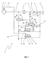
- Fig. 1 shows an electrically controlled compressed air treatment device 1 with a pressure line 2, in the same as in the compressed air treatment devices according to the Fig.2 . 3 . 4 . 5 in succession, a drying device 4 and a check valve 5 are arranged one behind the other.
- a check valve 5 To the check valve 5 is not shown here safety valve or multi-circuit protection valve connected to the individual pressure medium circuits such as the pressure medium circuits of an air brake system of a motor vehicle can be connected. These pressure medium circuits are not shown in the drawing figures.
- the compressed air supply takes place in all embodiments via a compressor 6.
- a druckbetätigbarer control switch 7 of the compressor 6 forms a feed control of the compressed air processing device, so that the compressed air supply is connected directly to the pressure line 2.
- a pressure-actuated control outlet of the compressor may be provided, which dissipates the compressor flow when actuated or a separate 3/2-way valve in the pressure line.
- the compressor 6 sucks air from the atmosphere and outputs a compressed air flow in the pressure line 2 from.
- the control switch 7 can be actuated by compressed air via a compressor control line 8. As soon as the control pressure is applied to the control switch 7 via the compressor control line 8, the compressed air supply is suppressed.
- a system pressure line 9 in which there is provided for the reservoir system pressure.
- the compressor control line 8 is fluidically connected to a supply line 11, which branches off from the system pressure line 9 behind the check valve 5.
- the check valve 5 disconnects the pressure line 2 coming from the compressor from the reservoirs (not shown in the illustration) so that the system pressure level in the supply line 11 is maintained from the reservoirs, even if the pressure line 2 in the flow direction 3 before the check valve 5 during the Regeneration is depressurized.
- the supply line 11 is connected to the supply connection 12 of an electrically actuated compressor valve 13.
- the compressor valve 13 is a second solenoid valve, which is arranged in addition to an electrically actuated regeneration valve, which controls the regeneration of the drying device and is described in more detail below.
- the feed control element is connected, that is, in the illustrated embodiments, the control switch 7 via the compressor control line 8.
- the compressor valve 13 is in all embodiments as a 3/2-way valve formed, wherein the working port 14 is connected either in a first switching position of the compressor valve 13 with the supply port 12, that is, with the supply line 11, or in a second switching position with a third port, namely a vent port 15.
- a vent line 16 is connected.
- the vent line 16 is used in the embodiments of the vent further, yet to be described valves of the respective compressed air treatment equipment. Alternatively, a separate vent may also be provided for each valve.
- An electrically operable control input 17 of the compressor valve 13 is connected via an electrical line to an electronic control unit, not shown.
- the control unit is used by suitable pressure sensors continuously determined information about the system pressure in the lying in the flow direction 3 behind the check valve 5 section of the pressure line 2 (ie in or behind the system pressure line 9).
- the system pressure is detected, for example, at the branch of the supply line 11 or in the supply line 11.
- the control unit In response to this information and possibly further input signals, the control unit generates electrical control signals for controlling the compressor valve 13.
- a first control input 18 of a pressure-actuated governor valve 19 is also connected.
- the governor valve 19 is designed as a 3/2-way valve, wherein it is connected to a working port 20 in the manner described below to the pressure line 2 and a supply control element for the compressed air supply.
- a vent port of the governor valve 19 is connected to the vent line 16.
- the first control input 18 of the governor valve which is connected to the supply line 11, acts against the permanent restoring force of a valve spring 22.
- the governor valve 19 has a second pressure-actuatable control input 23 which, together with the valve spring 22 against the first control input 18th is working.
- the regeneration valve 25 is a solenoid valve which is provided for controlling the regeneration of the drying device 4.
- the regeneration valve 25 is designed as a 3/2-way valve, wherein the working port 24 is alternatively connected to a connected to the vent line 16 vent port 26 or connected to the supply line 11 supply port 27.
- An electrically operable control input 28 of the regeneration valve 25 is connected via an electrical line, not shown, with the electronic control unit. The control unit switches according to predetermined values and taking into account continuously measured operating parameters, both the regeneration valve 25 and the compressor valve 13 for controlling the compressed air supply.
- a regeneration line 29 opens into the pressure line 2, which is connected to the working port 20 of the governor valve 19.
- a throttle element and a check valve 31 are arranged, which prevents a return flow from the pressure line 2 in the direction of the Governor valve 19.
- the throttle element is designed as a diaphragm 30.
- the check valve 31 is arranged in the illustrated embodiments in the direction of the intended flow behind the aperture 30. Alternatively, as far as this arrangement is advantageous, for example, according to structural conditions, the check valve 31 and the diaphragm 30 can be arranged in the reverse order of the illustration.
- a vent valve 32 is disposed between the pressure line 2 and the attachment of the regeneration valve 25, the compressor valve 13 and the governor valve 19.
- the vent valve 32 is a 2/2-way valve whose pressure-dependent control input 33 is fluidly connected to the regeneration line 29 and thus also to the working port 20 of the governor valve 19. In the first switching position shown, the vent valve 32 blocks the vent line 16 from.
- the pressure-dependent control input 33 brings the vent valve 32 against the restoring force of a valve spring 34 when the control pressure in the regeneration line 29 in the continuous position.
- vent line 16 is connected to a venting device 35 shown symbolized, which receives the exhaust air escaping from the venting ports of the connected valves and the regeneration air from the pressure line.
- governor switching pressure is further referred to the minimum pressure that must be applied to the control input 18 (fed from the supply line 11) to bring the Governor valve 19 at pressure-less control input 23 against the spring force 22 in the second switching position, the supply port 21 fluidly connects to the working port 20 and thus the supply line 11 switches to the regeneration line 29.
- Governor downshift pressure is also referred to as the pressure level (less than the governor switchover pressure) at which the governor returns from the second position to the first position when the control input 23 is de-pressurized.
- the difference in pressure between these two pressures is hereafter called the hysteresis of the governor.
- the regeneration valve 25 In a pump mode, the regeneration valve 25 is supplied with the electrical switching signal, so that the governor valve 19 blocks the connection of the supply line 11 to the regeneration line 29. At the same time, no control signal is supplied to the compressor valve 13 for the control of the compressed air supply in this operating mode, so that it ventilates the compressor control line 8 in the switching position shown. The compressed air flow of the compressor 6 is thus fed into the pressure line 2.
- control unit supplies the control input 17 of the compressor valve 13 with a control signal, whereby the compressor valve 13 is brought into the second switching position.
- the working connection 14 of the compressor valve 13 is connected to the supply connection 12 connected to the supply line 11.
- the control pressure in the supply line 11 is switched through to the control switch 7 of the compressor 6 and the compressed air supply is separated into the pressure line 2.
- the control unit transmits to the compressor valve 13 alone an electrical actuation signal, so that via the second switching position of the control switch 7 of the compressor 6, the compressed air supply to the pressure line 2 is blocked.
- the actuation signal of the regeneration valve 25 is interrupted in the regeneration mode, so that the regeneration valve 25 falls in the illustrated first switching position, in which the second control input 23 of the governor valve 19 is connected to the vent line 16 and therefore unconfirmed.
- this switching position acts on the Governor valve 19, the pressure in the supply line 11 only via the first control input 18.
- the applied working pressure is higher than the Governor switching pressure at which the valve spring 22, the Governor valve 19 in the first shift position stops. The working pressure overcomes the return force of the valve spring and brings the Governor valve 19 in the second switching position in which the Governor valve 19 between the supply line 11 and the regeneration line 29 is continuous.
- the governor valve 19 in a backup mode takes over both the control of the system pressure and the regeneration of the system Drying device 4. Without electrical control signal, a passage to the supply line 11 is created neither on the compressor valve 13 nor on the regeneration valve 25. As soon as the governor valve 19 switches and releases the regeneration line 29, the venting valve 32 is simultaneously brought into the continuous switching position by the applied control pressure and the venting line 16 is released. The compressed air flow of the compressor 6 is discharged via the vent line 16 and thus prevents the supply to the drying device 4. The governor valve 19 thus takes over the control of the compressed air supply and uses the vent valve 32 as a feed control element.
- the valve spring 22 holds the governor valve 19 in the position shown, whereby also controlled by the governor valve 19 vent valve 32 blocks the vent line 16 and the compressed air flow of the compressor 6 is passed to the drying device 4.
- the governor valve 19 connects the supply line 11 with the vent valve 32 and discharges the compressed air flow of the compressor 6 via the vent line 16.
- the regeneration line 29 is continuous in this position of the governor valve 19, so that compressed air can flow back out of the system containers for the purpose of regeneration to the drying device. In this way, every time the system pressure exceeds the governor switching pressure, a regeneration of the drying device 4 is carried out, so that an almost unlimited onward travel of the motor vehicle is possible.
- the compressed air preparation device 1 thus provides a limp home function.
- the function of the governor valve to apply pressure and regeneration control when the governor switch pressure is reached is used in a cold dump.
- the electrical control unit temporarily neither the compressor valve 13 nor the regeneration valve 25 to a control signal.
- the compressed air supply is controlled by the vent valve, while the compressor 6 further promotes hot air through the front part of the pressure line 2.
- a freezing of the flow-through devices, in particular the pressure line 2 and the vent valve 32 counteracted. This occurs until the governor back pressure (switch pressure minus hysteresis) is reached and the governor valve 19 switches back or the electronic controller stops the blow off operation by switching the electrically actuable solenoid valves.
- the regeneration valve 25 If, for example, the regeneration valve 25 is activated, then the compressed air preparation device changes over into the pump mode.
- the energized regeneration valve 25 prevents via the pilot operated governor valve 19, the actuation signal on the vent valve 32, whereby the vent line 16 is blocked and the compressed air flow of the compressor 6 is passed through the drying device 4 again.
- the regeneration valve 25 is designed as a solenoid valve with a small opening diameter, (for example, 1 mm), which is sufficient for the task of the pneumatic actuation of the Governor valve 19.
- the compressor valve 13 has a larger opening diameter, for example of 1.6 mm, to ensure a secure circuit of the pressure-actuatable control switch 7 of the compressor.
- the governor valve 19 is provided with a large opening diameter of, for example, 2 mm in order to ensure a sufficient flow of the regeneration air flow and sufficient back pressure in the regeneration line 29 in front of the throttle element to close the vent valve 32 safely.
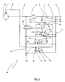
- Fig. 2 shows as a second embodiment of a compressed air treatment device, a compressed air treatment device 40, in which in the Regenerations effet.29 in place of the diaphragm 30 of the compressed air treatment device 1 in Fig. 1 a switchable by pressure actuation throttle valve 41 is arranged as a throttle element.
- the switchable throttle valve 41 as well as the throttle valves according to the embodiments according to Fig. 3 . 4 . 5 be arranged in front of or behind the check valve 31.
- the throttle valve 41 is designed as a 2/2-way valve, wherein a control input 42 is connected to the working port 24 of the regeneration valve 25.
- a valve spring 43 acts with its permanent restoring force against a pressure-actuated coupling input 44 of the throttle valve 41.
- the coupling input 44 is a second, actuated by pressure medium, control input of the throttle valve, which is connected to the working port 14 of the compressor valve 13. In the continuous position of the compressor valve 13 is therefore at the coupling input 44 of the system pressure from the supply line 11 at.
- the compressed air treatment device 40 corresponds to the Fig. 1 described structure.
- the regeneration valve 25 is supplied with its electrical control signal, so that the governor valve 19, the connection between the supply line 11 and the vent valve 32 is interrupted and the vent line 16 is locked.
- the compressor valve 13 is actuated, whereby the control switch 7 of the compressor 6 is actuated and the supply of compressed air is suppressed in the pressure line 2.
- the supply of the control signal for the regeneration valve 25 is interrupted so that the regeneration valve 25 reaches the first switching position shown.
- the control input 42 of the throttle valve 41 is connected to the vent line 16 and repealed the switching force of the control input 42.
- the coupling input 44 unfolds under the adjacent Control pressure of the supply line 11, a force which overcomes the valve spring 43 and the throttle valve 41 switches to the continuous position.
- Fig. 3 shows as a third embodiment of a compressed air treatment device, a compressed air treatment device 50, in which in the regeneration line 29 as a throttle element, a switchable throttle valve 51 is provided with two actuatable by pressure control inputs and two different passage cross-sections.
- a control input 52 is connected to the working port 24 of the regeneration valve 25.
- a pressure actuatable coupling input 53 is connected to the working port 14 of the compressor valve 13, which is used for the control of the compressed air supply.
- the coupling input 53 counteracts the control input 52 and the restoring force of a valve spring 54.
- the compressed air treatment device 50 corresponds to the already Fig. 1 described structure.
- the combination of the coupling input 53 of the throttle valve 51 with the working port 14 of the compressor valve 13 leads to a switching of the control pressure of the supply line 11 to the throttle valve 51, whereby the throttle valve 51 assumes its second switching position with a larger passage cross-section (for example, of 1.5 mm) ,
- the throttle valve 51 switches to the first switching position, in which a smaller passage cross-section (for example, 0.5 mm) is continuous. This achieves optimum relaxation of the dry compressed air from the system reservoirs at the Governor Switch Pressure reduced pressure level during backup operation.
- a smaller passage cross-section for example, 0.5 mm
- the switching off of the electrical control signals of both the compressor valve 13 and the regeneration valve 25 in the compressed air treatment device 50 causes a regeneration flow to set through the smaller passage cross section of the throttle valve 51.
- Fig. 4 shows as a fourth embodiment of a compressed air treatment device a compressed air circulation device 60, in which a designed as a 2/2-way valve switchable throttle valve 61 is provided for controlling the regeneration air flow.
- the throttle valve 61 has, in contrast to the other embodiments, a single pressure-actuatable control input 62, which is connected to the working port 24 of the regeneration valve 25.
- the switchable throttle valve 61 of the compressed-air circulation device 60 is not arranged in the regeneration line 29.
- a supply port 63 of the throttle valve 61 is connected to the working port 14 of the second solenoid valve 13 for the control of the compressed air supply and a working port 64 of the throttle valve 61 is connected via a connecting line 65 to the pressure line 2.
- the connecting line 65 in which a check valve 66 is arranged, opens parallel to the regeneration line 29 between drying unit 4 and check valve 5 in the pressure line 2.
- the regeneration line 29 is arranged with a non-return valve 31 and a diaphragm 30 in the Fig.1 described manner connected to the working port 20 of the Governor valve 19.
- the throttle valve 61 thus dominates the connecting line 65 and thus a second flow path for regeneration air.
- the aperture 30 in the regeneration line 29 is designed in this embodiment with a significantly smaller diameter than the switchable throttle valve 61, for example, 0.5 mm, so that the flow, when both throttle elements are opened in parallel, again in total allows optimal regeneration.
- the flow through the compressor valve 13 is in the embodiment after Fig. 4 significantly larger than in the embodiments according to Fig. 1 . Fig. 2 and Fig. 3 , and ensures safe control of the compressor 6 with simultaneous outflow of compressed air through the throttle valve 61.
- the control input 62 of the throttle valve 61 which is connected to the regeneration valve 25, counteracts the permanent restoring force of a valve spring 67, which holds the throttle valve 61 in the non-actuated state in the continuous switching position.
- the compressed air treatment device 60 corresponds to the already Fig. 1 described structure.
- the regeneration valve 25 is supplied by the electrical control unit with the control signal, the pressure of the supply line 11 acts on the control input 62 and switches the throttle valve 61 in the non-continuous second switching position.
- the regeneration valve 25 connects in the manner already described the vent line 16 to the second control input 23 of the governor valve 19, so that the governor valve 19 in turn connects the control pressure of the supply line 11 with its working port 20, the vent valve 32 switches and the vent line 16 is free.
- the throttle valve 61 is, when the regeneration valve 25 is not operated, in the first switching position in which it is continuous. Over the passage cross section thus the throttle valve 61 is continuous for a connection from the compressor valve 13 to the pressure line 2.
- the compressor valve 13 is supplied with an electrical control signal and thus the supply line 11 to the supply port 63 of the throttle valve 61 fluidly connected.
- the regeneration air then flows directly via the compressor valve 13 to the throttle valve 61, bypassing the governor valve 19 and finally passes through the connecting line 65 in the pressure line 2 to flow through the drying device 4 backward. In this way, regeneration air can be passed through both the regeneration line 29 and through the connecting line 65 to the drying device 4.
- both the regeneration line 29 and the connecting line 65 are thus released as a parallel flow path for the return flow into the pressure line 2, so that in total a large passage cross-section is given.
- the compressor valve 13 switches to the first switching position in which the throttle valve 61 is not supplied.
- a regeneration of the drying device 4 is taken over by the pressure-dependent control of the governor valve 19.
- the governor valve 19 releases a connection from the supply line 11 to the pressure line 2 when the governor switchover pressure in backup mode is exceeded.
- the compressed air supply from the compressor 6 is prevented by opening the vent valve 32.
- Fig. 5 shows as a fifth embodiment of a compressed air processing device, a compressed air processing device 70, in the similar to the arrangement according to Fig.
- a connecting line 73 dominates, which opens parallel to the regeneration line 29 in the flow direction 3 behind the drying device 4 in the pressure line 2.
- the supply connection 74 of the throttle valve 71 is fluidically connected to the supply line 11.
- the throttle valve 71 has analogous to the throttle valve 41 in Fig.2 two pressure-actuated control inputs, which act against each other.
- a control input 75 is similar to the embodiments according to Fig. 2 . 3 . 4 connected to the working port 24 of the regeneration valve 25.
- a coupling input 76 of the throttle valve 71 is fluidly connected to the working port 14 of the compressor valve 13.
- the control input 75 of the throttle valve 71 remains unactuated when the switch-off position of the regeneration valve 25 is unactuated.
- the compressor valve 13 connects in the regeneration operation, the supply line 11 with both the compressor control line 8 and the coupling input 76, which brings the throttle valve against the permanent restoring force of a valve spring 77 in the continuous switching position.
- the working port 14 of the compressor valve 13 is used in the embodiment according to Fig. 5 only the signal transmission to the throttle valve and the compressor circuit, so that no pressure losses caused by fluid flows.
- the control switch 7 of the compressor 6 can thus be switched safely.
- the compressor valve 13 structurally smaller dimensions and thereby costs can be saved.
- the switchable throttle valve which analogously to the embodiments of Fig. 4 and Fig. 5 a connection line dominated, be formed with different passage cross sections in the switching states.
Landscapes
- Engineering & Computer Science (AREA)
- Transportation (AREA)
- Mechanical Engineering (AREA)
- Valves And Accessory Devices For Braking Systems (AREA)
- Drying Of Gases (AREA)
- Fluid-Pressure Circuits (AREA)
Description
- Die Erfindung betrifft eine Druckluftaufbereitungseinrichtung mit einer Druckluft führenden Druckleitung, in der in Durchströmungsrichtung hintereinander eine Trocknungseinrichtung und ein Rückschlagventil angeordnet sind, wobei ein druckbetätigbares Zufuhrsteuerelement bei Anliegen des Steuerdrucks die Druckluftzufuhr zur Trocknungseinrichtung unterbindet, gemäß dem Oberbegriff des Patentanspruchs 1 sowie ein Kraftfahrzeug mit einer derartigen Druckluftaufbereitungseinrichtung.
- Kraftfahrzeuge weisen pneumatisch betriebene Einrichtungen auf, beispielsweise eine Druckluftbremsanlage, welche mit Druckluft versorgt werden müssen. Die Druckluft wird üblicherweise von einem Kompressor bereitgestellt, der Luft aus der Atmosphäre ansaugt und einen Druckluftstrom in die Druckleitung abgibt. Da die in der Luft enthaltene Luftfeuchtigkeit kondensiert und dadurch Korrosion verursachen kann, was die Lebensdauer von Bauelementen erheblich verkürzt, wird die Druckluft nach Verlassen des Verdichters getrocknet, bevor sie in das Leitungsnetz eingespeist wird. Zu diesem Zweck ist in der Druckleitung eine Trocknereinheit angeordnet. Es ist bekannt, Zufuhrsteuerelemente am Eingang der Druckleitung anzuordnen, um die Druckluftförderung durch den Kompressor ein- bzw. auszuschalten, um den Druck in der Druckleitung und damit im Verbrauchernetz zu steuern. Das Zufuhrsteuerelement kann ein mit Druckluft betätigter Steuereingang des Kompressors sein.
-
DE 196 38 837B4 undWO 2007/142008 A1 offenbart eine Druckmittelaufbereitungseinrichtung, welche zur Druckmittelversorgung einen Kompressor und ein dem Kompressor zugeordnetes 3/2-Wegeventil als Zufuhrsteuerelement vorsieht. Der kontinuierliche erzeugte Druckluftstrom kann über das Zufuhrsteuerventil entweder den nachgeschalteten Elementen der Druckaufbereitungseinrichtung oder Atmosphäre zugeführt werden. Das Zufuhrsteuerventil ist mittels seines Steuereingangs durch Druckluft betätigbar. Diesem Zufuhrsteuerventil sind bei der bekannten Einrichtung ein Lufttrockner sowie ein Rückschlagventil nachgeschaltet. An das Rückschlagventil ist dabei ein Mehrkreisschutzventil angeschlossen, an welches die einzelnen Druckmittelkreise der Druckmittelanlage anschließbar sind. An den Steuereingang des Zufuhrsteuerventils ist eine Druckregeleinrichtung angeschlossen, welche eine hinter dem Rückschlagventil aus der Druckleitung abzweigende Vorratsleitung mit dem Steuereingang des Zufuhrsteuerventils verbinden kann, um die Druckluftzufuhr zur Druckleitung zu unterbinden. Die Druckregeleinrichtung bei der bekannten Anordnung besteht im Wesentlichen aus einem druckbetätigbaren Governor-Ventil und einem elektrisch betätigbaren Steuerventil. Ein erster Steuereingang des Governor-Ventils ist an die Vorratsleitung angeschlossen und arbeitet gegen eine permanente Rückstellkraft einer Ventilfeder. Der Ausgang des Governor-Ventils ist an das Zufuhrsteuerventil angeschlossen. Das elektrisch betätigbare Steuerventil ist mit seinem Einlass ebenfalls an die Vorratsleitung angeschlossen und ist mit seinem Auslass mit einem zweiten Steuereingang des Governor-Ventils verbunden, wobei der zweite Steuereingang dem ersten Steuereingang des Governor-Ventils entgegenwirkt. Das elektrisch betätigbare Steuerventil bzw. dessen Steuereingang ist über eine elektrische Leitung mit einem elektronischen Steuergerät verbunden. Das Steuergerät erzeugt in Abhängigkeit einer Druckmessung in der Vorratsleitung und damit der Druckleitung ein Steuersignal zur Steuerung des elektrischen Ventils. - Das elektrisch betätigbare Ventil wirkt als Vorsteuerung des Governor-Ventils und verursacht eine Umschaltung des Governor-Ventils zur Einwirkung auf die Druckluftzufuhr in die Druckleitung. Sobald das elektrisch betätigte Ventil den zweiten Steuereingang des Governor-Ventils mit der Vorratsleitung verbindet, heben sich die Steuerkräfte der beiden druckgesteuerten Steuereingänge des Governor-Ventils gegenseitig auf und die Rückstellkraft seiner Ventilfeder schaltet das Governor-Ventil in die durchgängige Stellung. In dieser Schaltstellung ist die Vorratsleitung mit dem Zufuhrsteuerventil am Kompressor verbunden, so dass die Druckluftzufuhr in die Druckleitung getrennt und der Druckluftstrom des Kompressors der Atmosphäre zugeführt wird.
- Obwohl im Normalbetrieb die Drucksteuerung bei der bekannten Einrichtung über das elektrisch betätigbare Ventil erfolgt, kann die bekannte Einrichtung bei Stromausfall und damit Ausfall des Steuerventils einen Notmodus aufrechterhalten, wobei die Zufuhrsteuerung allein druckabhängig erfolgt. Bei Stromausfall schaltet sich das elektrisch betätigbare Ventil in die nicht durchgängige Schaltstellung, so dass der zweite Steuereingang des Governor-Ventils ebenfalls nicht betätigt wird. Das Governor-Ventil verbindet dann die Vorratsleitung mit dem Zufuhrsteuerventil, wenn der Druck in der Druckleitung und damit der Vorratsleitung über den ersten Steuereingang des Governor-Ventils die entgegenstehende Federkraft überwindet. Durch die Einstellung der Rückstellkraft der Ventilfeder des Governor-Ventils wird der vorgesehene Governor-Umschaltdruck bestimmt, der vom Governor über entsprechende Schaltung der Druckluftzufuhr gehalten wird.
- Die bekannte Druckluftaufbereitungseinrichtung kann zwar bei Ausfall der elektrischen Steuerenergie eine druckabhängige Steuerung des Arbeitsdrucks über das Governor-Ventil in einem Notmodus aufrechterhalten. Eine unbegrenzte Weiterfahrt des Kraftfahrzeugs im Notmodus ist mit der bekannten Druckluftaufbereitungseinrichtung nicht möglich, da nach Ausfall der elektrischen Steuerenergie sehr rasch die Qualität der Druckluftaufbereitung abnimmt.
- Der vorliegenden Erfindung liegt die Aufgabe zugrunde, eine Druckluftaufbereitungseinrichtung der gattungsgemäßen Art derart weiterzubilden, dass eine unbegrenzte Weiterfahrt des Kraftfahrzeugs bei Ausfall der elektrischen Steuerung der Ventile der Druckluftaufbereitungseinrichtung möglich ist.
- Diese Aufgabe wird erfindungsgemäß durch eine Druckluftaufbereitungseinrichtung mit den Merkmalen des Patentanspruchs 1 und ein Kraftfahrzeug mit den Merkmalen des Patentanspruchs 10 gelöst.
- Der Erfindung liegt die Erkenntnis zugrunde, dass die zur Luftaufbereitung erforderliche Trocknungseinrichtung der durchströmenden Druckluft durch Kondensation und Adsorption die Feuchtigkeit entzieht und das Adsorptionsmittel in der Trocknungseinrichtung eine begrenzte Wasseraufnahmekapazität hat. Die Trocknungseinrichtung muss deshalb in bestimmten Abständen regeneriert werden. Schaltet die bekannte Einrichtung zur Steuerung der Druckluftaufbereitungseinrichtung bei Ausfall der elektrischen Steuerenergie in den Notmodus, so wird zwar zunächst ein Fahrbetrieb des Kraftfahrzeuges aufrechterhalten. Die Wasseraufnahmekapazität der Trocknungseinrichtung ist jedoch rasch erschöpft, so dass die Funktion der Druckluftaufbereitungseinrichtung nicht mehr gewährleistet ist.
- Mit der erfindungsgemäßen Druckluftaufbereitung wird auch bei Ausfall der elektrischen Energieversorgung der Steuerung der Ventile der Druckluftaufbereitung regelmäßig eine Regeneration der Trocknungseinrichtung durchgeführt, da die Regeneration durch das bei Ausfall der elektrischen Energieversorgung weiterhin aktive Governor-Ventil gesteuert wird. Ein Kraftfahrzeug, das mit der erfindungsgemäßen Druckluftaufbereitungseinrichtung ausgerüstet ist, kann daher nahezu unbegrenzt seine Fahrt fortführen. Das Governor-Ventil übernimmt im stromlosen Betrieb die Steuerung sowohl der Druckluftaufbereitung als auch der Regeneration der Trocknungseinrichtung.
- Unter Governor-Ventil ist ein druckbetätigbares Ventil zu verstehen, welches auf die Steuerung der Druckluftzufuhr wirkt und auf dessen Steuereingang der Systemdruck wirkt, den die Druckluftaufbereitungseinrichtung für die angeschlossenen pneumatischen Kreise erzeugt. Eine Vorsteuerung des Governor-Ventils ist gegeben, wenn ein zweiter Steuereingang des Governor-Ventils, der dem ersten Steuereingang entgegen wirkt, abhängig von dem vorsteuernden Magnetventil mit dem Systemdruck beaufschlagbar ist.
- Das Governor-Ventil, welches bei elektrischem Betrieb von einem elektrisch betätigbaren Magnetventil vorgesteuert ist, steuert während des elektrischen Betriebs die Druckluftaufbereitung auf einem hohen Druckniveau. Bei Ausfall der elektrischen Energie und einem dadurch bedingten Ausfall der Vorsteuerung spricht das Governor-Ventil bei Anliegen eines Drucks an, welcher die mechanische Rückstellkraft des Governor-Ventils überwindet, beispielsweise eine Federkraft. Das zweite Druckniveau, bei dem das Governor-Ventil bei Ausfall der elektrischen Versorgung anspricht, ist niedriger als das hohe Druckniveau bei elektrisch betätigter Vorsteuerung, so dass bei Ausfall der elektrischen Versorgung ein weiterer Betrieb der Druckluftaufbereitungseinrichtung auf niedrigerem Druckniveau erfolgt.
- In einer vorteilhaften Ausführungsform ist ein Versorgungsanschluss des Governor-Ventils mit einer Vorratsleitung verbunden, welcher aus einer an die Druckleitung anschließenden Systemdruckleitung abzweigt. Die Druckleitung und die Systemdruckleitung sind durch ein Rückschlagventil getrennt. Ein Arbeitsanschluss des Governor-Ventils ist an ein druckbetätigbares Zufuhrsteuerelement angeschlossen, welches bei Anliegen des Steuerdrucks die Druckluftzufuhr zur Trocknungseinrichtung unterbindet und eine Regeneration ermöglicht. Als Arbeitsanschluss ist dabei derjenige Anschluss eines Ventils zu verstehen, welcher abhängig von der Ventilstellung mit dem Versorgungsanschluss des Ventils verbindbar ist, wobei der Versorgungsanschluss derjenige Anschluss des Ventils ist, der ständig druckbeaufschlagt ist und der Druckluftversorgung dient. Sofern ein Ventil über einen Entlüftungsanschluss verfügt, so ist dies ein solcher Anschluss, der alternativ zum Versorgungsanschluss mit dem Arbeitsanschluss verbindbar ist. Zur Durchführung der Regeneration werden der Arbeitsanschluss und der Versorgungsanschluss des Governor-Ventils von dem ersten Steuereingang des Governor-Ventils, der an die Vorratsleitung angeschlossen ist und gegen eine permanente Rückstellkraft arbeitet, miteinander verbunden.
- Als Mittel zur Durchführung der Regeneration sind eine an das Governor-Ventil angeschlossene Regenerationsleitung und eine Entlüftungsleitung vorgesehen. Die Regenerationsleitung zur Zuführung von Regenerationsluft für die Trocknungseinrichtung mündet in Durchströmungsrichtung der Druckleitung hinter der Trocknungseinrichtung in die Druckleitung ein. Die Entlüftungsleitung zweigt in Durchströmungsrichtung vor der Trocknungseinrichtung aus der Druckleitung ab und wird während der Regeneration frei gegeben.
- Durch die Regenerationsleitung, die an das Governor-Ventil angeschlossen ist; kann in dem Moment, wo das Governor-Ventil die durchgängige Stellung einnimmt, Druckluft durch die Regenerationsleitung zur Trocknungseinrichtung geleitet werden.
- In der zwischen Vorratsleitung und Regenerationsleitung durchgängigen Schaltstellung des Governor-Ventils ist eine Durchströmung der Trocknungseinrichtung in entgegengesetzter Strömungsrichtung möglich, um das Trocknungsmittel zu regenerieren. Der Regenerationsluftstrom nimmt die Feuchtigkeit aus der Trocknungseinrichtung mit. Er kann durch die Entlüftungsleitung abgeführt werden, welche in Durchströmungsrichtung vor der Trocknungseinrichtung aus der Druckleitung abzweigt. Die Regenerationsleitung ist dabei zweckmäßig zwischen der Trocknungseinrichtung und dem Rückschlagventil an die Druckleitung angeknüpft, so dass zur Regeneration des Trockners Druckluft aus den Systembehältern unter Umgehung des Rückschlagventils zurück strömen kann.
- Mit der erfindungsgemäßen Anordnung einer Regenerationsleitung zwischen dem Governor-Ventil und der Druckleitung kann mit einfachen Mitteln eine Regeneration der Trocknungseinrichtung mit Druckluft aus den Systembehältern erfolgen und auf einem separaten Regenerationsbehälter für die Trocknungseinrichtung verzichtet werden. Die Regenerationsluft wird einer Vorratsleitung entnommen, die hinter dem Rückschlagventil der Druckleitung von der Systemdruckleitung abzweigt. Die Vorratsleitung übernimmt somit sowohl die Funktion der Zuführung von Regenerationsluft als auch der druckabhängigen Steuerung des Governor-Ventils im stromlosen Betrieb.
- In einer bevorzugten Ausführungsform unterbindet das Governor-Ventil während des Regenerationsbetriebes in seiner durchgängigen Stellung die Druckluftzufuhr zur Trocknungseinrichtung, indem es die Entlüftungsleitung frei gibt. Hierzu ist in der Entlüftungsleitung ein druckbetätigbares Entlüftungsventil angeordnet, dessen Steuereingang mit der Regenerationsleitung fluidisch verbunden ist. Dadurch wird die Entlüftungsleitung nur nach Einleitung der Regeneration durch Verbindung der Regenerationsleitung mit der Vorratsleitung geöffnet.
- Im mechanischen Betrieb, das heißt ohne elektrische Versorgung der Ventile, funktioniert das Entlüftungsventil auch als Zufuhrsteuerelement für die Druckluftzufuhr in der Druckleitung. Bei geöffneter Entlüftungsleitung wird der eingespeiste Druckluftstrom eines Kompressors durch die Entlüftungsleitung abgeleitet. Um sowohl Zufuhrsteuerung als auch Regeneration im stromlosen Betrieb zu ermöglichen, ist der Öffnungsdruck des Entlüftungsventils mit dem Ansprechdruck des Governor-Ventils abgestimmt, so dass bei Belüften der Vorratsleitung durch das Governor-Ventil das Entlüftungsventil sicher öffnet.
- Eine präzise Steuerung der Regeneration ist in einer vorteilhaften Ausführungsform der elektrischen Steuerung der Druckluftaufbereitungseinrichtung möglich, wenn das elektrisch betätigbare Magnetventil, welches das Governor-Ventil vorsteuert, als den Luftstrom in der Regenerationsleitung steuerndes Regenerationsventil angeordnet ist. Ein Versorgungsanschluss des Regenerationsventils ist dabei an die Vorratsleitung angeschlossen und durch Schalten eines elektrischen Steuereingangs mit einem Arbeitsanschluss verbindbar, welcher an den zweiten Steuereingang des Governor-Ventils angeschlossen ist. Der zweite Steuereingang wirkt dem ersten Steuereingang des Governor-Ventils entgegen. Das Governor-Ventil wird dadurch von dem Regenerationsventil vorgesteuert, so dass die Durchführung der Regeneration bei entsprechender Schaltung des Regenerationsventils erfolgt und bei Ausfall der elektrischen Energieversorgung das Governor-Ventil die Steuerung übernimmt.
- Dabei ist ein weiteres elektrisch betätigbares Magnetventil als die Druckluftzufuhr steuerndes Kompressorventil angeordnet, wodurch der Regenerationsbetrieb der Druckluftaufbereitungseinrichtung bei elektrischer Steuerung von der Drucksteuerung entkoppelt wird. Das Kompressorventil ist zu diesem Zweck zwischen der Vorratsleitung und einem Steuereingang eines Zufuhrsteuerelements angeordnet. Im Normalbetrieb der Druckluftaufbereitungseinrichtung kann somit die Regeneration in steuerbaren Zeitabständen durchgeführt werden, indem das Regenerationsventil geschaltet wird. Die Drucksteuerung erfolgt davon losgelöst, indem das Kompressorventil in die durchgängige Stellung durch Zuführung eines elektrischen Signals geschaltet wird und dadurch ein Arbeitsanschluss des Kompressorventils, der mit dem Zufuhrsteuerelement verbunden ist, mit einem Versorgungsanschluss verbunden wird.
- Das dem Kompressorventil zugeordnete Zufuhrsteuerelement ist in der Druckleitung in Durchströmungsrichtung vor der Trocknungseinrichtung angeordnet und beherrscht die Zuführung der Druckluft in die Druckleitung. Vorteilhaft bildet ein druckbetätigbarer Steuerschalter des Kompressors das Zufuhrsteuerelement, so dass der Kompressor direkt gesteuert wird. Alternativ kann auch ein druckbetätigbarer Steuerauslass des Kompressors als Zufuhrsteuerelement vorgesehen sein, welcher bei Anliegen des pneumatischen Steuersignals den Kompressorluftstrom in die Atmosphäre leitet. In einer weiteren alternativen Ausführungsform bildet ein separates 3/2-Wege-Ventil in der Druckleitung das Zufuhrsteuerelement bei elektrischer Steuerung der Druckluftaufbereitungseinrichtung.
- Im Normalbetrieb hält das Entlüftungsventil die Entlüftungsleitung geschlossen, so dass Druckverluste in der Druckleitung vermieden sind. Sollte die elektrische Energieversorgung der Druckluftsaufbereitungseinrichtung und damit die Schaltung der Druckluftzufuhr über das Kompressorventil ausfallen, bildet das Entlüftungsventil das Zufuhrsteuerelement der Druckluftaufbereitungseinrichtung. Im stromlosen Backup-Betrieb öffnet das Governor-Ventil bei Erreichen des vorgegebenen Abschaltdrucks in der Vorratsleitung das Entlüftungsventil, so dass der Druckluftstrom des Kompressors durch die Entlüftungsleitung abgeführt wird. Da das Governor-Ventil erst nach einer gewissen Druckhysterese schließt, bleibt das Entlüftungsventil geöffnet, bis der Systemdruck unter einen Rückschaltdruck fällt, der durch den Abschaltdruck abzüglich der Hysterese bestimmt ist. Das Entlüftungsventil kann ein einfach gestaltetes 2/2-Wege-Ventil sein, dessen Steuereingang unter dem Druck der Regenerationsleitung gegen eine Federkraft die Sperrung der Entlüftungsleitung aufhebt und die Entlüftungsleitung auf durchgängig schaltet. Gleichzeitig wird im stromlosen Backup-Betrieb bei Erreichen des Abschaltdrucks die Regeneration des Trocknungsmittels durch rückströmende Luft eingeleitet. Wieder wird diese Regeneration so lange durchgeführt, bis das Governor-Ventil wieder schließt, also bis der Systemdruck unter den Abschaltdruck abzüglich Hysterese fällt.
- Ist in der Regenerationsleitung ein Rückschlagventil angeordnet, so werden die Drucksteuerventile sicher vor dem Druck der Druckleitung geschützt und eine unerwünschte Abströmung aus der Druckleitung vermieden.
- Ist in der Regenerationsleitung ein Drosselelement angeordnet, so wird die aus den Systembehältern bei der Regeneration zurückströmende Druckluft vor der Zuführung zum Trockner auf das geeignete Druckniveau entspannt. Das Drosselelement kann dabei als Blende oder in vorteilhafter Weiterbildung als schaltbares Drosselventil ausgebildet sein.
- Mit der erfindungsgemäßen Anordnung kann eine Baugruppe als Grundlage für elektrisch und mechanisch gesteuerte Druckluftaufbereitungseinrichtungen zur Verfügung gestellt werden. An die im Wesentlichen gleiche Grund-Baugruppe werden je nach Einsatz weitere Bauteile zugefügt und gegebenenfalls unterschiedlich angeschlossen
- Vorteilhaft ist das Regenerationsventil als 3/2-Wege-Ventil ausgebildet, dessen dritter Anschluss als Entlüftung wirkt, so dass mit einfachen Mitteln nach einer Regeneration der Trocknungseinrichtung der zweite Steuereingang des Governor-Ventils entlüftet wird. Das 3/2-Wege-Regenerationsventil verbindet in der unbetätigten Schaltstellung den Steuereingang des Governor-Ventils mit der Entlüftungsleitung, so dass bei einem Anlegen des Steuersignals am Regenerationsventil und Überführung des Regenerationsventils in die zweite Schaltstellung sofort der Steuerdruck an den Steuereingang des Governor-Ventils gelegt wird.
- In einer vorteilhaften Ausführungsform der Erfindung werden beide elektrisch betätigbare Magnetventile, also Regenerationsventil und Kompressorventil, von einer elektronischen Steuereinheit angesteuert, so dass eine präzise Steuerung des Arbeitsdrucks im Druckluftsystems des Kraftfahrzeugs und der turnusmäßigen Regeneration der Trocknungseinrichtung nach vorgegebenen Kennfelddaten erfolgen kann. Der Steuereinheit werden dabei geeignete Messparameter eingegeben und die vorher ermittelten optimalen Steuerwerte vorgegeben, so dass eine optimale Ansteuerung des Regenerationsventils bzw. des Kompressorventils für die Steuerung der Druckluftzufuhr erfolgen kann. Sollte die elektrische Steuerenergie ausfallen, so fällt die Druckluftaufbereitungseinrichtung in den Notbetrieb (Backup), wobei erfindungsgemäß das Governor-Ventil die Drucksteuerung und die Steuerung der Trocknerregeneration übernimmt.
- Das Regenerationsventil kann mit einem Öffnungsdurchmesser von 1 mm ausgeführt werden, um die pneumatische Betätigung des Governor-Ventils sicherzustellen. Für das Kompressorventil wird ein Öffnungsdurchmesser von 1,6 mm als vorteilhaft gesehen, um eine sichere Schaltung des Zufuhrsteuerelements und des in der Druckleitung bzw. des steuerbaren Druckauslasses des Kompressors zu gewährleisten. Das Governor-Ventil wird vorteilhaft mit einem größeren Öffnungsdurchmesser als die elektrisch betätigbaren Magnetventile ausgestattet, um einen hinreichenden Durchfluss des Regenerationsluftstroms zu gewährleisten. Für den Öffnungsdurchmesser des Governor-Ventils wird ein Wert von etwa 2 mm als vorteilhaft gesehen.
- In einer vorteilhaften Ausführungsform der Erfindung wird die Strömung der Regenerationsluft mittels eines durch Druckbetätigung schaltbaren Drosselventils bestimmt, dessen Steuereingang mit dem Regenerationsventil verbunden ist. Dadurch wirkt das Regenerationsventil so lange, wie es in seinem betätigten Zustand das Governor-Ventil beaufschlagt und vorsteuert, auch auf das Drosselventil und kann beispielsweise den für Regenerationsbetrieb vorgesehenen Durchtrittsquerschnitt des Drosselventils ausschalten. Das schaltbare Drosselventil ermöglicht eine schaltbare Veränderung des Durchtritts der Regenerationsleitung, so dass eine Vielzahl von Anknüpfungsmöglichkeiten für die Verfeinerung und Variation der Drucksteuerung und Regenerationssteuerung im Normalbetrieb mit elektrischen Steuersignalen gegeben ist.
- Vorteilhaft weist das schaltbare Drosselventil einen durch Druckbetätigung schaltbaren Koppelungseingang auf, welcher mit dem Arbeitsanschluss des Kompressorventils verbunden ist und entgegen der Betätigung des Drosselventils durch den Steuereingang und entgegen der Rückstellkraft einer Ventilfeder -wirkt. Dadurch wird der Regenerationsbetrieb bei einer elektrisch gesteuerten Luftaufbereitungseinrichtung direkt an die Abschaltung der Druckluftzufuhr in die Druckleitung geknüpft. Wird nach einer Regeneration das Regenerationsventil wieder mit einem elektrischen Schaltsignal beaufschlagt, so heben sich die Druckkräfte der entgegen wirkenden Steuereingänge des Drosselventils auf und die Ventilfeder schaltet das Drosselventil in die zweite Schaltstellung, welche für die übrigen Betriebsmodi außerhalb des Regenerationsbetriebs vorgesehen ist.
- Vorteilhaft weist das schaltbare Drosselventil zwei Schaltzustände mit unterschiedlichen Durchtrittsquerschnitten auf, so dass ein optimaler Durchtrittsquerschnitt für den Normalbetrieb der Einrichtung und Steuerung der Regeneration über das Regenerationsventil gewählt werden kann. Für die zweite Schaltstellung des Drosselventils, in die das Drosselventil fällt, wenn der mit dem Kompressorventil verbundene zweite Steuereingang nicht beaufschlagt wird, wird der für den Backup-Betrieb bei Steuerung über das Governor-Ventil optimale Durchtrittsquerschnitt vorgesehen. Zweckmäßig ist dabei der Durchtrittsquerschnitt im unbetätigten Zustand des Drosselventils, also der für die Regeneration im Backup-Betrieb vorgesehene Durchtrittsquerschnitt, kleiner als der Durchtrittsquerschnitt im betätigten Zustand für den elektrischen Steuerbetrieb. Über die Betätigung des Kompressorventils im Regenerationsbetrieb wird auch das Drosselventil betätigt und der größere Durchtrittsquerschnitt eingestellt. Im Backup-Betrieb hält das Governor-Ventil den Systemdruck im Bereich zwischen Abschaltdruck und dem Rückschaltdruck, der sich aus dem Abschaltdruck abzüglich Hystereseergibt. Durch die gleichzeitig stattfindende Regeneration entweicht in diesem Modus permanent Druckluft aus dem System. Deshalb ist ein kleinerer Querschnitt vorteilhaft, um zu schnellen Abfall des Systemdrucks zu vermeiden und somit Energie, die für das Wiederauffüllen bis zum Abschaltdruck notwendig wäre, zu sparen. Für den Normalbetrieb hat sich ein Durchtrittsquerschnitt von etwa 1,5 mm als zweckmäßig erwiesen. Für den Durchtrittsquerschnitt im Backup-Betrieb wird ein kleinerer Durchtrittsquerschnitt von etwa 0,5 mm als ausreichend gesehen.
- Das schaltbare Drosselventil ist in einer weiteren vorteilhaften Ausführungsform der Erfindung alternativ zur Anordnung in der Regenerationsleitung in einer parallel zur Regenerationsleitung und in Durchströmungsrichtung hinter der Trocknungseinrichtung in die Druckleitung einmündenden Verbindungsleitung angeordnet. Die Verbindungsleitung ist mittels des Kompressorventils für die Druckluftsteuerung mit der Vorratsleitung verbindbar. Auf diese Weise steht im Regenerationsbetrieb der elektrisch gesteuerten Druckluftaufbereitungseinrichtung ein großer Durchtrittsquerschnitt für einen kräftigen Regenerationsluftstrom zur Verfügung, da trockene Druckluft aus den Systembehältern parallel durch die Regenerationsleitung und die gleichfalls durchgängige Verbindungsleitung fließen kann. Um eine fluidische Verbindung zwischen der Vorratsleitung und der Verbindungsleitung schalten zu können, ist der Arbeitsanschluss des Kompressorventils entweder mit dem Versorgungsanschluss des Drosselventils oder einem druckabhängigen Koppelungseingang des Drosselventils verbunden, wobei in der zweiten Variante der Versorgungsanschluss des Drosselventils mit der Vorratsleitung verbunden ist.
- Im Backup-Betrieb bei Ausfall der elektrischen Energieversorgung der Ventile übernimmt das Governor-Ventil wie bereits beschrieben die druckabhängige Schaltung der Regeneration.
- Im Backup-Betrieb ohne elektrische Steuerung strömt die Druckluft zur Regeneration durch die Regenerationsleitung unter Umgehung des Drosselventils.
- Weiterer Vorteil der Anordnung des Drosselventils in einer parallelen Verbindungsleitung ist die Möglichkeit eines optimalen Abblasbetriebes ("Cold dump") mit reduziertem Durchsatz gegenüber dem elektrisch gesteuerten Regenerationsbetrieb. Dabei wird weder dem Kompressorventil für die Drucksteuerung noch dem Regenerationsventil ein elektrisches Steuersignal zugeführt, so dass das Governor-Ventil unter dem Druck der Vorratsleitung den Strömungsweg durch die Entlüftungsleitung freigibt. Der Abblasbetrieb wird insbesondere bei kalten Umgebungstemperaturen von der elektrischen Steuereinheit zwischenzeitlich eingestellt, um einer Vereisung der Druckleitung und der darin angeordneten Aggregate sowie dem Entlüftungsventil mittels warmer Luft vom Kompressor entgegen zu wirken. Im Abblasbetrieb erfolgt der Rückstrom nur über die Regenerationsleitung. Es stellt sich daher ein geringerer Massenstrom durch den Trockner ein, so dass die Durchströmung der Trocknungseinrichtung in umgekehrter Richtung begrenzt wird.
- Durch die Anbindung der Schaltung des Drosselventils an die Schaltstellung des Kompressorventils wird die Regeneration im Normalbetrieb bei elektrischer Steuerung direkt an die Abschaltung der Druckluftzufuhr durch den Kompressor gekoppelt. Bei einer Wiederaufnahme der Druckluftzufuhr durch Umschalten des Kompressorventils wird durch das gleiche Ventilglied, nämlich das des Kompressorventils, ohne jeglichen Verzug der Strömungsweg in umgekehrter Richtung gesperrt.
- Ein direkter Durchfluss der Regenerationsluft zum Trockner ohne Durchströmung anderer Ventile als dem Drosselventil ist gemäß einer weiteren Ausführungsform der Erfindung gegeben, wenn der Versorgungsanschluss des Drosselventils in der Verbindungsleitung mit der Vorratsleitung verbunden ist. Ein zweiter Steuereingang des Drosselventils, welcher dem ersten, mit dem Regenerationsventil verbundenen, Steuereingang entgegen wirkt, ist dabei mit dem Arbeitsanschluss des Kompressorventils verbunden. Bei durchgängiger Stellung des Kompressorventils wirkt demnach der Druck am Versorgungsanschluss des Kompressorventils, also der Systemdruck, auf den Koppelungseingang des Drosselventils. Bei durchgängiger Stellung des Drosselventils strömt Druckluft direkt aus der Vorratsleitung zum Drosselventil und anschließend durch die Verbindungsleitung in die Druckleitung, so dass die elektrisch betätigbaren Magnetventile nicht durchströmt und weniger belastet werden.
- Vorteilhaft an der Versorgung der Verbindungsleitung direkt aus der Vorratsleitung ist auch, dass der Arbeitsanschluss des Kompressorventils nur zur Signalübertragung dient und daher das Zufuhrsteuerelement des Kompressors sicherer geschaltet werden kann. Auch kann das Kompressorventil baulich kleiner dimensioniert und dadurch Kosten eingespart werden.
- Das Drosselelement in der Regenerationsleitung kann eine Blende mit einem kleineren Durchtrittsquerschnitt als der Querschnitt des Drosselventils sein, so dass im Abblasbetrieb der gewünschte reduzierte Luftstrom in entgegen gesetzter Durchströmungsrichtung entsteht, welcher im Backup-Betrieb noch für eine Regeneration ausreicht.
- Vorteilhaft kann ein schaltbares Drosselventil in der Verbindungsleitung mit zwei Schaltzustände mit unterschiedlichen Durchtrittsquerschnitten ausgebildet sein, wodurch die Entspannung der trockenen Druckluft aus den Systembehältern bei dem auf Governor-Umschaltdruck reduzierten Druckniveau im Backup-Betrieb durch Einstellung eines optimierten Durchtrittsquerschnitt gefördert wird. Weitere Ausführungsformen der Erfindung ergeben sich aus den Unteransprüchen und den Ausführungsbeispielen, die nachstehend anhand der Zeichnung näher erläutert sind. Es zeigen:
- Fig.1
- eine fluidtechnisches Schaltbild einer Druckluftaufbereitungseinrichtung nach einem ersten Ausführungsbeispiel,
- Fig.2
- eine fluidtechnisches Schaltbild einer Druckluftaufbereitungseinrichtung nach einem zweiten Ausführungsbeispiel,
- Fig.3
- eine fluidtechnisches Schaltbild einer Druckluftaufbereitungseinrichtung nach einem dritten Ausführungsbeispiel,
- Fig.4
- eine fluidtechnisches Schaltbild einer Druckluftaufbereitungseinrichtung nach einem vierten Ausführungsbeispiel,
- Fig.5
- eine fluidtechnisches Schaltbild einer Druckluftaufbereitungseinrichtung nach einem fünften Ausführungsbeispiel.
- Für jeweils gleiche Bauteile sind in den Zeichnungsfiguren die jeweils gleichen Bezugszeichen verwendet.
-
Fig. 1 zeigt eine elektrisch gesteuerte Druckluftaufbereitungseinrichtung 1 mit einer Druckleitung 2, in der ebenso wie bei den Druckluftaufbereitungseinrichtungen nach denFig.2 ,3 ,4 ,5 in Durchströmungsrichtung 3 hintereinander eine Trocknungseinrichtung 4 und ein Rückschlagventil 5 angeordnet sind. An das Rückschlagventil 5 ist ein hier nicht dargestelltes Sicherheitsventil oder Mehrkreisschutzventil angeschlossen, an die einzelne Druckmittelkreise wie z.B. die Druckmittelkreise einer Druckluftbremsanlage eines Kraftfahrzeuges anschließbar sind. Diese Druckmittelkreise sind in den Zeichnungsfiguren nicht dargestellt. - Im Folgenden wird der gemeinsame Aufbau sämtlicher Ausführungsbeispiele am Beispiel von
Fig. 1 beschrieben. Auf Besonderheiten einzelner Ausführungsbeispiele ist an der jeweiligen Stelle der Figurenbeschreibung hingewiesen. - Die Druckluftzufuhr erfolgt in allen Ausführungsbeispielen über einen Kompressor 6. Ein druckbetätigbarer Steuerschalter 7 des Kompressors 6 bildet ein Zufuhrsteuerelement der Druckluftaufbereitungseinrichtung, so dass die Druckluftzufuhr in die Druckleitung 2 direkt geschaltet wird. Alternativ kann als dem Kompressor 6 zugeordnetes druckbetätigbares Zufuhrsteuerelement ein druckbetätigbarer Steuerauslass des Kompressors vorgesehen sein, der bei Betätigung den Kompressorstrom ableitet oder aber ein separates 3/2-Wege-Ventil in der Druckleitung. Der Kompressor 6 saugt Luft aus der Atmosphäre an und gibt einen Druckluftstrom in die Druckleitung 2 ab. Der Steuerschalter 7 ist über eine Kompressorsteuerleitung 8 durch Druckluft betätigbar. Sobald am Steuerschalter 7 über die Kompressorsteuerleitung 8 der Steuerdruck anliegt, wird die Drucklufteinspeisung unterbunden.
- Hinter dem Rückschlagventil 5 schließt sich an die Druckleitung 2 eine Systemdruckleitung 9 an, in der der für die Vorratsbehälter vorgesehene Systemdruck herrscht. Um den Steuerdruck an den Steuerschalter 7 anzulegen ist die Kompressorsteuerleitung 8 fluidisch mit einer Vorratsleitung 11 verbindbar, welche hinter dem Rückschlagventil 5 aus der Systemdruckleitung 9 abzweigt. Das Rückschlagventil 5 koppelt die vom Kompressor kommende Druckleitung 2 von den Vorratsbehältern (in der Darstellung nicht dargestellt) ab, so dass in der Vorratsleitung 11 das Systemdruckniveau aus den Vorratsbehältern erhalten bleibt, auch wenn die Druckleitung 2 in Strömungsrichtung 3 vor dem Rückschlagventil 5 während der Regeneration drucklos ist.
- Die Vorratsleitung 11 ist an den Versorgungsanschluss 12 eines elektrisch betätigbaren Kompressorventils 13 angeschlossen. Bei dem Kompressorventil 13 handelt es sich um ein zweites Magnetventil, welches zusätzlich zu einem elektrisch betätigbaren Regenerationsventil angeordnet ist, welches die Regeneration der Trocknungseinrichtung steuert und unten noch näher beschrieben ist. Zur Steuerung der Druckluftzufuhr ist an einen Arbeitsanschluss 14 des Kompressorventils 13 das Zufuhrsteuerelement angeschlossen, also in den gezeigten Ausführungsbeispielen der Steuerschalter 7 über die Kompressorsteuerleitung 8. Das Kompressorventil 13 ist in allen Ausführungsbeispielen als 3/2-Wege-Ventil ausgebildet, wobei der Arbeitsanschluss 14 entweder in einer ersten Schaltstellung des Kompressorventils 13 mit dem Versorgungsanschluss 12, das heißt mit der Vorratsleitung 11, oder in einer zweiten Schaltstellung mit einem dritten Anschluss, nämlich einem Entlüftungsanschluss15, verbunden ist. An den Entlüftungsanschluss 15 ist eine Entlüftungsleitung 16 angeschlossen. Die Entlüftungsleitung 16 dient in den Ausführungsbeispielen der Entlüftung weiterer, noch zu beschreibender Ventile der jeweiligen Druckluftaufbereitungseinrichtungen. Alternativ kann auch für jedes Ventil eine separate Entlüftung vorgesehen sein.
- Ein elektrisch betätigbarer Steuereingang 17 des Kompressorventils 13 ist über eine elektrische Leitung mit einem nicht dargestellten elektronischen Steuergerät verbunden. Dem Steuergerät werden durch geeignete Drucksensoren laufend ermittelte Informationen über den Systemdruck in dem in Durchströmungsrichtung 3 hinter dem Rückschlagventil 5 liegenden Abschnitt der Druckleitung 2 (also in oder hinter der Systemdruckleitung 9) eingegeben. Der Systemdruck wird, beispielsweise am Abzweig der Vorratsleitung 11 oder in der Vorratsleitung 11 erfasst. In Abhängigkeit von diesen Informationen und ggf. weiterer Eingangssignale erzeugt das Steuergerät elektrische Steuersignale zur Steuerung des Kompressorventils 13.
- Mit der Vorratsleitung 11 ist außerdem ein erster Steuereingang 18 eines druckbetätigbaren Governor-Ventils 19 verbunden. Das Governor-Ventil 19 ist als 3/2-Wege-Ventil ausgestaltet, wobei es mit einem Arbeitsanschluss 20 in nachfolgend beschriebener Weise an die Druckleitung 2 und ein Zufuhrsteuerelement für die Druckluftzufuhr angeschlossen ist. An einen Versorgungsanschluss 21 des Governor-Ventils 19 ist die Vorratsleitung 11 angeschlossen. Ein Entlüftungsanschluss des Governor-Ventils 19 ist mit der Entlüftungsleitung 16 verbunden. Der erste Steuereingang 18 des Governor-Ventils, welcher an die Vorratsleitung 11 angeschlossen ist, wirkt gegen die permanente Rückstellkraft einer Ventilfeder 22. Das Governor-Ventil 19 weist einen zweiten druckbetätigbaren Steuereingang 23 auf, welcher gemeinsam mit der Ventilfeder 22 gegen den ersten Steuereingang 18 arbeitet.
- An den zweiten Steuereingang 23 des Governor-Ventils 19 ist ein Arbeitsanschluss 24 eines elektrisch betätigbaren Regenerationsventils 25 angeschlossen. Das Regenerationsventil 25 ist ein Magnetventil, welches zur Steuerung der Regeneration der Trocknungseinrichtung 4 vorgesehen ist. Durch die Anbindung des Arbeitsanschluss 24 an den zweiten Steuereingang 23 des Governor-Ventils 19 ist eine Vorsteuerung des druckgesteuerten Governor-Ventils 19 durch das elektrisch betätigbare Regenerationsventil 25 gegeben. Das Regenerationsventil 25 ist als 3/2-Wege-Ventil ausgebildet, wobei der Arbeitsanschluss 24 alternativ mit einem an die Entlüftungsleitung 16 angeschlossenen Entlüftungsanschluss 26 oder einem an die Vorratsleitung 11 angeschlossenen Versorgungsanschluss 27 verbunden ist. Ein elektrisch betätigbarer Steuereingang 28 des Regenerationsventils 25 ist über eine nicht dargestellte elektrische Leitung mit der elektronischen Steuereinheit verbunden. Die Steuereinheit schaltet nach vorgegebenen Werten und unter Berücksichtigung laufend gemessener Betriebsparameter sowohl das Regenerationsventil 25 als auch das Kompressorventil 13 zur Steuerung der Druckluftzufuhr.
- In Durchströmungsrichtung 3 der Druckleitung 2 vor der Trocknungseinrichtung 4 zweigt die Entlüftungsleitung 16 aus der Druckleitung 2 ab. In Durchströmungsrichtung 3 hinter der Trocknungseinrichtung 4 mündet eine Regenerationsleitung 29 in die Druckleitung 2, welche an den Arbeitsanschluss 20 des Governor-Ventils 19 angeschlossen ist. In der Regenerationsleitung 29 sind ein Drosselelement und ein Rückschlagventil 31 angeordnet, welches eine Rückströmung von der Druckleitung 2 in Richtung des Governor-Ventils 19 verhindert. In den Ausführungsbeispielen der
Fig.1 ,Fig. 4 undFig. 5 ist das Drosselelement als Blende 30 ausgebildet. als Das Rückschlagventil 31 ist in den gezeigten Ausführungsbeispielen in Richtung der vorgesehenen Durchströmung hinter der Blende 30 angeordnet. Alternativ können - sofern diese Anordnung bspw. nach konstruktiven Rahmenbedingungen vorteilhaft ist - das Rückschlagventil 31 und die Blende 30 in umgekehrter Reihenfolge als dargestellt angeordnet sein. - In der Entlüftungsleitung 16 ist zwischen der Druckleitung 2 und der Anknüpfung des Regenerationsventils 25, des Kompressorventils 13 und des Governor-Ventils 19 ein Entlüftungsventil 32 angeordnet. Das Entlüftungsventil 32 ist ein 2/2-Wege-Ventil, dessen druckabhängiger Steuereingang 33 mit der Regenerationsleitung 29 und damit ebenfalls mit dem Arbeitsanschluss 20 des Governor-Ventils 19 fluidisch verbunden ist. In der gezeigten ersten Schaltstellung sperrt das Entlüftungsventil 32 die Entlüftungsleitung 16 ab. Der druckabhängige Steuereingang 33 bringt das Entlüftungsventil 32 gegen die Rückstellkraft einer Ventilfeder 34 bei Anliegen des Steuerdrucks in der Regenerationsleitung 29 in die durchgängige Stellung.
- Die Entlüftungsleitung 16 ist mit einer symbolisiert dargestellten Entlüftungseinrichtung 35 verbunden, welche die aus den Entlüftungsanschlüssen der angeschlossenen Ventile entweichende Abluft und die Regenerationsluft aus der Druckleitung aufnimmt.
- Als Governor-Umschaltdruck wird im weiteren der minimale Druck bezeichnet, der am Steuereingang 18 (gespeist aus der Vorratsleitung 11) anliegen muss, um das Governor-Ventil 19 bei drucklosem Steuereingang 23 gegen die Federkraft 22 in die zweite Schaltstellung zu bringen, die den Versorgungsanschluss 21 mit dem Arbeitsanschluss 20 fluidisch verbindet und somit die Vorratsleitung 11 zur Regenerationsleitung 29 durchschaltet.
- Als Governor-Rückschaltdruck wird im weiteren das Druckniveau (kleiner als der Governor-Umschaltdruck) bezeichnet, bei dessen Erreichen der Governor bei weiterhin drucklosem Steuereingang 23 aus der zweiten Schaltstellung zurückschaltet in die erste Schaltstellung. Die Druckdifferenz zwischen diesen beiden Drücken wird im Weiteren als Hysterese des Governors bezeichnet.
- Die Druckluftaufbereitungseinrichtung funktioniert wie folgt:
- Die elektronische Steuereinheit kann durch verschiedene Kombinationen der Schaltstellungen des Kompressorventils 13 und des Regenerationsventils 25 unterschiedliche Betriebsmodi der elektronisch steuerbaren Druckluftaufbereitungseinrichtung einstellen. Dabei wird das Governor-Ventil 19 über seinen Steuereingang 23 von dem Regenerationsventil 25 oberhalb eines Governor-Umschaltdrucks vorgesteuert. Entsprechend muss das Governor-Ventil 19 bei betätigtem Regenerationsventil 25 in der ersten Schaltstellung bleiben, in der die Regenerationsleitung 29 in ihrem an den Arbeitsanschluss 20 angeschlossenen Abschnitt, der bis zum Rückschlagventil 31 reicht, entlüftet ist. Die Betätigung des Regenerationsventils 25, also die Zuführung eines elektrischen Schaltsignals, bringt das Regenerationsventil 25 in die zweite Schaltstellung, in welcher sein Arbeitsanschluss 24 mit dem Versorgungsanschluss 27 verbunden ist und daher eine fluidische Verbindung zwischen der Vorratsleitung 11 und dem Steuereingang 23 des Governor-Ventil 19 geschaffen wird. In dieser Schaltstellung liegt der Arbeitsdruck der Druckleitung 2, der in Strömungsrichtung hinter dem Rückschlagventil 5 herrscht, über die Vorratsleitung 11 an beiden druckabhängigen Steuereingängen 18, 23 des Governor-Ventils 19 an. Die entgegenwirkenden Ventilkräfte der beiden Steuereingänge 18, 23 heben sich gegenseitig auf, so dass die Ventilfeder 22 das Governor-Ventil 19 in der gezeigten Ventilstellung hält, bei der die Regenerationsleitung 29 in ihrem an den Arbeitsanschluss 20 angeschlossenen Abschnitt, der bis zum Rückschlagventil 31 reicht, mit der Entlüftungsleitung 16 verbunden ist. Somit bleibt das Entlüftungsventil 32 geschlossen, und eine Regeneration ist unterbunden.
- In einem Pump-Modus wird dem Regenerationsventil 25 das elektrische Schaltsignal zugeführt, so dass das Governor-Ventil 19 die Verbindung der Vorratsleitung 11 zur Regenerationsleitung 29 sperrt. Gleichzeitig wird in dieser Betriebsart dem Kompressorventil 13 für die Steuerung der Druckluftzufuhr kein Steuersignal zugeführt, so dass es in der gezeigten Schaltstellung die Kompressorsteuerleitung 8 entlüftet. Der Druckluftstrom des Kompressors 6 wird somit in die Druckleitung 2 eingespeist.
- In einem Leerlaufmodus führt die Steuereinheit dem Steuereingang 17 des Kompressorventils 13 ein Steuersignal zu, wodurch das Kompressorventil 13 in die zweite Schaltstellung gebracht wird. Dabei wird der Arbeitsanschluss 14 des Kompressorventils 13 mit dem an die Vorratsleitung 11 angeschlossenen Versorgungsanschluss 12 verbunden. In dieser zweiten Schaltstellung wird der Steuerdruck in der Vorratsleitung 11 zum Steuerschalter 7 des Kompressors 6 durchgeschaltet und die Druckluftzufuhr in die Druckleitung 2 getrennt.
- In einem Regenerationsmodus leitet die Steuereinheit allein dem Kompressorventil 13 ein elektrisches Betätigungssignal zu, so dass über die zweite Schaltstellung des Steuerschalters 7 des Kompressors 6 die Druckluftzufuhr zur Druckleitung 2 gesperrt ist. Das Betätigungssignal des Regenerationsventils 25 wird im Regenerationsmodus unterbrochen, so dass das Regenerationsventil 25 in die dargestellte erste Schaltstellung fällt, in welcher der zweite Steuereingang 23 des Governor-Ventils 19 mit der Entlüftungsleitung 16 verbunden und daher unbetätigt ist. In dieser Schaltstellung wirkt am Governor-Ventil 19 der Druck in der Vorratsleitung 11 nur noch über den ersten Steuereingang 18. Im Normalbetrieb der elektrischen Druckluftaufbereitungseinrichtung ist der eingesteuerte Arbeitsdruck höher als der Governor-Umschaltdruck, bei dem die Ventilfeder 22 das Governor-Ventil 19 in der ersten Schaltstellung hält. Der Arbeitsdruck überwindet die Rückstellkraft der Ventilfeder und bringt das Governor-Ventil 19 in die zweite Schaltstellung, in welcher das Governor-Ventil 19 zwischen der Vorratsleitung 11 und der Regenerationsleitung 29 durchgängig ist.
- Aufgrund des Durchgangs von der Vorratsleitung 11 zur Regenerationsleitung 29 wird auch das Entlüftungsventil 32 in der Entlüftungsleitung 16 auf durchgängig geschaltet, so dass eine Durchströmung der Trocknungseinrichtung 4 entgegen der üblichen Durchströmungsrichtung 3 der Druckleitung 2 (im Bereich der Druckleitung 2 zwischen dem Abzweig der Regenerationsleitung 29 bis zum Abzweig der Entlüftungsleitung 16) möglich ist. Durch die entgegengesetzte Durchströmung der Druckleitung 2 mit trockener Druckluft aus den Systemsbehältern des Kraftfahrzeugs wird die Trocknungseinrichtung 4 bzw. das in ihr enthaltene Adsorptionsmittel regeneriert. Vor dem Einströmen der Regenerationsluft in die Druckleitung 2 wird die zurückströmende Druckluft durch die Blende 30 auf Atmosphärendruck entspannt, bevor es die Trocknungseinrichtung 4 zur Regeneration durchströmt. Die gespeicherte Feuchtigkeit aus der Trocknungseinrichtung 4 wird mit dem Luftstrom über die im Regenerationsmodus durchgängige Entlüftungsleitung 16 in die Atmosphäre abgeführt.
- Sollte während der Fahrt eines Kraftfahrzeugs die elektrische Energie der Steuereinheit ausfallen, so übernimmt das Governor-Ventil 19 in einem Backup-Modus sowohl die Steuerung des Systemsdrucks als auch der Regeneration der Trocknungseinrichtung 4. Ohne elektrisches Steuersignal ist weder am Kompressorventil 13 noch am Regenerationsventil 25 ein Durchgang zur Vorratsleitung 11 geschaffen. Sobald das Governor-Ventil 19 umschaltet und die Regenerationsleitung 29 freigibt, wird gleichzeitig das Entlüftungsventil 32 vom anliegenden Steuerdruck in die durchgängige Schaltstellung gebracht und die Entlüftungsleitung 16 frei gegeben. Der Druckluftstrom des Kompressors 6 wird über die Entlüftungsleitung 16 abgeleitet und somit die Zufuhr zur Trocknungseinrichtung 4 unterbunden. Das Governor-Ventil 19 übernimmt somit die Steuerung der Druckluftzufuhr und setzt das Entlüftungsventil 32 als Zufuhrsteuerelement ein.
- Auch bei Inaktivität der elektrisch steuerbaren Magnetventile, nämlich dem Kompressorventil 13 und dem Regenerationsventil 25, ist somit eine Umschaltung der Druckluftzufuhr durch das Governor-Ventil 19 gewährleistet. Eine Umschaltung des Governor-Ventils 19 erfolgt genau dann, wenn der Druck in der Vorratsleitung unter einen Rückschaltdruck (Abschaltdruck abzüglich Hysterese) fällt, bei dem der Steuereingang 18 nicht mehr die Rückstellkraft der Ventilfeder 22 überwinden kann. Das Governor-Ventil 19 hält somit bei Ausfall der elektrischen Steuerenergie den Arbeitsdruck im Bereich des durch die Ventilfeder 22 bestimmten Druckbands zwischen Governor-Umschaltdruck und Rückschaltdruck.
- Unterhalb des Governor-Umschaltdrucks hält die Ventilfeder 22 das Governor-Ventil 19 in der dargestellten Stellung, wodurch auch das vom Governor-Ventil 19 gesteuerte Entlüftungsventil 32 die Entlüftungsleitung 16 sperrt und der Druckluftstrom des Kompressors 6 zur Trocknungseinrichtung 4 geleitet wird. Sobald der Arbeitsdruck in den Systembehältern den Governor-Umschaltdruck übersteigt, verbindet das Governor-Ventil 19 die Vorratsleitung 11 mit dem Entlüftungsventil 32 und leitet den Druckluftstrom des Kompressors 6 über die Entlüftungsleitung 16 ab. Gleichzeitig ist in dieser Stellung des Governor-Ventils 19 die Regenerationsleitung 29 durchgängig, so dass Druckluft aus den Systembehältern zwecks Regeneration zur Trocknungseinrichtung rückströmen kann. Auf diese Weise wird jedes Mal, wenn der Systemdruck den Governor-Umschaltdruck übersteigt, in einer eine Regeneration der Trocknungseinrichtung 4 durchgeführt, so dass eine nahezu unbegrenzte Weiterfahrt des Kraftfahrzeugs möglich ist. Die Druckluftaufbereitungseinrichtung 1 stellt somit eine Limp Home-Funktion zur Verfügung.
- Die Funktion des Governor-Ventils, bei Erreichen des Governor-Umschaltdruck die Steuerung von Druck und Regeneration zu übernehmen, wird in einem Abblasbetrieb ("Cold dump") genutzt. Dabei leitet die elektrische Steuereinheit vorübergehend weder dem Kompressorventil 13 noch dem Regenerationsventil 25 ein Steuersignal zu. Dadurch wird die Druckluftzufuhr über das Entlüftungsventil geregelt, während der Kompressor 6 weiter heisse Luft durch den vorderen Teil der Druckleitung 2 fördert. Dadurch wird einem Einfrieren der durchströmten Einrichtungen, insbesondere der Druckleitung 2 und dem Entlüftungsventil 32, entgegengewirkt. Dies geschieht bis der Governor-Rückschaltdruck (Umschaltdruck abzüglich Hysterese) erreicht ist und das Governor-Ventil 19 zurückschaltet oder die elektronische Steuerung den Abblasbetreib durch Schalten der elektrisch betätigbaren Magnetventile beendet. Wird beispielsweise das Regenerationsventil 25 angesteuert, so geht die Druckluftaufbereitungseinrichtung in den Pump-Modus über. Das bestromte Regenerationsventil 25 unterbindet über das vorgesteuerte Governor-Ventil 19 das Betätigungssignal am Entlüftungsventil 32, wodurch die Entlüftungsleitung 16 gesperrt wird und der Druckluftstrom des Kompressors 6 wieder durch die Trocknungseinrichtung 4 geleitet wird.
- Das Regenerationsventil 25 ist als Magnetventil mit einem kleinen Öffnungsdurchmesser, (beispielsweise 1 mm) ausgeführt, was für die Aufgabe der pneumatischen Betätigung des Governor-Ventils 19 ausreichend ist. Das Kompressorventil 13 hat einen größeren Öffnungsdurchmesser, beispielsweise von 1,6 mm, um eine sichere Schaltung des druckbetätigbaren Steuerschalters 7 des Kompressors zu gewährleisten. Das Governor-Ventil 19 ist mit einem großen Öffnungsdurchmesser von beispielsweise 2 mm ausgestattet, um einen hinreichenden Durchfluss des Regenerationsluftstroms und hinreichenden Staudruck in der Regenerationsleitung 29 vor dem Drosselelement zu gewährleisten, um das Entlüftungsventil 32 sicher zu schließen.
-
Fig. 2 zeigt als zweites Ausführungsbeispiel einer Druckluftaufbereitungseinrichtung eine Druckluftaufbereitungseinrichtung 40, bei der in der Regenerationsleitung.29 anstelle der Blende 30 der Druckluftaufbereitungseinrichtung 1 inFig. 1 ein durch Druckbetätigung schaltbares Drosselventil 41 als Drosselelement angeordnet ist. - Das schaltbare Drosselventil 41 kann wie auch die Drosselventile nach den Ausführungsbeispielen nach
Fig. 3 ,4 ,5 vor oder hinter dem Rückschlagventil 31 angeordnet sein. - Das Drosselventil 41 ist als 2/2-Wege-Ventil gestaltet, wobei ein Steuereingang 42 mit dem Arbeitsanschluss 24 des Regenerationsventils 25 verbunden ist. Eine Ventilfeder 43 wirkt mit ihrer permanenten Rückstellkraft entgegen einem druckbetätigbaren Koppelungseingang 44 des Drosselventils 41. Der Koppelungseingang 44 ist ein zweiter, durch Druckmittel betätigbarer, Steuereingang des Drosselventils, welcher mit dem Arbeitsanschluss 14 des Kompressorventils 13 verbunden ist. Bei durchgängiger Stellung des Kompressorventils 13 liegt daher am Koppelungseingang 44 der Systemdruck aus der Vorratsleitung 11 an. Im Übrigen entspricht die Druckluftaufbereitungseinrichtung 40 dem zu
Fig. 1 beschriebenen Aufbau. - Im Pumpbetrieb wird dem Regenerationsventil 25 sein elektrisches Steuersignal zugeführt, so dass am Governor-Ventil 19 die Verbindung zwischen der Vorratsleitung 11 und dem Entlüftungsventil 32 unterbrochen ist und die Entlüftungsleitung 16 gesperrt ist.
- Im Regenerationsbetrieb wird wie bereits zu
Fig. 1 beschrieben das Kompressorventil 13 betätigt, wodurch der Steuerschalter 7 des Kompressors 6 betätigt wird und die Einspeisung von Druckluft in die Druckleitung 2 unterbunden wird. Gleichzeitig wird die Zuführung des Steuersignals für das Regenerationsventil 25 unterbrochen, so dass das Regenerationsventil 25 in die gezeigte erste Schaltstellung gelangt. Dabei wird der Steuereingang 42 des Drosselventils 41 mit der Entlüftungsleitung 16 verbunden und die Schaltkraft des Steuereingangs 42 aufgehoben. Gleichzeitig führt die Betätigung des Kompressorventils 13 zu einer Durchschaltung des Steuerdrucks der Vorratsleitung 11 zum Koppelungseingang 44 des Drosselventils 41. Der Koppelungseingang 44 entfaltet unter dem anliegenden Steuerdruck der Vorratsleitung 11 eine Kraft, welche die Ventilfeder 43 überwindet und das Drosselventil 41 in die durchgängige Stellung schaltet. - Die Druckluftaufbereitungseinrichtung 40 bestimmt oberhalb eines durch die Ventilfeder 22 des Governor-Ventils 19 festliegenden Governor-Umschaltdrucks den Arbeitsdruck am Ausgang der Druckleitung durch Einstellung des Kompressorventils 13 und des Regenerationsventils 25. Bei Ausfall der elektrischen Steuerenergie fällt die Druckluftaufbereitungseinrichtung 40 in einen Backupmodus, wobei das Governor-Ventil 19 in der bereits zu
Fig. 1 beschriebenen Weise den Druck im Bereich zwischen Governor-Umschaltdruck und Governor-Rückschaltdruck (Umschaltdruck abzüglich Hysterese) hält. -
Fig. 3 zeigt als drittes Ausführungsbeispiel einer Druckluftaufbereitungseinrichtung eine Druckluftaufbereitungseinrichtung 50, bei der in der Regenerationsleitung 29 als Drosselelement ein schaltbares Drosselventil 51 mit zwei durch Druck betätigbaren Steuereingängen und zwei unterschiedlichen Durchtrittsquerschnitten vorgesehen ist. Ein Steuereingang 52 ist dabei an den Arbeitsanschluss 24 des Regenerationsventils 25 angeschlossen. Ein druckbetätigbarer Koppelungseingang 53 ist mit dem Arbeitsanschluss 14 des Kompressorventils 13 verbunden, welches für die Steuerung der Druckluftzufuhr eingesetzt ist. Der Koppelungseingang 53 wirkt dem Steuereingang 52 und der Rückstellkraft einer Ventilfeder 54 entgegen. Im Übrigen entspricht die Druckluftaufbereitungseinrichtung 50 dem bereits zuFig. 1 beschriebenen Aufbau. - Im Regenerationsbetrieb führt die Verknüpfung des Koppelungseingang 53 des Drosselventils 51 mit dem Arbeitsanschluss 14 des Kompressorventils 13 zu einer Durchschaltung des Steuerdrucks der Vorratsleitung 11 zum Drosselventil 51, wodurch das Drosselventil 51 seine zweite Schaltstellung mit einem größeren Durchtrittsquerschnitt (beispielsweise von 1,5 mm) einnimmt. Im Backup-Modus bei Ausfall der elektrischen Steuerenergie schaltet das Drosselventil 51 in die erste Schaltstellung, in der ein kleinerer Durchtrittsquerschnitt (beispielsweise 0,5 mm) durchgängig ist. Dadurch wird eine optimale Entspannung der trockenen Druckluft aus den Systembehältern bei dem auf Governor-Umschaltdruck reduzierten Druckniveau im Backup-Betrieb erreicht. Bei Ausfall der elektrischen Steuerenergie befinden sich sowohl das Kompressorventil 13 als auch das Regenerationsventil 25 in der gezeigten ersten Schaltstellung, wobei der jeweilige Arbeitsanschluss 14, 24 entlüftet ist. Daher liegt an beiden Steuereingängen des Drosselventils 51 kein Steuerdruck an und die Ventilfeder 54 schaltet das Drosselventil 51 in die Schaltstellung mit geringerem Durchtrittsquerschnitt.
- Im Abblasbetrieb (cold dump) führt die Abschaltung der elektrischen Steuersignale sowohl des Kompressorventils 13 als auch des Regenerationsventils 25 bei der Druckluftaufbereitungseinrichtung 50 dazu, dass sich ein Regenerationsfluss durch den kleineren Durchtrittsquerschnitt des Drosselventils 51 einstellt.
-
Fig. 4 zeigt als viertes Ausführungsbeispiel einer Druckluftaufbereitungseinrichtung eine Druckluftlaufbereitungseinrichtung 60, bei der ein als 2/2-Wege-Ventil ausgestaltetes schaltbares Drosselventil 61 zur Steuerung des Regenerationsluftstroms vorgesehen ist. Das Drosselventil 61 weist im Unterschied zu den übrigen Ausführungsbeispielen einen einzigen druckbetätigbaren Steuereingang 62 auf, welcher mit dem Arbeitsanschluss 24 des Regenerationsventils 25 verbunden ist. - Im Unterschied zu den Ausführungsbeispielen der Druckluftaufbereitungseinrichtungen nach
Fig. 1 bis 3 ist das schaltbare Drosselventil 61 der Druckluftlaufbereitungseinrichtung 60 nicht in der Regenerationsleitung 29 angeordnet. Ein Versorgungsanschluss 63 des Drosselventils 61 ist an den Arbeitsanschluss 14 des zweiten Magnetventils 13 für die Steuerung der Druckluftzufuhr angeschlossen und ein Arbeitsanschluss 64 des Drosselventils 61 über eine Verbindungsleitung 65 mit der Druckleitung 2 verbunden. Die Verbindungsleitung 65, in der ein Rückschlagventil 66 angeordnet ist, mündet parallel zur Regenerationsleitung 29 zwischen Trocknungseinheit 4 und Rückschlagventil 5 in die Druckleitung 2. Die Regenerationsleitung 29 ist mit einem darin angeordneten Rückschlagventil 31 und einer Blende 30 in der zuFig.1 beschriebenen Weise an den Arbeitsanschluss 20 des Governor-Ventils 19 angeschlossen. - Das Drosselventil 61 beherrscht somit die Verbindungsleitung 65 und damit einen zweiten Strömungsweg für Regenerationsluft.
- Die Blende 30 in der Regenerationsleitung 29 ist in dieser Ausgestaltung mit deutlich kleinerem Durchmesser als das schaltbare Drosselventil 61 ausgeführt, beispielsweise 0,5 mm, so dass der Durchfluss, wenn beide Drosselelemente parallel geöffnet sind, wieder in Summe eine optimale Regeneration ermöglicht.
- Der Durchfluss durch das Kompressorventil 13 ist in der Ausgestaltung nach
Fig. 4 deutlich größer als in den Ausführungsbeispielen nachFig. 1 ,Fig. 2 undFig. 3 , und stellt eine sichere Steuerung des Kompressors 6 bei gleichzeitigem Abfluss von Druckluft durch das Drosselventil 61 sicher. - Der Steuereingang 62 des Drosselventils 61, der mit dem Regenerationsventil 25 verbunden ist, wirkt entgegen der permanenten Rückstellkraft einer Ventilfeder 67, welche das Drosselventil 61 im nicht betätigten Zustand in der durchgängigen Schaltstellung hält.
- Im Übrigen entspricht die Druckluftaufbereitungseinrichtung 60 dem bereits zu
Fig. 1 beschriebenen Aufbau. - Wird das Regenerationsventil 25 von der elektrischen Steuereinheit mit dem Steuersignal versorgt, so wirkt der Druck der Vorratsleitung 11 auf den Steuereingang 62 und schaltet das Drosselventil 61 in die nicht durchgängige zweite Schaltstellung.
- Im Regenerationsbetrieb der Druckluftaufbereitungseinrichtung 60 verbindet das Regenerationsventil 25 in der bereits beschriebenen Weise die Entlüftungsleitung 16 mit dem zweiten Steuereingang 23 des Governor-Ventils 19, so dass das Governor-Ventil 19 seinerseits die den Steuerdruck der Vorratsleitung 11 mit seinem Arbeitsanschluss 20 verbindet, das Entlüftungsventil 32 umschaltet und die Entlüftungsleitung 16 frei gibt. Das Drosselventil 61 befindet sich, wenn das Regenerationsventil 25 nicht betätigt wird, in der ersten Schaltstellung, in der es durchgängig ist. Über den Durchtrittsquerschnitt ist somit das Drosselventil 61 für eine Verbindung vom Kompressorventil 13 zur Druckleitung 2 durchgängig. Außerdem ist das Kompressorventil 13 mit einem elektrischen Steuersignal versorgt und somit die Vorratsleitung 11 mit dem Versorgungsanschluss 63 des Drosselventils 61 fluidisch verbunden. Die Regenerationsluft strömt dann direkt über das Kompressorventil 13 zum Drosselventil 61 unter Umgehung des Governor-Ventils 19 und gelangt schließlich durch die Verbindungsleitung 65 in die Druckleitung 2, um die Trocknungseinrichtung 4 rückwärts zu durchströmen. Auf diese Weise kann Regenerationsluft sowohl durch die Regenerationsleitung 29 als auch durch die Verbindungsleitung 65 zur Trocknungseinrichtung 4 geleitet werden.
- Im Regenerationsbetrieb werden somit sowohl die Regenerationsleitung 29 als auch die Verbindungsleitung 65 als paralleler Strömungsweg für die Rückströmung in die Druckleitung 2 frei gegeben, so dass in der Summe ein großer Durchtrittsquerschnitt gegeben ist.
- Im Backup-Betrieb, d.h. nach Ausfall der elektrischen Steuerenergie, schaltet das Kompressorventil 13 in die erste Schaltstellung, in der das Drosselventil 61 nicht versorgt wird. Im Backup-Betrieb wird eine Regeneration der Trocknungseinrichtung 4 durch die druckabhängige Steuerung des Governor-Ventils 19 übernommen. In der bereits zu
Fig. 1 beschriebenen Weise gibt das Governor-Ventil 19 bei Überschreiten des Governor-Umschaltdrucks im Backup-Betrieb eine Verbindung von der Vorratsleitung 11 zur Druckleitung 2 frei. Gleichzeitig wird die Druckluftzufuhr vom Kompressor 6 durch Öffnen des Entlüftungsventils 32 unterbunden. - Im Abblasbetrieb ("Cold dump") leitet die Steuereinheit weder dem Kompressorventil 13 als auch dem Regenerationsventil ein elektrisches Signal zu, so dass allein der Durchtrittsquerschnitt der Regenerationsleitung 29 frei gegeben wird. Die Verbindungsleitung 65 hingegen ist gesperrt. Auf diese Weise steht gegenüber dem Regenerationsbetrieb ein vergleichsweise kleinerer Durchtrittsquerschnitt offen. Dadurch kann ein optimaler Kompromiss gefunden werden zwischen dem Abblasen warmer Luft vom Kompressor 6 zum Zweck der Enteisung bei gleichzeitig möglichst geringem Massenstrom in entgegen gesetzter Durchströmungsrichtung des Trockners, der lediglich zur Regeneration gewünscht ist.
Fig. 5 zeigt als fünftes Ausführungsbeispiel einer Druckluftaufbereitungseinrichtung eine Druckluftaufbereitungseinrichtung 70, bei der ähnlich der Anordnung nachFig. 4 ein als 2/2-Wege-Ventil ausgestaltetes Drosselventil 71 mit seinem Arbeitsanschluss 72 eine Verbindungsleitung 73 beherrscht, welche parallel zur Regenerationsleitung 29 in Durchströmungsrichtung 3 hinter der Trocknungseinrichtung 4 in die Druckleitung 2 einmündet. Im Unterschied zu der Anordnung nachFig. 4 ist bei der Druckaufbereitungseinrichtung 70 der Versorgungsanschluss 74 des Drosselventils 71 fluidisch mit der Vorratsleitung 11 verbunden. Das Drosselventil 71 weist analog dem Drosselventil 41 inFig.2 zwei druckbetätigbare Steuereingänge auf, welche gegen einander wirken. Ein Steuereingang 75 ist dabei ähnlich den Ausführungsbeispielen nachFig. 2 ,3 ,4 mit dem Arbeitsanschluss 24 des Regenerationsventils 25 verbunden. Zur Verknüpfung der Schaltung des Drosselventils 71 und damit der Regenerationssteuerung mit dem Kompressorventil 13 ist ein Koppelungseingang 76 des Drosselventils 71 mit dem Arbeitsanschluss 14 des Kompressorventils 13 fluidisch verbunden. - Im Regenerationsbetrieb bleibt bei unbetätigter Schaltstellung des Regenerationsventils 25 auch der Steuereingang 75 des Drosselventils 71 unbetätigt. Das Kompressorventil 13 verbindet im Regenerationsbetrieb die Vorratsleitung 11 sowohl mit der Kompressorsteuerleitung 8 als auch mit dem Koppelungseingang 76, der das Drosselventil entgegen der permanenten Rückstellkraft einer Ventilfeder 77 in die durchgängige Schaltstellung bringt.
- Im Übrigen entspricht die Druckluftaufbereiturigseinrichtung 70 dem bereits zu
Fig. 1 beschriebenen Aufbau. - Der Arbeitsanschluss 14 des Kompressorventils 13 dient in dem Ausführungsbeispiel nach
Fig. 5 nur der Signalübertragung zum Drosselventil und zur Kompressorschaltung, so dass keine Druckverluste durch Fluidströmungen entstehen. Der Steuerschalter 7 des Kompressors 6 kann somit sicherer geschaltet werden kann. Auch kann das Kompressorventil 13 baulich kleiner dimensioniert und dadurch Kosten eingespart werden. - In nicht dargestellten Ausführungsbeispielen kann das schaltbare Drosselventil, welches analog den Ausführungsbeispielen der
Fig. 4 undFig. 5 eine Verbindungsleitung beherrscht, mit unterschiedlichen Durchtrittsquerschnitten in den Schaltzuständen ausgebildet sein. - Alle in der vorgenannten Figurenbeschreibung, in den Ansprüchen und in der Beschreibungseinleitung genannten Merkmale sind sowohl einzeln als auch in beliebiger Kombination miteinander einsetzbar. Die Erfindung ist somit nicht auf die beschriebenen bzw. beanspruchten Merkmalskombinationen beschränkt. Vielmehr sind alle Merkmalskombinationen als offenbart zu betrachten.
Claims (10)
- Druckluftaufbereitungseinrichtung mit einer Druckluft führenden Druckleitung (2), in der eine Trocknungseinrichtung (4) angeordnet ist, wobei die Druckluftzufuhr mit einem druckbetätigbaren Governor-Ventil (19) steuerbar ist, welches in einem elektrischen Steuerbetrieb von einem elektrisch betätigbaren Magnetventil auf einem hohen Druckniveau vorgesteuert wird und bei Fortfall des elektrischen Signals am Magnetventil auf einem zweiten, niedrigeren Druckniveau anspricht,
dadurch gekennzeichnet, dass
Mittel zur Durchführung der Regeneration der Trocknungseinrichtung (4) vorgesehen sind, welche bei Ausfall der elektrischen Versorgung auf dem zweiten, niedrigeren Druckniveau von dem Governor-Ventil (19) steuerbar sind. - Druckluftaufbereitungseinrichtung nach Anspruch 1,
dadurch gekennzeichnet, dass
die Mittel zur Durchführung der Regeneration eine an das Governor-Ventil (19) angeschlossene Regenerationsleitung (29) zur Zuführung von Regenerationsluft für die Trocknungseinrichtung (4), welche in Durchströmungsrichtung (3) der Druckleitung (2) hinter der Trocknungseinrichtung (4) in die Druckleitung (2) einmündet, und eine Entlüftungsleitung (16) umfassen, welche in Durchströmungsrichtung (3) vor der Trocknungseinrichtung (4) aus der Druckleitung (2) abzweigt. - Druckluftaufbereitungseinrichtung nach Anspruch 2,
dadurch gekennzeichnet, dass
die Mittel zur Durchführung der Regeneration ein in der Entlüftungsleitung (16) angeordnetes Entlüftungsventil (32) umfassen, dessen Steuereingang (33) mit der Regenerationsleitung (29) fluidisch verbunden ist. - Druckluftaufbereitungseinrichtung nach einem der vorhergehenden Ansprüche,
dadurch gekennzeichnet, dass
das elektrisch betätigbare und das Governor-Ventil (19) vorsteuernde Magnetventil als den Luftstrom in der Regenerationsleitung (29) steuerndes Regenerationsventil (25) und ein weiteres elektrisch betätigbares Magnetventil als die Druckluftzufuhr steuerndes Kompressorventil (13) angeordnet ist, dessen Arbeitsanschluss (14) mit einem Zufuhrsteuerelement fluidisch verbunden ist. - Druckluftaufbereitungseinrichtung nach einem der vorhergehenden Ansprüche,
dadurch gekennzeichnet, dass
in der Regenerationsleitung (29) ein Drosselelement angeordnet ist. - Druckluftaufbereitungseinrichtung nach einem der vorhergehenden Ansprüche,
dadurch gekennzeichnet, dass
die Strömung der Regenerationsluft mittels eines durch Druckbetätigung schaltbaren Drosselventils (41; 51; 61; 71) bestimmbar ist, dessen Steuereingang (42; 52; 62; 75) mit einem Arbeitsanschluss (24) des Regenerationsventils (25) verbunden ist. - Druckluftaufbereitungseinrichtung nach Anspruch 6,
dadurch gekennzeichnet, dass
das Drosselventil (41; 51; 71) einen durch Druckbetätigung schaltbaren Koppelungseingang (44; 53; 76) aufweist, welcher mit dem Arbeitsanschluss (14) des Kompressorventils (13) verbunden ist und entgegen der Betätigung des Drosselventils durch den Steuereingang (42; 52; 75) und entgegen der Rückstellkraft einer Ventilfeder (43; 54; 77) wirkt. - Druckluftaufbereitungseinrichtung nach Anspruch 6 oder 7,
dadurch gekennzeichnet, dass
das Drosselventil (51) zwei Schaltzustände mit unterschiedlichen Durchtrittsquerschnitten aufweist, wobei der Durchtrittsquerschnitt im unbetätigten Zustand des Drosselventils (51) kleiner ist als der Durchtrittsquerschnitt im betätigten Zustand. - Druckluftaufbereitungseinrichtung nach einem der Ansprüche 6 bis 8,
dadurch gekennzeichnet, dass
das Drosselventil (51; 61; 71) in einer parallel zur Regenerationsleitung (29) in Durchströmungsrichtung (3) hinter der Trocknungseinrichtung (4) in die Druckleitung (2) einmündenden Verbindungsleitung (65; 73) angeordnet ist, welche mittels des Kompressorventils (13) mit einer druckführenden Vorratsleitung (11) verbindbar ist, wobei ein Versorgungsanschluss (63; 74) des Drosselventils (51; 61; 71) mit der Vorratsleitung (11) oder mit dem Arbeitsanschluss (14) des Kompressorventils (13) fluidisch verbunden ist. - Kraftfahrzeug mit einer Druckluftaufbereitungseinrichtung (1; 40; 50; 60; 70) nach einem der vorhergehenden Ansprüche.
Applications Claiming Priority (2)
| Application Number | Priority Date | Filing Date | Title |
|---|---|---|---|
| DE102010009035A DE102010009035A1 (de) | 2010-02-24 | 2010-02-24 | Druckluftaufbereitungseinrichtung für Kraftfahrzeuge |
| PCT/EP2010/007179 WO2011103893A1 (de) | 2010-02-24 | 2010-11-26 | Druckluftaufbereitungseinrichtung für kraftfahrzeuge |
Publications (2)
| Publication Number | Publication Date |
|---|---|
| EP2539196A1 EP2539196A1 (de) | 2013-01-02 |
| EP2539196B1 true EP2539196B1 (de) | 2014-01-22 |
Family
ID=43598154
Family Applications (1)
| Application Number | Title | Priority Date | Filing Date |
|---|---|---|---|
| EP20100787294 Revoked EP2539196B1 (de) | 2010-02-24 | 2010-11-26 | Druckluftaufbereitungseinrichtung für kraftfahrzeuge |
Country Status (5)
| Country | Link |
|---|---|
| US (1) | US8740316B2 (de) |
| EP (1) | EP2539196B1 (de) |
| CN (1) | CN102770318B (de) |
| DE (1) | DE102010009035A1 (de) |
| WO (1) | WO2011103893A1 (de) |
Families Citing this family (21)
| Publication number | Priority date | Publication date | Assignee | Title |
|---|---|---|---|---|
| DE102008004807B4 (de) * | 2007-02-07 | 2012-10-31 | Knorr-Bremse Systeme für Nutzfahrzeuge GmbH | Druckluftversorgungsanlage und Verfahren zum Betreiben einer Druckluftversorgungsanlage |
| JP5749569B2 (ja) * | 2011-03-25 | 2015-07-15 | ナブテスコオートモーティブ株式会社 | プレッシャガバナ及びエアドライヤ |
| DE102012005305B4 (de) * | 2011-12-23 | 2024-02-08 | Zf Cv Systems Hannover Gmbh | Druckluftversorgungsanlage, pneumatisches System und Verfahren zum Betreiben desselben |
| DE102012007470B4 (de) * | 2012-04-13 | 2013-11-14 | Knorr-Bremse Systeme für Nutzfahrzeuge GmbH | Druckluftaufbereitungseinrichtung für ein Fahrzeug und Verfahren zum Betreiben einer Druckluftaufbereitungseinrichtung |
| DE102012021597B4 (de) * | 2012-11-02 | 2024-02-22 | Zf Cv Systems Hannover Gmbh | Verfahren zur Druckluftaufbereitung in Kraftfahrzeugen und Einrichtung zur Durchführung dieses Verfahrens |
| US8894752B2 (en) * | 2013-02-27 | 2014-11-25 | Graham-White Manufacturing Company | Air dryer |
| DE102013011785A1 (de) * | 2013-07-15 | 2015-01-15 | Wabco Gmbh | Luftbeschaffungsvorrichtung für ein Druckluftsystem eines Fahrzeugs und derartiges Druckluftsystem |
| DE102013013312A1 (de) * | 2013-08-12 | 2015-02-12 | Heye International Gmbh | Ventilbaugruppe für eine I.S.-Maschine |
| KR102348626B1 (ko) | 2014-08-22 | 2022-01-07 | 바브코 게엠베하 | 차량 에어 서스펜션 시스템용 공압 회로 |
| DE102014012680B4 (de) * | 2014-08-22 | 2023-03-16 | Zf Cv Systems Hannover Gmbh | Pneumatikschaltung für PKW-Luftfederungssystem |
| EP3048019B1 (de) * | 2015-01-21 | 2021-08-25 | ZF CV Systems Europe BV | Druckluftversorgungsanlage für eine pneumatische Anlage |
| JP5943106B1 (ja) * | 2015-02-27 | 2016-06-29 | ダイキン工業株式会社 | ガス供給装置及びそれを備えたコンテナ用冷凍装置 |
| DE102015010347A1 (de) * | 2015-08-06 | 2017-02-09 | Man Truck & Bus Ag | Betriebsverfahren für eine Druckluftaufbereitungseinrichtung für ein Nutzfahrzeug |
| US10080990B2 (en) | 2015-10-04 | 2018-09-25 | Graham-White Manufacturing Company | Air dryer |
| DE102016002241A1 (de) * | 2016-02-25 | 2017-08-31 | Wabco Gmbh | Druckluftversorgungsanlage eines Fahrzeugs |
| DE102016117837A1 (de) * | 2016-09-21 | 2018-03-22 | Knorr-Bremse Systeme für Nutzfahrzeuge GmbH | Luftaufbereitungseinheit für eine Bremsanlage eines Nutzfahrzeugs, Bremsanlage und Verfahren zum Betreiben einer Luftaufbereitungseinheit |
| DE102017011606A1 (de) * | 2017-12-15 | 2019-06-19 | Wabco Gmbh | Druckluft-System für ein Nutzfahrzeug und Verfahren zum Betreiben eines Druckluft-Systems |
| EP4265922A1 (de) * | 2020-12-18 | 2023-10-25 | Semyungtech Co., Ltd. | Druckluftaufbereitungsvorrichtung für nutzfahrzeuge |
| EP4265494B1 (de) * | 2022-04-21 | 2025-07-02 | ZF CV Systems Global GmbH | Luftbehandlungseinheit, luftverwaltungssystem, pneumatisches system und fahrzeug |
| US20240149856A1 (en) * | 2022-11-07 | 2024-05-09 | Bendix Commercial Vehicle Systems Llc | Redundant governor apparatus for a vehicle air brake charging system |
| DE102022129769A1 (de) * | 2022-11-10 | 2024-05-16 | Zf Cv Systems Europe Bv | Pneumatisches System und Druckluftversorgungsanlage mit Drosselanordnung, Fahrzeug und Verfahren |
Family Cites Families (14)
| Publication number | Priority date | Publication date | Assignee | Title |
|---|---|---|---|---|
| DE3233545A1 (de) * | 1982-09-10 | 1984-03-15 | Robert Bosch Gmbh, 7000 Stuttgart | Druckluftfuellvorrichtung fuer druckluftspeicher |
| DE4020561A1 (de) * | 1990-06-28 | 1992-01-09 | Man Nutzfahrzeuge Ag | Druckluftanlage in einem nutzfahrzeug |
| DE4141696A1 (de) * | 1991-12-18 | 1993-07-01 | Bosch Gmbh Robert | Lufttrockner fuer druckluftanlagen, insbesondere bremsanlagen von nutzfahrzeugen |
| US5592754A (en) * | 1996-06-07 | 1997-01-14 | Alliedsignal Truck Brake Systems Co. | Electronic control of compressor unloader and air dryer purge |
| DE19638837B4 (de) | 1996-09-21 | 2006-06-14 | Wabco Gmbh & Co.Ohg | Anordnung zur Steuerung eines Druckes |
| US5917139A (en) * | 1997-12-18 | 1999-06-29 | Alliedsignal Truck Brake Systems Company | Air dryer reservoir module |
| US6074462A (en) * | 1997-12-18 | 2000-06-13 | Alliedsignal Truck Brake Systems Co. | Air dryer reservoir module components |
| DE19821420C1 (de) * | 1998-05-13 | 1999-10-21 | Haldex Bremsen Gmbh & Co Kg | Druckluftaufbereitungseinrichtung für Druckluftbeschaffungsanlagen auf Kraftfahrzeugen |
| DE19835638A1 (de) * | 1998-08-06 | 2000-02-17 | Knorr Bremse Systeme | Elektronische Druckluftaufbereitungsanlage |
| DE19936283C2 (de) | 1999-08-02 | 2003-04-30 | Knorr Bremse Systeme | Sicherheitseinrichtung für eine Luftaufbereitungsanlage eines Fahrzeugs |
| WO2005014359A1 (de) * | 2003-07-28 | 2005-02-17 | Wabco Gmbh & Co. Ohg | Elektronische druckluftanlage |
| WO2007142008A1 (ja) * | 2006-05-19 | 2007-12-13 | Nabtesco Corporation | 車両用圧縮空気供給システムおよびエアドライヤ |
| DE102007013671A1 (de) | 2007-03-19 | 2008-09-25 | Knorr-Bremse Systeme für Nutzfahrzeuge GmbH | Druckluftversorgungseinrichtung für ein Nutzfahrzeug und Verfahren zum Betreiben einer Druckluftversorgungseinrichtung |
| DE102008026103A1 (de) * | 2008-05-30 | 2009-12-03 | Knorr-Bremse Systeme für Nutzfahrzeuge GmbH | Lufttrockner mit integrierter Regenerationssteuerung und Verfahren zum Betreiben eines Lufttrockners |
-
2010
- 2010-02-24 DE DE102010009035A patent/DE102010009035A1/de not_active Withdrawn
- 2010-11-26 CN CN201080064744.XA patent/CN102770318B/zh not_active Expired - Fee Related
- 2010-11-26 US US13/521,103 patent/US8740316B2/en active Active
- 2010-11-26 WO PCT/EP2010/007179 patent/WO2011103893A1/de not_active Ceased
- 2010-11-26 EP EP20100787294 patent/EP2539196B1/de not_active Revoked
Also Published As
| Publication number | Publication date |
|---|---|
| WO2011103893A8 (de) | 2011-12-01 |
| CN102770318B (zh) | 2015-03-25 |
| US8740316B2 (en) | 2014-06-03 |
| WO2011103893A1 (de) | 2011-09-01 |
| US20120285327A1 (en) | 2012-11-15 |
| EP2539196A1 (de) | 2013-01-02 |
| CN102770318A (zh) | 2012-11-07 |
| DE102010009035A1 (de) | 2011-08-25 |
Similar Documents
| Publication | Publication Date | Title |
|---|---|---|
| EP2539196A1 (de) | Druckluftaufbereitungseinrichtung für kraftfahrzeuge | |
| DE102005057004B3 (de) | Druckluftaufbereitungseinrichtung und Verfahren zum Betreiben einer Druckluftaufbereitungseinrichtung | |
| EP1042151B1 (de) | Elektronische druckluftaufbereitungsanlage | |
| EP2675673B1 (de) | Druckluftversorgungseinrichtung für nutzfahrzeuge | |
| EP2836406B1 (de) | Luftaufbereitungsanlage für die druckluftversorgung von nutzkraftfahrzeugen | |
| WO2008113552A2 (de) | Druckluftversorgungseinrichtung für ein nutzfahrzeug und verfahren zum betreiben einer druckluftversorgungseinrichtung | |
| EP2570318A2 (de) | Druckluftaufbereitungseinheit | |
| DE19544621C1 (de) | Druckluftaufbereitungseinrichtung für Kraftfahrzeug-Druckluftanlagen | |
| EP2731839A2 (de) | Druckluftaufbereitungsanlage und verfahren zum betreiben einer druckluftaufbereitungsanlage | |
| WO2025021531A1 (de) | Druckluftversorgungsanlage, druckluftversorgungssystem, fahrzeug und betriebsverfahren | |
| WO2025021530A1 (de) | Druckluftversorgungsanlage, druckluftversorgungssystem, fahrzeug und betriebsverfahren | |
| EP1508488B2 (de) | Verfahren zum Betreiben einer Druckluftbeschaffungsanlage eines Kraftfahrzeuges sowie Druckluftaufbereitungseinrichtung | |
| DE19700243C1 (de) | Druckluftaufbereitungseinrichtung für Kraftfahrzeug-Druckluftanlagen | |
| DE102015000893A1 (de) | Vorrichtung und Verfahren zum Versorgen eines Nutzfahrzeugs mit Druckluft | |
| EP2675674B1 (de) | Druckluftversorgungseinrichtung für nutzfahrzeuge | |
| DE102011107490B4 (de) | Mehrkreisschutzventil, Belüftungsverfahren,Luftaufbereitungseinrichtung, Druckluftanlage und Fahrzeug zum Belüften mehrerer entlüfteter Druckkreise in einer definierten Auffüllreihenfolge | |
| DE102008033696A1 (de) | Mehrkreisschutzventil für eine Druckluftversorgungsanlage | |
| EP2789512B2 (de) | Druckluftaufbereitungseinrichtung für ein Nutzfahrzeug | |
| DE102012102490C5 (de) | Druckluftaufbereitungseinrichtung für ein Nutzfahrzeug | |
| EP2371644B1 (de) | Druckluftanlage | |
| WO2026104222A1 (de) | Lufttrockneranordnung, fahrzeug-druckluft-versorgungseinheit und fahrzeug | |
| DE102024133041A1 (de) | Lufttrockneranordnung, Fahrzeug-Druckluft-Versorgungseinheit und Fahrzeug |
Legal Events
| Date | Code | Title | Description |
|---|---|---|---|
| PUAI | Public reference made under article 153(3) epc to a published international application that has entered the european phase |
Free format text: ORIGINAL CODE: 0009012 |
|
| 17P | Request for examination filed |
Effective date: 20120924 |
|
| AK | Designated contracting states |
Kind code of ref document: A1 Designated state(s): AL AT BE BG CH CY CZ DE DK EE ES FI FR GB GR HR HU IE IS IT LI LT LU LV MC MK MT NL NO PL PT RO RS SE SI SK SM TR |
|
| DAX | Request for extension of the european patent (deleted) | ||
| GRAP | Despatch of communication of intention to grant a patent |
Free format text: ORIGINAL CODE: EPIDOSNIGR1 |
|
| INTG | Intention to grant announced |
Effective date: 20131029 |
|
| GRAS | Grant fee paid |
Free format text: ORIGINAL CODE: EPIDOSNIGR3 |
|
| GRAA | (expected) grant |
Free format text: ORIGINAL CODE: 0009210 |
|
| AK | Designated contracting states |
Kind code of ref document: B1 Designated state(s): AL AT BE BG CH CY CZ DE DK EE ES FI FR GB GR HR HU IE IS IT LI LT LU LV MC MK MT NL NO PL PT RO RS SE SI SK SM TR |
|
| REG | Reference to a national code |
Ref country code: GB Ref legal event code: FG4D Free format text: NOT ENGLISH |
|
| REG | Reference to a national code |
Ref country code: CH Ref legal event code: EP |
|
| REG | Reference to a national code |
Ref country code: AT Ref legal event code: REF Ref document number: 650640 Country of ref document: AT Kind code of ref document: T Effective date: 20140215 |
|
| REG | Reference to a national code |
Ref country code: IE Ref legal event code: FG4D Free format text: LANGUAGE OF EP DOCUMENT: GERMAN |
|
| REG | Reference to a national code |
Ref country code: DE Ref legal event code: R096 Ref document number: 502010006031 Country of ref document: DE Effective date: 20140306 |
|
| REG | Reference to a national code |
Ref country code: SE Ref legal event code: TRGR |
|
| REG | Reference to a national code |
Ref country code: NL Ref legal event code: T3 |
|
| REG | Reference to a national code |
Ref country code: LT Ref legal event code: MG4D |
|
| PG25 | Lapsed in a contracting state [announced via postgrant information from national office to epo] |
Ref country code: NO Free format text: LAPSE BECAUSE OF FAILURE TO SUBMIT A TRANSLATION OF THE DESCRIPTION OR TO PAY THE FEE WITHIN THE PRESCRIBED TIME-LIMIT Effective date: 20140422 Ref country code: LT Free format text: LAPSE BECAUSE OF FAILURE TO SUBMIT A TRANSLATION OF THE DESCRIPTION OR TO PAY THE FEE WITHIN THE PRESCRIBED TIME-LIMIT Effective date: 20140122 Ref country code: IS Free format text: LAPSE BECAUSE OF FAILURE TO SUBMIT A TRANSLATION OF THE DESCRIPTION OR TO PAY THE FEE WITHIN THE PRESCRIBED TIME-LIMIT Effective date: 20140522 |
|
| PG25 | Lapsed in a contracting state [announced via postgrant information from national office to epo] |
Ref country code: CY Free format text: LAPSE BECAUSE OF FAILURE TO SUBMIT A TRANSLATION OF THE DESCRIPTION OR TO PAY THE FEE WITHIN THE PRESCRIBED TIME-LIMIT Effective date: 20140122 Ref country code: PT Free format text: LAPSE BECAUSE OF FAILURE TO SUBMIT A TRANSLATION OF THE DESCRIPTION OR TO PAY THE FEE WITHIN THE PRESCRIBED TIME-LIMIT Effective date: 20140522 Ref country code: ES Free format text: LAPSE BECAUSE OF FAILURE TO SUBMIT A TRANSLATION OF THE DESCRIPTION OR TO PAY THE FEE WITHIN THE PRESCRIBED TIME-LIMIT Effective date: 20140122 Ref country code: FI Free format text: LAPSE BECAUSE OF FAILURE TO SUBMIT A TRANSLATION OF THE DESCRIPTION OR TO PAY THE FEE WITHIN THE PRESCRIBED TIME-LIMIT Effective date: 20140122 |
|
| PG25 | Lapsed in a contracting state [announced via postgrant information from national office to epo] |
Ref country code: LV Free format text: LAPSE BECAUSE OF FAILURE TO SUBMIT A TRANSLATION OF THE DESCRIPTION OR TO PAY THE FEE WITHIN THE PRESCRIBED TIME-LIMIT Effective date: 20140122 Ref country code: RS Free format text: LAPSE BECAUSE OF FAILURE TO SUBMIT A TRANSLATION OF THE DESCRIPTION OR TO PAY THE FEE WITHIN THE PRESCRIBED TIME-LIMIT Effective date: 20140122 Ref country code: HR Free format text: LAPSE BECAUSE OF FAILURE TO SUBMIT A TRANSLATION OF THE DESCRIPTION OR TO PAY THE FEE WITHIN THE PRESCRIBED TIME-LIMIT Effective date: 20140122 |
|
| REG | Reference to a national code |
Ref country code: DE Ref legal event code: R026 Ref document number: 502010006031 Country of ref document: DE |
|
| PLBI | Opposition filed |
Free format text: ORIGINAL CODE: 0009260 |
|
| PG25 | Lapsed in a contracting state [announced via postgrant information from national office to epo] |
Ref country code: EE Free format text: LAPSE BECAUSE OF FAILURE TO SUBMIT A TRANSLATION OF THE DESCRIPTION OR TO PAY THE FEE WITHIN THE PRESCRIBED TIME-LIMIT Effective date: 20140122 Ref country code: DK Free format text: LAPSE BECAUSE OF FAILURE TO SUBMIT A TRANSLATION OF THE DESCRIPTION OR TO PAY THE FEE WITHIN THE PRESCRIBED TIME-LIMIT Effective date: 20140122 Ref country code: CZ Free format text: LAPSE BECAUSE OF FAILURE TO SUBMIT A TRANSLATION OF THE DESCRIPTION OR TO PAY THE FEE WITHIN THE PRESCRIBED TIME-LIMIT Effective date: 20140122 Ref country code: RO Free format text: LAPSE BECAUSE OF FAILURE TO SUBMIT A TRANSLATION OF THE DESCRIPTION OR TO PAY THE FEE WITHIN THE PRESCRIBED TIME-LIMIT Effective date: 20140122 |
|
| 26 | Opposition filed |
Opponent name: KNORR-BREMSE SYSTEME FUER NUTZFAHRZEUGE GMBH Effective date: 20141022 |
|
| PG25 | Lapsed in a contracting state [announced via postgrant information from national office to epo] |
Ref country code: PL Free format text: LAPSE BECAUSE OF FAILURE TO SUBMIT A TRANSLATION OF THE DESCRIPTION OR TO PAY THE FEE WITHIN THE PRESCRIBED TIME-LIMIT Effective date: 20140122 Ref country code: SK Free format text: LAPSE BECAUSE OF FAILURE TO SUBMIT A TRANSLATION OF THE DESCRIPTION OR TO PAY THE FEE WITHIN THE PRESCRIBED TIME-LIMIT Effective date: 20140122 |
|
| PLAX | Notice of opposition and request to file observation + time limit sent |
Free format text: ORIGINAL CODE: EPIDOSNOBS2 |
|
| REG | Reference to a national code |
Ref country code: DE Ref legal event code: R026 Ref document number: 502010006031 Country of ref document: DE Effective date: 20141022 |
|
| PLBB | Reply of patent proprietor to notice(s) of opposition received |
Free format text: ORIGINAL CODE: EPIDOSNOBS3 |
|
| PG25 | Lapsed in a contracting state [announced via postgrant information from national office to epo] |
Ref country code: SI Free format text: LAPSE BECAUSE OF FAILURE TO SUBMIT A TRANSLATION OF THE DESCRIPTION OR TO PAY THE FEE WITHIN THE PRESCRIBED TIME-LIMIT Effective date: 20140122 |
|
| PG25 | Lapsed in a contracting state [announced via postgrant information from national office to epo] |
Ref country code: LU Free format text: LAPSE BECAUSE OF FAILURE TO SUBMIT A TRANSLATION OF THE DESCRIPTION OR TO PAY THE FEE WITHIN THE PRESCRIBED TIME-LIMIT Effective date: 20141126 Ref country code: BE Free format text: LAPSE BECAUSE OF NON-PAYMENT OF DUE FEES Effective date: 20141130 Ref country code: MC Free format text: LAPSE BECAUSE OF FAILURE TO SUBMIT A TRANSLATION OF THE DESCRIPTION OR TO PAY THE FEE WITHIN THE PRESCRIBED TIME-LIMIT Effective date: 20140122 |
|
| REG | Reference to a national code |
Ref country code: CH Ref legal event code: PL |
|
| PG25 | Lapsed in a contracting state [announced via postgrant information from national office to epo] |
Ref country code: LI Free format text: LAPSE BECAUSE OF NON-PAYMENT OF DUE FEES Effective date: 20141130 Ref country code: CH Free format text: LAPSE BECAUSE OF NON-PAYMENT OF DUE FEES Effective date: 20141130 |
|
| REG | Reference to a national code |
Ref country code: IE Ref legal event code: MM4A |
|
| PG25 | Lapsed in a contracting state [announced via postgrant information from national office to epo] |
Ref country code: IE Free format text: LAPSE BECAUSE OF NON-PAYMENT OF DUE FEES Effective date: 20141126 |
|
| REG | Reference to a national code |
Ref country code: FR Ref legal event code: PLFP Year of fee payment: 6 |
|
| PGFP | Annual fee paid to national office [announced via postgrant information from national office to epo] |
Ref country code: GB Payment date: 20151123 Year of fee payment: 6 Ref country code: IT Payment date: 20151124 Year of fee payment: 6 Ref country code: DE Payment date: 20151130 Year of fee payment: 6 |
|
| PGFP | Annual fee paid to national office [announced via postgrant information from national office to epo] |
Ref country code: SE Payment date: 20151123 Year of fee payment: 6 Ref country code: FR Payment date: 20151124 Year of fee payment: 6 Ref country code: NL Payment date: 20151124 Year of fee payment: 6 |
|
| PG25 | Lapsed in a contracting state [announced via postgrant information from national office to epo] |
Ref country code: SM Free format text: LAPSE BECAUSE OF FAILURE TO SUBMIT A TRANSLATION OF THE DESCRIPTION OR TO PAY THE FEE WITHIN THE PRESCRIBED TIME-LIMIT Effective date: 20140122 |
|
| REG | Reference to a national code |
Ref country code: DE Ref legal event code: R103 Ref document number: 502010006031 Country of ref document: DE Ref country code: DE Ref legal event code: R064 Ref document number: 502010006031 Country of ref document: DE |
|
| PG25 | Lapsed in a contracting state [announced via postgrant information from national office to epo] |
Ref country code: BG Free format text: LAPSE BECAUSE OF FAILURE TO SUBMIT A TRANSLATION OF THE DESCRIPTION OR TO PAY THE FEE WITHIN THE PRESCRIBED TIME-LIMIT Effective date: 20140122 Ref country code: GR Free format text: LAPSE BECAUSE OF FAILURE TO SUBMIT A TRANSLATION OF THE DESCRIPTION OR TO PAY THE FEE WITHIN THE PRESCRIBED TIME-LIMIT Effective date: 20140423 |
|
| RDAF | Communication despatched that patent is revoked |
Free format text: ORIGINAL CODE: EPIDOSNREV1 |
|
| PG25 | Lapsed in a contracting state [announced via postgrant information from national office to epo] |
Ref country code: TR Free format text: LAPSE BECAUSE OF FAILURE TO SUBMIT A TRANSLATION OF THE DESCRIPTION OR TO PAY THE FEE WITHIN THE PRESCRIBED TIME-LIMIT Effective date: 20140122 Ref country code: MT Free format text: LAPSE BECAUSE OF FAILURE TO SUBMIT A TRANSLATION OF THE DESCRIPTION OR TO PAY THE FEE WITHIN THE PRESCRIBED TIME-LIMIT Effective date: 20140122 Ref country code: HU Free format text: LAPSE BECAUSE OF FAILURE TO SUBMIT A TRANSLATION OF THE DESCRIPTION OR TO PAY THE FEE WITHIN THE PRESCRIBED TIME-LIMIT; INVALID AB INITIO Effective date: 20101126 |
|
| RDAG | Patent revoked |
Free format text: ORIGINAL CODE: 0009271 |
|
| STAA | Information on the status of an ep patent application or granted ep patent |
Free format text: STATUS: PATENT REVOKED |
|
| 27W | Patent revoked |
Effective date: 20160623 |
|
| GBPR | Gb: patent revoked under art. 102 of the ep convention designating the uk as contracting state |
Effective date: 20160623 |
|
| REG | Reference to a national code |
Ref country code: AT Ref legal event code: MM01 Ref document number: 650640 Country of ref document: AT Kind code of ref document: T Effective date: 20151126 |
|
| PG25 | Lapsed in a contracting state [announced via postgrant information from national office to epo] |
Ref country code: AT Free format text: LAPSE BECAUSE OF NON-PAYMENT OF DUE FEES Effective date: 20151126 |
|
| REG | Reference to a national code |
Ref country code: AT Ref legal event code: MA03 Ref document number: 650640 Country of ref document: AT Kind code of ref document: T Effective date: 20160623 |
|
| REG | Reference to a national code |
Ref country code: SE Ref legal event code: ECNC |
|
| PG25 | Lapsed in a contracting state [announced via postgrant information from national office to epo] |
Ref country code: AL Free format text: LAPSE BECAUSE OF FAILURE TO SUBMIT A TRANSLATION OF THE DESCRIPTION OR TO PAY THE FEE WITHIN THE PRESCRIBED TIME-LIMIT Effective date: 20140122 |