EP2539540B1 - Système et procédé pour optimiser la vitesse de forage - Google Patents
Système et procédé pour optimiser la vitesse de forage Download PDFInfo
- Publication number
- EP2539540B1 EP2539540B1 EP11706903.9A EP11706903A EP2539540B1 EP 2539540 B1 EP2539540 B1 EP 2539540B1 EP 11706903 A EP11706903 A EP 11706903A EP 2539540 B1 EP2539540 B1 EP 2539540B1
- Authority
- EP
- European Patent Office
- Prior art keywords
- drilling
- ecd
- data
- penetration
- standard deviation
- Prior art date
- Legal status (The legal status is an assumption and is not a legal conclusion. Google has not performed a legal analysis and makes no representation as to the accuracy of the status listed.)
- Active
Links
- 238000005553 drilling Methods 0.000 title claims description 151
- 238000000034 method Methods 0.000 title claims description 51
- 230000035515 penetration Effects 0.000 claims description 34
- 230000008569 process Effects 0.000 claims description 30
- 230000015572 biosynthetic process Effects 0.000 claims description 18
- 238000009472 formulation Methods 0.000 claims description 6
- 239000000203 mixture Substances 0.000 claims description 6
- 239000000463 material Substances 0.000 claims description 4
- 238000007792 addition Methods 0.000 claims description 3
- 238000009826 distribution Methods 0.000 claims description 3
- 238000005755 formation reaction Methods 0.000 description 16
- 239000012530 fluid Substances 0.000 description 11
- 230000000694 effects Effects 0.000 description 9
- VNWKTOKETHGBQD-UHFFFAOYSA-N methane Chemical compound C VNWKTOKETHGBQD-UHFFFAOYSA-N 0.000 description 8
- 238000007906 compression Methods 0.000 description 6
- 230000006835 compression Effects 0.000 description 6
- 238000005520 cutting process Methods 0.000 description 6
- 238000005457 optimization Methods 0.000 description 6
- 238000005259 measurement Methods 0.000 description 5
- 239000003345 natural gas Substances 0.000 description 4
- 238000004088 simulation Methods 0.000 description 4
- 238000004140 cleaning Methods 0.000 description 3
- 239000011435 rock Substances 0.000 description 3
- 238000010586 diagram Methods 0.000 description 2
- 230000005484 gravity Effects 0.000 description 2
- 230000002706 hydrostatic effect Effects 0.000 description 2
- 238000004519 manufacturing process Methods 0.000 description 2
- 230000000116 mitigating effect Effects 0.000 description 2
- 239000003208 petroleum Substances 0.000 description 2
- 239000011148 porous material Substances 0.000 description 2
- 238000007619 statistical method Methods 0.000 description 2
- 238000012360 testing method Methods 0.000 description 2
- 239000004215 Carbon black (E152) Substances 0.000 description 1
- 238000013473 artificial intelligence Methods 0.000 description 1
- 238000013528 artificial neural network Methods 0.000 description 1
- 230000008859 change Effects 0.000 description 1
- 238000005094 computer simulation Methods 0.000 description 1
- 238000011109 contamination Methods 0.000 description 1
- 230000008878 coupling Effects 0.000 description 1
- 238000010168 coupling process Methods 0.000 description 1
- 238000005859 coupling reaction Methods 0.000 description 1
- 238000005516 engineering process Methods 0.000 description 1
- 239000002803 fossil fuel Substances 0.000 description 1
- 229930195733 hydrocarbon Natural products 0.000 description 1
- 150000002430 hydrocarbons Chemical class 0.000 description 1
- 238000012423 maintenance Methods 0.000 description 1
- 238000012986 modification Methods 0.000 description 1
- 230000004048 modification Effects 0.000 description 1
- 230000001537 neural effect Effects 0.000 description 1
- 239000003129 oil well Substances 0.000 description 1
- 238000002360 preparation method Methods 0.000 description 1
- 230000002265 prevention Effects 0.000 description 1
- 239000007787 solid Substances 0.000 description 1
- 239000000126 substance Substances 0.000 description 1
- 238000012549 training Methods 0.000 description 1
Images



Classifications
-
- E—FIXED CONSTRUCTIONS
- E21—EARTH OR ROCK DRILLING; MINING
- E21B—EARTH OR ROCK DRILLING; OBTAINING OIL, GAS, WATER, SOLUBLE OR MELTABLE MATERIALS OR A SLURRY OF MINERALS FROM WELLS
- E21B44/00—Automatic control systems specially adapted for drilling operations, i.e. self-operating systems which function to carry out or modify a drilling operation without intervention of a human operator, e.g. computer-controlled drilling systems; Systems specially adapted for monitoring a plurality of drilling variables or conditions
- E21B44/02—Automatic control of the tool feed
Definitions
- the present invention is not related to any co-pending applications.
- the present invention relates to a system and method for optimizing the rate of penetration when drilling into a geological formation by utilizing data about actual and modeled borehole pressure values to determine the fastest rate of penetration at which drilling can occur safely.
- Oil and natural gas are fossil fuels that are found in certain geological formations. They are crucial as energy sources, and are used for many other chemical applications. Because of the high demand for oil and natural gas, elaborate techniques have been developed to drill into the earth's surface to reach deposits of oil and natural gas. (Such a technique is disclosed for example in US 2004211595 ) Many times these deposits are thousands, or even tens of thousands, of feet below the surface. Also, deposits are often located beneath the ocean floor.
- a drilling rig is set up to form a borehole into the formation.
- the drilling rig includes power systems, mechanical motors, a rotary turntable drill, and a circulation system that circulates fluid, sometimes called "mud", throughout the borehole.
- the fluid serves to remove materials as the drill bit loosens them from the surrounding rock during drilling and to maintain adequate borehole pressure.
- a drilling rig is a complex and expensive piece of machinery.
- the drilling itself takes place by using a drill bit at the bottom of the pipe (drill string) and transmitting rotary motion to the bit using a multi-sided pipe known as a "kelly" with a turntable.
- a drill bit at the bottom of the pipe (drill string) and transmitting rotary motion to the bit using a multi-sided pipe known as a "kelly" with a turntable.
- mud circulates through the pipe into the borehole and bits of rock are removed from the hole by the circulating mud.
- New sections are added to the pipe progressively as the drilling continues.
- the drilling will be completed when a desired depth is reached, at which point various tests can be conducted to precisely locate and isolate the depth of the formation housing the desired hydrocarbon deposits.
- the invention uses real-time information about pressure obtained while drilling into a geological formation and analyzes it in combination with modeled equivalent circulating density (ECD) data for the drilling process based on statistical analysis to estimate a safe rate of penetration.
- ECD is the effective density exerted by a circulating fluid (the mud) against the formation that takes into account the pressure drop due to pressure differential between the borehole and the surface.
- ECD may either be determined by the use of sensors, or modeled using a computer model. In any event, it reflects the pressure the mud places on the borehole as drilling continues.
- the purpose of the invention is to maximize productivity of drilling efforts.
- Productivity is generally determined by the ratio of rig time (time spent drilling) to NPT (Non-Productive Time); when drilling a well it is desirable to maximize this ratio because there is a cost associated with NPT whereas only rig time is a productive and useful way to spend money. Furthermore, because costs are associated with either type of time, it is desirable to minimize both forms of time, and one way to do this is to have a higher rate of penetration.
- One embodiment uses selective drilling activity compression/expansion (SDACE) of historical real time data coupled with a look-ahead-of the-bit drilling simulator such as Halliburton's TM DFG TM Software with DrillAhead ® Hydraulics Module.
- SDACE selective drilling activity compression/expansion
- the invention can develop projections about what ECD values will be the maximum tolerable ECD values for the ongoing drilling process. Based upon what is practical for a given drilling process, the estimates can then be used to increase rate of penetration. This will then allow increased productivity by allowing a safe increase in rate of penetration.
- a method for optimizing rate of penetration when drilling into a geological formation comprising the steps of gathering real-time PWD (pressure while drilling) data; acquiring modeled ECD (equivalent circulating density) data; calculating the standard deviation of the differences of said real-time PWD and said modeled ECD data; calculating a predicted maximum tolerable ECD based on the calculated deviation; and determining the rate of penetration of a drill string based on the maximum tolerable ECD of a drilling process.
- a method for optimizing drilling rate of penetration and performance when drilling into a geological formation comprises the steps of: gathering real-time PWD (pressure while drilling) data from a drilling rig sensor such as a MWD (measurement while drilling) bottomhole assembly, acquiring modeled ECD (equivalent circulating density) data for the drilling process, calculating the standard deviation of the differences of said real-time PWD and said modeled ECD data; calculating a set of predicted maximum tolerable ECD data for the drilling process based on the calculated deviation, and determining the rate of penetration of the drilling rig drill string based on the maximum tolerable ECD data of the drilling process.
- PWD pressure while drilling
- MWD measurement while drilling
- the invention provides a system for optimizing rate of penetration when drilling into a geological formation, comprising: a gathering unit for gathering real-time PWD (pressure while drilling) data; an acquiring unit for acquiring modeled ECD (equivalent circulating density) data; a calculating unit for calculating the standard deviation of the differences of said real-time PWD and said modeled ECD data; a calculating unit for calculating a predicted maximum tolerable ECD based on the calculated deviation; and a controlling unit for controlling the rate of penetration of a drill string based on the maximum tolerable ECD of a drilling process.
- a gathering unit for gathering real-time PWD (pressure while drilling) data
- an acquiring unit for acquiring acquiring modeled ECD (equivalent circulating density) data
- a calculating unit for calculating the standard deviation of the differences of said real-time PWD and said modeled ECD data
- a calculating unit for calculating a predicted maximum tolerable ECD based on the calculated deviation
- a controlling unit for controlling
- a system for optimizing drilling rate of penetration and performance when drilling into a geological formation comprising: a gathering unit for gathering real-time PWD (pressure while drilling) data from a drilling rig sensor such as a MWD (measurement while drilling) bottomhole assembly, an acquiring unit for acquiring modeled ECD (equivalent circulating density) data for said drilling process, a calculating unit for calculating the standard deviation of the differences of said real-time PWD and said modeled ECD data, a calculating unit for calculating a set of predicted maximum tolerable ECD data for said drilling process based on the calculated deviation, and a controlling unit for controlling the rate of penetration of the drilling rig drill string based on the maximum tolerable ECD data of the drilling rig borehole.
- a gathering unit for gathering real-time PWD (pressure while drilling) data from a drilling rig sensor such as a MWD (measurement while drilling) bottomhole assembly
- an acquiring unit for acquiring modeled ECD (equivalent circulating density) data for said drilling process
- An apparatus for optimizing drilling rate of penetration and performance when drilling into a geological formation comprising: means for gathering real-time PWD (pressure while drilling) data from a drilling rig sensor such as a MWD (measurement while drilling) bottomhole assembly, means for acquiring modeled ECD (equivalent circulating density) data for said drilling process, means for calculating the standard deviation of the differences of said real-time PWD and said modeled ECD data, means for calculating a set of predicted maximum tolerable ECD data for said drilling process based on the calculated deviation, means for determining the rate of penetration of the drilling rig drill string based on the maximum tolerable ECD data of the drilling process.
- a drilling rig sensor such as a MWD (measurement while drilling) bottomhole assembly
- modeled ECD Equivalent circulating density
- Computer readable media having instructions stored thereon, wherein the instructions, when executed by a processor, perform computing functions designed for optimizing drilling rate of penetration and performance when drilling into a geological formation, comprising the steps of: gathering real-time PWD (pressure while drilling) data from a drilling rig sensor such as a MWD (measurement while drilling) bottomhole assembly, acquiring modeled ECD (equivalent circulating density) data for the drilling process, calculating the standard deviation of the differences of said real-time PWD and said modeled ECD data, calculating a set of predicted maximum tolerable ECD data for the drilling process based on the calculated deviation, and determining the rate of penetration of the drilling rig drill string based on the maximum tolerable ECD data of the drilling process.
- a drilling rig sensor such as a MWD (measurement while drilling) bottomhole assembly
- modeled ECD Equivalent circulating density
- One of the aims of the invention is to be of use in helping those involved in drilling to make decisions that will help determine an optimized drilling rate of penetration.
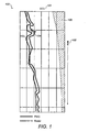
- the invention does this optimization by using real-time PWD data 103 from the well, which is usually displayed in a strip chart as in FIG. 1 .
- a chart plots ECD 101 data, which are Equivalent Circulating Density, a way of measuring Pressure-While-Drilling.
- gathering unit 601 gathers real-time PWD data from a drilling rig, (through a downhole sensor such as an MWD assembly, for example) and an acquiring unit 602 acquires modeled ECD data for the drilling rig.
- An example way to acquire the modeled ECD data is to use modeling software such as DFGTM Software with DrillAhead® Hydraulics Module from HalliburtonTM, which will provide "look-ahead" modeling in which future drilling conditions are predicted.
- the gathering unit 601 and the acquiring unit perform their tasks, the information they provide may be used by a calculating unit 603 for calculating the standard deviation of the differences of said real-time PWD and said modeled ECD data and calculating a set of predicted maximum tolerable ECD data for said drilling process based on the calculated deviations as described in greater detail below. Finally, this information is transmitted to a controlling unit 604 for controlling the drilling rig based on the maximum tolerable ECD data of the drilling process.
- the fracture gradient 105 is clearly far to the right, i.e. higher in ECD value of both the PWD curve 103 and model curve 104.
- the inventors' work has shown that, using the standard deviation of the measured PWD and modeled ECD, estimates can be made as to how close to the fracture gradient one can reliably operate during a drilling process. The smaller the standard deviation, the more confidence one has operating near the fracture gradient.
- Equation 1 Xbar is the average of the PWD data and X i are the discrete-model results for some time period.
- Fracture Gradient data can come from multiple sources. Often one will know the fracture gradient based on offset wells and well testing done on them. Additionally, there are numerous programs that attempts to model and predict pore pressure and fracture gradient based on various properties such as rock type, porosity, temperature etc.
- One good reference on the prediction of fracture gradients is: Pressure Regimes in Sedimentary Basins and Their Prediction by Alan R. Huffman, Glenn L. Bowers, American Association of Petroleum Geologists, American Association of Drilling Engineers, American Association of Petroleum Geologists, American Association of Drilling Engineers Houston Chapter.
- RF represents a reliability factor and SF represents a safety factor.
- the safety factor depends on many factors including the risk (cost) of exceeding ECD and mitigating costs.
- a reasonable SF coupled with an acceptable reliability factor would ensure that ECD would stay below the fracture gradient by a safe margin.
- the user of a given embodiment chooses RF and SF to reflect the margin of error that he or she considers acceptable.
- the standard deviation, ⁇ can be calculated based on a previous "window" of drilling using one of several methods such as a moving average over the well, current bit run, or current formation. Any instability in the standard deviation could immediately be factored into the optimization process by a recalculation of the ECD max ,
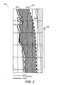
- FIG. 2 shows the calculated ECD max 203 and the safe operating range with a safety factor included. Once again, it is ECD 201 vs. time 202, with PWD recorded 204. The shaded area 205 shows the range of opportunity to increase ECD and maximize the ROP (rate of penetration).
- Cuttings generated during the drilling process must be transported to the surface by the drilling fluid in the annulus.
- the faster the ROP the higher the cuttings concentration becomes in the drilling fluid.
- the average density of the drilling fluid increases as well.
- the increase in drilling fluid density will cause the hydrostatic component of the pressure the drilling fluid exerts on the formation to increase as well.
- the viscosity increase will manifest into higher wellbore pressures as well.
- higher ROP leads to greater ECD tor both of these reasons.
- a cuttings concentrations limit of about 5% has been recommended for vertical wells. As wells have become typically more extended reach, average cuttings concentrations recommendations have been reduced to less than 3%.
- ROP may be determined by means such as a sensor installed on the drill bit which returns the rate at which drilling successfully occurs.
- Table 2 The DAH simulator uses this modified historical data to recreate a real time comparison of modeled ECD to historical PWD data.
- FIG. 3 shows in a strip chart 300 ECD maximum 301, PWD 302, and the Model data 303 as well as the ECD with the 100% increase in the rate of penetration.
- the ECD maximum 301 shows that such an increase is possible, and clearly the same depth can be safely reached in 45 minutes instead of 85 minutes.
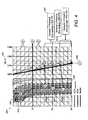
- FIG. 4 represents 3 scenarios where drilling rate of penetration is progressively increased.
- a strip chart 400 shows MD (measured depth) 401 vs. ECD maximum 403, PWD 404 and Modeled ECD 405.
- At 402 are 3 scenarios, marked Scenarios 1, 2, and 3 which show how progressively going faster and faster (while remaining under the fracture gradient) can save $12,500; $20,830, or $29,160; depending on drilling conditions.
- the particular conditions underlying these increased rates of penetration are not important; the important point behind these scenarios are that the embodiments provide the user with progressively faster and faster thresholds that they may opt to implement that can lead to fast, safe drilling as long as the drilling remains within calculated limits.
- the embodiments suggest maximum thresholds for drilling speeds and predict what the results of drilling at intermediate drilling speeds will be.
- the embodiments may be designed to simply drill as fast as possible (given the limits of the rig and the borehole, or to provide the information to drillers and to allow them to choose).
- FIG. 4 shows three look-ahead bit scenarios at 406, 407, 408 (F, G, H). It also shows the interval depth J 409, providing information which will allow the choice of one optimization scenario over the other.
- Table 3 is another example of how SDACE (Selective Drilling Activity Compression/Expansion) might be imposed on real-time data.
- SDACE Selective Drilling Activity Compression/Expansion
- a 50% in ROP combined with a 25% increase in circulation (hole-cleaning) time is shown.
- time is saved because the drilling rate is increased.
- some time is sacrificed to hole-cleaning time.
- this simple example would translate into a 17.5 minute time savings worth about $6076. Bear in mind this is only considering approximately a one hour interval. Repeated throughout a 24-hour day this would realize a savings of $145,824.
- FIG. 5 presents a graph of expected ECD with selective time compression of the drilling process that is used to create simulations of increased ROP.
- ROP data has been artificially increased to determine whether or not ROP could be increased and yet maintain acceptable ECD's below the fracture gradient.
- ROP data has been artificially increased to determine whether or not ROP could be increased and yet maintain acceptable ECD's below the fracture gradient.
- mud formulation changes both with product additions and with actual system selection based on historical/offset data
- a method embodiment shown in FIG. 7 would involve gathering real-time PWD (pressure while drilling) data from a drilling rig sensor 701, acquiring modeled ECD (equivalent circulating density) data for said drilling rig 702, calculating the standard deviation of the differences of said real-time PWD and said modeled ECD data 703, and calculating a set of predicted maximum tolerable ECD data for the drilling process based on the calculated deviation 704 and determining the rate of penetration of the drilling rig based on the maximum tolerable ECD data of the drilling process 704.
- PWD pressure while drilling
- modeled ECD Equivalent circulating density
- the drilling optimization system 600 is illustrated and discussed herein as having various modules and units which perform particular functions and interact with one another. It should be understood that these modules and units are merely segregated based on their function for the sake of description and represent computer hardware and/or executable software code which is stored on a computer-readable medium for execution on appropriate computing hardware. The various functions of the different modules and units can be combined or segregated as hardware and/or software stored on a computer-readable medium as above as modules in any manner, and can be used separately or in combination.
Landscapes
- Life Sciences & Earth Sciences (AREA)
- Engineering & Computer Science (AREA)
- Geology (AREA)
- Mining & Mineral Resources (AREA)
- Physics & Mathematics (AREA)
- Environmental & Geological Engineering (AREA)
- Fluid Mechanics (AREA)
- General Life Sciences & Earth Sciences (AREA)
- Geochemistry & Mineralogy (AREA)
- Earth Drilling (AREA)
- Excavating Of Shafts Or Tunnels (AREA)
Claims (15)
- Procédé destiné à optimiser le taux de pénétration lors d'un forage dans une formation géologique, comprenant les étapes consistant à :collecter des données PWD (pression pendant le forage) en temps réel ;assurer la saisie de données ECD (densité équivalente en circulation) modélisées ;calculer l'écart type des différences desdites données PWD en temps réel et desdites données ECD modélisées ;calculer une ECD tolérable maximale prévue sur la base de l'écart type ayant été calculé ; etdéterminer le taux de pénétration d'un train de tiges de forage, sur la base de l'ECD tolérable maximale d'un processus de forage.
- Procédé selon la revendication 1, lesdites données de l'ECD tolérable maximale prévue étant calculées grâce à l'utilisation dudit écart type à titre de décalage par rapport au gradient de rupture (FG).
- Procédé selon la revendication 1, lesdites données de l'ECD tolérable maximale prévue étant fondées sur (i) un facteur de fiabilité (RF) lequel est multiplié par ledit écart type lorsqu'il est utilisé à titre de décalage par rapport audit gradient de rupture (FG), de préférence cas dans lequel le RF est fondé sur une distribution normale desdites différences ; et/ou (ii) un facteur de sécurité (SF) lequel est ajouté audit écart type lorsqu'il est utilisé à titre de décalage par rapport audit gradient de rupture (FG).
- Procédé selon l'une quelconque des revendications précédentes, comprenant en outre l'étape / les étapes consistant à (i) calculer un ensemble de valeurs d'ECD sous-optimales, mais améliorées, afin de guider ladite vitesse de forage ; et/ou (ii) sélectionner des propriétés de trépan sur la base du taux de pénétration.
- Procédé selon l'une quelconque des revendications précédentes, comprenant l'étape supplémentaire consistant à utiliser des données historiques issues d'itérations antérieures du procédé afin de développer au moins l'un des postes suivants, à savoir :adjonctions de produit pour la formulation de la boue, sélection effective du système et changements opérationnels de procédures.
- Procédé selon la revendication 5, la formulation de la boue modifiant au moins l'un des postes suivants, à savoir : pouvoir lubrifiant, couple, résistance et matières de circulation perdue.
- Procédé selon l'une quelconque des revendications précédentes, ledit taux déterminé de pénétration étant utilisé afin de guider les opérations de forage sur l'installation de forage.
- Système destiné à optimiser le taux de pénétration lors d'un forage dans une formation géologique, comprenant :une unité de collecte pour collecter des données PWD (pression pendant le forage) en temps réel ; etune unité de pilotage pour piloter le taux de pénétration d'un train de tiges de forage sur la base de l'ECD tolérable maximale d'un processus de forage ;caractérisé en ce que le système comporte en outre :une unité de saisie pour assurer la saisie de données ECD (densité équivalente en circulation) modélisées ;une unité de calcul pour calculer l'écart type des différences desdites données PWD en temps réel et desdites données ECD modélisées ; etune unité de calcul pour calculer une ECD tolérable maximale prévue, sur la base de l'écart type ayant été calculé.
- Système selon la revendication 8, lesdites données de l'ECD tolérable maximale prévue étant calculées grâce à l'utilisation dudit écart type à titre de décalage par rapport au gradient de rupture (FG).
- Système selon la revendication 8, lesdites données de l'ECD tolérable maximale prévue étant fondées sur (i) un facteur de fiabilité (RF) lequel est multiplié par ledit écart type lorsqu'il est utilisé à titre de décalage par rapport audit gradient de rupture (FG), de préférence cas dans lequel le RF est fondé sur une distribution normale desdites différences ; et/ou (ii) un facteur de sécurité (SF) lequel est ajouté audit écart type lorsqu'il est utilisé à titre de décalage par rapport audit gradient de rupture (FG).
- Système selon l'une quelconque des revendications 8 à 10, ladite unité de calcul calculant un ensemble de valeurs d'ECD sous-optimales, mais améliorées, afin de guider ladite vitesse de forage.
- Système selon l'une quelconque des revendications 8 à 11, ladite unité de calcul utilisant des données historiques issues d'itérations antérieures du procédé afin de développer au moins l'un des postes suivants, à savoir : adjonctions de produit pour la formulation de la boue, sélection effective du système et changements opérationnels de procédures.
- Système selon la revendication 12, la formulation de la boue modifiant au moins l'un des postes suivants, à savoir : pouvoir lubrifiant, couple, résistance et matières de circulation perdue.
- Système selon l'une quelconque des revendications 8 à 13, l'unité de calcul sélectionnant des propriétés de trépan sur la base du taux de pénétration.
- Système selon l'une quelconque des revendications 8 à 14, comprenant en outre un contrôleur de forage qui utilise le taux déterminé de pénétration afin de guider les opérations de forage sur l'installation de forage.
Applications Claiming Priority (2)
| Application Number | Priority Date | Filing Date | Title |
|---|---|---|---|
| US12/710,445 US8527249B2 (en) | 2010-02-23 | 2010-02-23 | System and method for optimizing drilling speed |
| PCT/GB2011/000248 WO2011104504A2 (fr) | 2010-02-23 | 2011-02-23 | Système et procédé pour optimiser la vitesse de forage |
Publications (2)
| Publication Number | Publication Date |
|---|---|
| EP2539540A2 EP2539540A2 (fr) | 2013-01-02 |
| EP2539540B1 true EP2539540B1 (fr) | 2015-01-21 |
Family
ID=44475545
Family Applications (1)
| Application Number | Title | Priority Date | Filing Date |
|---|---|---|---|
| EP11706903.9A Active EP2539540B1 (fr) | 2010-02-23 | 2011-02-23 | Système et procédé pour optimiser la vitesse de forage |
Country Status (11)
| Country | Link |
|---|---|
| US (1) | US8527249B2 (fr) |
| EP (1) | EP2539540B1 (fr) |
| AR (1) | AR080245A1 (fr) |
| BR (1) | BR112012021000A2 (fr) |
| CA (1) | CA2789219C (fr) |
| CO (1) | CO6602124A2 (fr) |
| DK (1) | DK2539540T3 (fr) |
| EA (1) | EA023817B1 (fr) |
| EC (1) | ECSP12012178A (fr) |
| MX (1) | MX2012009731A (fr) |
| WO (1) | WO2011104504A2 (fr) |
Families Citing this family (31)
| Publication number | Priority date | Publication date | Assignee | Title |
|---|---|---|---|---|
| US9134291B2 (en) | 2012-01-26 | 2015-09-15 | Halliburton Energy Services, Inc. | Systems, methods and devices for analyzing drilling fluid |
| US10175385B2 (en) | 2012-05-23 | 2019-01-08 | Halliburton Energy Services, Inc. | Optimization visualization using normalized achievement variables |
| RU2600497C2 (ru) * | 2012-06-11 | 2016-10-20 | Лэндмарк Графикс Корпорейшн | Способы и относящиеся к ним системы построения моделей и прогнозирования операционных результатов операции бурения |
| AU2013403352B9 (en) * | 2013-10-25 | 2017-02-02 | Landmark Graphics Corporation | Real-time risk prediction during drilling operations |
| AU2013405232B2 (en) * | 2013-11-12 | 2016-11-10 | Halliburton Energy Services, Inc. | Systems and methods for optimizing drilling operations using transient cuttings modeling and real-time data |
| US20150134258A1 (en) * | 2013-11-13 | 2015-05-14 | Schlumberger Technology Corporation | Well Pressure Control Event Detection and Prediction Method |
| US10316653B2 (en) | 2013-11-13 | 2019-06-11 | Schlumberger Technology Corporation | Method for calculating and displaying optimized drilling operating parameters and for characterizing drilling performance with respect to performance benchmarks |
| US10294742B2 (en) * | 2013-11-15 | 2019-05-21 | Halliburton Energy Services, Inc. | Borehole pressure management methods and systems with adaptive learning |
| WO2015102581A1 (fr) * | 2013-12-30 | 2015-07-09 | Halliburton Energy Services, Inc. | Appareil et procédés utilisant des exposants de forabilité |
| US20150300151A1 (en) * | 2014-02-13 | 2015-10-22 | Shahab D. Mohaghegh | System and method providing real-time assistance to drilling operation |
| MX2016014541A (es) * | 2014-05-12 | 2017-02-23 | Nat Oilwell Varco Lp | Metodos para operar equipo de perforacion de pozo basado en las condiciones del pozo. |
| GB2540101B (en) * | 2014-07-08 | 2020-09-09 | Halliburton Energy Services Inc | Real-time optical flow imaging to determine particle size distribution |
| US10145216B2 (en) | 2014-12-02 | 2018-12-04 | Landmark Graphics Corporation | Determining dominant scenarios for slowing down trip speeds |
| CN107995983B (zh) * | 2015-03-06 | 2022-05-06 | 哈佛蒸汽锅炉检验和保险公司 | 用于钻井和完井操作的风险评估 |
| WO2017034586A1 (fr) | 2015-08-27 | 2017-03-02 | Halliburton Energy Services, Inc. | Prédiction de paramètres d'opération de forage |
| CA2992704A1 (fr) | 2015-08-27 | 2017-03-02 | Halliburton Energy Services, Inc. | Ajustement de predictions de parametres d'operation dans un puits de forage |
| CA2992710A1 (fr) | 2015-08-27 | 2017-03-02 | Halliburton Energy Services, Inc. | Determination de sources de predictions de fond de trou erronees |
| US9835026B2 (en) * | 2015-09-28 | 2017-12-05 | Schlumberger Technology Corporation | High-speed transmission of annulus pressure-while-drilling by data compression |
| US10591625B2 (en) | 2016-05-13 | 2020-03-17 | Pason Systems Corp. | Method, system, and medium for controlling rate of penetration of a drill bit |
| WO2018106346A1 (fr) * | 2016-12-07 | 2018-06-14 | Safekick Americas Llc | Forage basé sur un modèle automatisé |
| US20190093468A1 (en) * | 2017-09-27 | 2019-03-28 | Schlumberger Technology Corporation | Real time measurement of mud properties for optimization of drilling parameters |
| US11060399B2 (en) | 2017-11-29 | 2021-07-13 | Halliburton Energy Services, Inc. | Drilling with cuttings density calibration |
| CA3005535A1 (fr) | 2018-05-18 | 2019-11-18 | Pason Systems Corp. | Methode, systeme et milieu de controle du taux de penetration d'un foret |
| US20210017847A1 (en) * | 2019-07-19 | 2021-01-21 | Baker Hughes Oilfield Operations Llc | Method of modeling fluid flow downhole and related apparatus and systems |
| US11280190B2 (en) * | 2019-10-30 | 2022-03-22 | Baker Hughes Oilfield Operations Llc | Estimation of a downhole fluid property distribution |
| US11255189B2 (en) | 2020-05-20 | 2022-02-22 | Halliburton Energy Services, Inc. | Methods to characterize subterranean fluid composition and adjust operating conditions using MEMS technology |
| US11255191B2 (en) * | 2020-05-20 | 2022-02-22 | Halliburton Energy Services, Inc. | Methods to characterize wellbore fluid composition and provide optimal additive dosing using MEMS technology |
| CN113494286B (zh) * | 2021-07-28 | 2023-02-28 | 中国地质大学(武汉) | 一种地质钻进过程钻速智能动态预测方法及系统 |
| CN113408081B (zh) * | 2021-08-14 | 2022-09-02 | 西南石油大学 | 一种基于数据驱动的钻速随钻深层精细化优化方法 |
| US20240418070A1 (en) | 2021-10-22 | 2024-12-19 | Exebenus AS | System and method for predicting and optimizing drilling parameters |
| CN117307062A (zh) * | 2022-06-22 | 2023-12-29 | 中国石油化工股份有限公司 | 一种基于当量循环密度动态监测的钻井管理方法及系统 |
Family Cites Families (8)
| Publication number | Priority date | Publication date | Assignee | Title |
|---|---|---|---|---|
| FR2734315B1 (fr) * | 1995-05-15 | 1997-07-04 | Inst Francais Du Petrole | Methode de determination des conditions de forage comportant un modele de foration |
| US6220087B1 (en) * | 1999-03-04 | 2001-04-24 | Schlumberger Technology Corporation | Method for determining equivalent static mud density during a connection using downhole pressure measurements |
| US6812345B2 (en) * | 2000-06-15 | 2004-11-02 | Bristol-Myers Squibb Company | HMG-CoA reductase inhibitors and method |
| US6722450B2 (en) | 2000-11-07 | 2004-04-20 | Halliburton Energy Svcs. Inc. | Adaptive filter prediction method and system for detecting drill bit failure and signaling surface operator |
| ATE331870T1 (de) * | 2002-12-31 | 2006-07-15 | Schlumberger Services Petrol | Verfahren und vorrichtung zur zeitversetzen analyse von ursache und wirkung |
| US7044239B2 (en) | 2003-04-25 | 2006-05-16 | Noble Corporation | System and method for automatic drilling to maintain equivalent circulating density at a preferred value |
| GB2429484B (en) * | 2004-05-21 | 2009-10-28 | Halliburton Energy Serv Inc | Methods and apparatus for measuring formation properties |
| US8818779B2 (en) * | 2009-12-21 | 2014-08-26 | Baker Hughes Incorporated | System and methods for real-time wellbore stability service |
-
2010
- 2010-02-23 US US12/710,445 patent/US8527249B2/en active Active
-
2011
- 2011-02-22 AR ARP110100538A patent/AR080245A1/es not_active Application Discontinuation
- 2011-02-23 DK DK11706903T patent/DK2539540T3/en active
- 2011-02-23 EP EP11706903.9A patent/EP2539540B1/fr active Active
- 2011-02-23 EA EA201290816A patent/EA023817B1/ru not_active IP Right Cessation
- 2011-02-23 BR BR112012021000A patent/BR112012021000A2/pt active Search and Examination
- 2011-02-23 WO PCT/GB2011/000248 patent/WO2011104504A2/fr not_active Ceased
- 2011-02-23 MX MX2012009731A patent/MX2012009731A/es active IP Right Grant
- 2011-02-23 CA CA2789219A patent/CA2789219C/fr not_active Expired - Fee Related
-
2012
- 2012-09-24 EC ECSP12012178 patent/ECSP12012178A/es unknown
- 2012-09-24 CO CO12165505A patent/CO6602124A2/es unknown
Also Published As
| Publication number | Publication date |
|---|---|
| WO2011104504A3 (fr) | 2012-05-31 |
| EA023817B1 (ru) | 2016-07-29 |
| EP2539540A2 (fr) | 2013-01-02 |
| CO6602124A2 (es) | 2013-01-18 |
| MX2012009731A (es) | 2012-10-01 |
| WO2011104504A2 (fr) | 2011-09-01 |
| BR112012021000A2 (pt) | 2017-07-04 |
| CA2789219C (fr) | 2014-08-05 |
| AR080245A1 (es) | 2012-03-21 |
| ECSP12012178A (es) | 2012-10-30 |
| CA2789219A1 (fr) | 2011-09-01 |
| EA201290816A1 (ru) | 2013-03-29 |
| US20110203845A1 (en) | 2011-08-25 |
| US8527249B2 (en) | 2013-09-03 |
| DK2539540T3 (en) | 2015-03-02 |
Similar Documents
| Publication | Publication Date | Title |
|---|---|---|
| EP2539540B1 (fr) | Système et procédé pour optimiser la vitesse de forage | |
| Moos et al. | Comprehensive wellbore stability analysis utilizing quantitative risk assessment | |
| US11396804B2 (en) | Automated rate of penetration optimization for drilling | |
| CA2863796C (fr) | Modelisation et analyse de propagation de fracture hydraulique vers la surface depuis un sabot de tubage | |
| EP3186476B1 (fr) | Optimisation des opérations de stimulation et de gestion de fluide | |
| CA2492422C (fr) | Systeme d'evaluation des operations de forage sur-equilibrees et sous-equilibrees | |
| US20240070346A1 (en) | Selecting wells for underbalanced coiled tubing drilling in deep and tight gas reservoirs | |
| Etesami et al. | A semiempirical model for rate of penetration with application to an offshore gas field | |
| Bradford et al. | When rock mechanics met drilling: effective implementation of real-time wellbore stability control | |
| GB2439489A (en) | A method for economic evaluation of completion methods for drilling a well | |
| US10301913B2 (en) | Optimizing running operations | |
| US10329882B2 (en) | Optimizing completion operations | |
| Lee et al. | Development of a trip time for bit exchange simulator for drilling time estimation | |
| US20150310367A1 (en) | Systems and methods determining a bit tripping schedule and bit selection based on total cost of drilling | |
| Mayibeki | Drilling optimization of a Caney shale well using offset well drilling data | |
| CN114861958A (zh) | 钻井提速方案的生成方法、装置、设备及存储介质 | |
| Nygaard et al. | Evaluation of automated drilling technologies developed for petroleum drilling and their potential when drilling geothermal wells | |
| US12291955B2 (en) | Real-time model of rig and bit hydraulics efficiency | |
| Miyora et al. | Modelling of geothermal drilling parameters—a case study of well MW-17 in Menengai Kenya | |
| Mostafavi et al. | Assessment and Mitigation of Drilling Risks Using ROP Model Coupled with Monte-Carlo Simulation | |
| TAIWO et al. | SIMULATION-BASED MODELING AND OPTIMIZATION OF DRILLING PARAMETERS INFLUENCING RATE OF PENETRATION IN NIGER DELTA FORMATIONS | |
| Ahmed | SPE/IADC-202176-MS | |
| Nascimento | Modelamento matemático para otimização de perfuração em seções de pré-pal: um foco em operações no oceano Atlântico sul | |
| Kullawan | Faculty of Science and Technology |
Legal Events
| Date | Code | Title | Description |
|---|---|---|---|
| PUAI | Public reference made under article 153(3) epc to a published international application that has entered the european phase |
Free format text: ORIGINAL CODE: 0009012 |
|
| 17P | Request for examination filed |
Effective date: 20120920 |
|
| AK | Designated contracting states |
Kind code of ref document: A2 Designated state(s): AL AT BE BG CH CY CZ DE DK EE ES FI FR GB GR HR HU IE IS IT LI LT LU LV MC MK MT NL NO PL PT RO RS SE SI SK SM TR |
|
| RIN1 | Information on inventor provided before grant (corrected) |
Inventor name: JAMISON, DALE E. Inventor name: WILLIAMS, ROBERT L. Inventor name: PAYLOW, KEVIN P. |
|
| DAX | Request for extension of the european patent (deleted) | ||
| GRAP | Despatch of communication of intention to grant a patent |
Free format text: ORIGINAL CODE: EPIDOSNIGR1 |
|
| INTG | Intention to grant announced |
Effective date: 20140917 |
|
| GRAS | Grant fee paid |
Free format text: ORIGINAL CODE: EPIDOSNIGR3 |
|
| GRAA | (expected) grant |
Free format text: ORIGINAL CODE: 0009210 |
|
| AK | Designated contracting states |
Kind code of ref document: B1 Designated state(s): AL AT BE BG CH CY CZ DE DK EE ES FI FR GB GR HR HU IE IS IT LI LT LU LV MC MK MT NL NO PL PT RO RS SE SI SK SM TR |
|
| REG | Reference to a national code |
Ref country code: GB Ref legal event code: FG4D |
|
| REG | Reference to a national code |
Ref country code: CH Ref legal event code: EP |
|
| REG | Reference to a national code |
Ref country code: IE Ref legal event code: FG4D |
|
| REG | Reference to a national code |
Ref country code: FR Ref legal event code: PLFP Year of fee payment: 5 |
|
| REG | Reference to a national code |
Ref country code: DK Ref legal event code: T3 Effective date: 20150226 |
|
| REG | Reference to a national code |
Ref country code: DE Ref legal event code: R096 Ref document number: 602011013309 Country of ref document: DE Effective date: 20150305 |
|
| REG | Reference to a national code |
Ref country code: AT Ref legal event code: REF Ref document number: 709293 Country of ref document: AT Kind code of ref document: T Effective date: 20150315 |
|
| REG | Reference to a national code |
Ref country code: NL Ref legal event code: T3 |
|
| REG | Reference to a national code |
Ref country code: NL Ref legal event code: T3 |
|
| REG | Reference to a national code |
Ref country code: NL Ref legal event code: T3 |
|
| REG | Reference to a national code |
Ref country code: AT Ref legal event code: MK05 Ref document number: 709293 Country of ref document: AT Kind code of ref document: T Effective date: 20150121 |
|
| REG | Reference to a national code |
Ref country code: LT Ref legal event code: MG4D |
|
| PG25 | Lapsed in a contracting state [announced via postgrant information from national office to epo] |
Ref country code: BE Free format text: LAPSE BECAUSE OF NON-PAYMENT OF DUE FEES Effective date: 20150228 |
|
| REG | Reference to a national code |
Ref country code: NO Ref legal event code: T2 Effective date: 20150121 |
|
| PG25 | Lapsed in a contracting state [announced via postgrant information from national office to epo] |
Ref country code: HR Free format text: LAPSE BECAUSE OF FAILURE TO SUBMIT A TRANSLATION OF THE DESCRIPTION OR TO PAY THE FEE WITHIN THE PRESCRIBED TIME-LIMIT Effective date: 20150121 Ref country code: SE Free format text: LAPSE BECAUSE OF FAILURE TO SUBMIT A TRANSLATION OF THE DESCRIPTION OR TO PAY THE FEE WITHIN THE PRESCRIBED TIME-LIMIT Effective date: 20150121 Ref country code: FI Free format text: LAPSE BECAUSE OF FAILURE TO SUBMIT A TRANSLATION OF THE DESCRIPTION OR TO PAY THE FEE WITHIN THE PRESCRIBED TIME-LIMIT Effective date: 20150121 Ref country code: LT Free format text: LAPSE BECAUSE OF FAILURE TO SUBMIT A TRANSLATION OF THE DESCRIPTION OR TO PAY THE FEE WITHIN THE PRESCRIBED TIME-LIMIT Effective date: 20150121 Ref country code: BG Free format text: LAPSE BECAUSE OF FAILURE TO SUBMIT A TRANSLATION OF THE DESCRIPTION OR TO PAY THE FEE WITHIN THE PRESCRIBED TIME-LIMIT Effective date: 20150421 Ref country code: ES Free format text: LAPSE BECAUSE OF FAILURE TO SUBMIT A TRANSLATION OF THE DESCRIPTION OR TO PAY THE FEE WITHIN THE PRESCRIBED TIME-LIMIT Effective date: 20150121 |
|
| PG25 | Lapsed in a contracting state [announced via postgrant information from national office to epo] |
Ref country code: IS Free format text: LAPSE BECAUSE OF FAILURE TO SUBMIT A TRANSLATION OF THE DESCRIPTION OR TO PAY THE FEE WITHIN THE PRESCRIBED TIME-LIMIT Effective date: 20150521 Ref country code: PL Free format text: LAPSE BECAUSE OF FAILURE TO SUBMIT A TRANSLATION OF THE DESCRIPTION OR TO PAY THE FEE WITHIN THE PRESCRIBED TIME-LIMIT Effective date: 20150121 Ref country code: LV Free format text: LAPSE BECAUSE OF FAILURE TO SUBMIT A TRANSLATION OF THE DESCRIPTION OR TO PAY THE FEE WITHIN THE PRESCRIBED TIME-LIMIT Effective date: 20150121 Ref country code: AT Free format text: LAPSE BECAUSE OF FAILURE TO SUBMIT A TRANSLATION OF THE DESCRIPTION OR TO PAY THE FEE WITHIN THE PRESCRIBED TIME-LIMIT Effective date: 20150121 Ref country code: RS Free format text: LAPSE BECAUSE OF FAILURE TO SUBMIT A TRANSLATION OF THE DESCRIPTION OR TO PAY THE FEE WITHIN THE PRESCRIBED TIME-LIMIT Effective date: 20150121 Ref country code: GR Free format text: LAPSE BECAUSE OF FAILURE TO SUBMIT A TRANSLATION OF THE DESCRIPTION OR TO PAY THE FEE WITHIN THE PRESCRIBED TIME-LIMIT Effective date: 20150422 |
|
| REG | Reference to a national code |
Ref country code: CH Ref legal event code: PL |
|
| REG | Reference to a national code |
Ref country code: DE Ref legal event code: R097 Ref document number: 602011013309 Country of ref document: DE |
|
| PG25 | Lapsed in a contracting state [announced via postgrant information from national office to epo] |
Ref country code: CZ Free format text: LAPSE BECAUSE OF FAILURE TO SUBMIT A TRANSLATION OF THE DESCRIPTION OR TO PAY THE FEE WITHIN THE PRESCRIBED TIME-LIMIT Effective date: 20150121 Ref country code: LI Free format text: LAPSE BECAUSE OF NON-PAYMENT OF DUE FEES Effective date: 20150228 Ref country code: SK Free format text: LAPSE BECAUSE OF FAILURE TO SUBMIT A TRANSLATION OF THE DESCRIPTION OR TO PAY THE FEE WITHIN THE PRESCRIBED TIME-LIMIT Effective date: 20150121 Ref country code: MC Free format text: LAPSE BECAUSE OF FAILURE TO SUBMIT A TRANSLATION OF THE DESCRIPTION OR TO PAY THE FEE WITHIN THE PRESCRIBED TIME-LIMIT Effective date: 20150121 Ref country code: CH Free format text: LAPSE BECAUSE OF NON-PAYMENT OF DUE FEES Effective date: 20150228 Ref country code: EE Free format text: LAPSE BECAUSE OF FAILURE TO SUBMIT A TRANSLATION OF THE DESCRIPTION OR TO PAY THE FEE WITHIN THE PRESCRIBED TIME-LIMIT Effective date: 20150121 Ref country code: RO Free format text: LAPSE BECAUSE OF FAILURE TO SUBMIT A TRANSLATION OF THE DESCRIPTION OR TO PAY THE FEE WITHIN THE PRESCRIBED TIME-LIMIT Effective date: 20150121 |
|
| REG | Reference to a national code |
Ref country code: IE Ref legal event code: MM4A |
|
| PLBE | No opposition filed within time limit |
Free format text: ORIGINAL CODE: 0009261 |
|
| STAA | Information on the status of an ep patent application or granted ep patent |
Free format text: STATUS: NO OPPOSITION FILED WITHIN TIME LIMIT |
|
| 26N | No opposition filed |
Effective date: 20151022 |
|
| PG25 | Lapsed in a contracting state [announced via postgrant information from national office to epo] |
Ref country code: IT Free format text: LAPSE BECAUSE OF FAILURE TO SUBMIT A TRANSLATION OF THE DESCRIPTION OR TO PAY THE FEE WITHIN THE PRESCRIBED TIME-LIMIT Effective date: 20150121 |
|
| REG | Reference to a national code |
Ref country code: FR Ref legal event code: PLFP Year of fee payment: 6 |
|
| PG25 | Lapsed in a contracting state [announced via postgrant information from national office to epo] |
Ref country code: IE Free format text: LAPSE BECAUSE OF NON-PAYMENT OF DUE FEES Effective date: 20150223 |
|
| PG25 | Lapsed in a contracting state [announced via postgrant information from national office to epo] |
Ref country code: SI Free format text: LAPSE BECAUSE OF FAILURE TO SUBMIT A TRANSLATION OF THE DESCRIPTION OR TO PAY THE FEE WITHIN THE PRESCRIBED TIME-LIMIT Effective date: 20150121 |
|
| PGFP | Annual fee paid to national office [announced via postgrant information from national office to epo] |
Ref country code: DE Payment date: 20160302 Year of fee payment: 6 Ref country code: DK Payment date: 20160126 Year of fee payment: 6 |
|
| PG25 | Lapsed in a contracting state [announced via postgrant information from national office to epo] |
Ref country code: BE Free format text: LAPSE BECAUSE OF FAILURE TO SUBMIT A TRANSLATION OF THE DESCRIPTION OR TO PAY THE FEE WITHIN THE PRESCRIBED TIME-LIMIT Effective date: 20150121 |
|
| PGFP | Annual fee paid to national office [announced via postgrant information from national office to epo] |
Ref country code: NL Payment date: 20160205 Year of fee payment: 6 Ref country code: FR Payment date: 20160125 Year of fee payment: 6 |
|
| PG25 | Lapsed in a contracting state [announced via postgrant information from national office to epo] |
Ref country code: MT Free format text: LAPSE BECAUSE OF FAILURE TO SUBMIT A TRANSLATION OF THE DESCRIPTION OR TO PAY THE FEE WITHIN THE PRESCRIBED TIME-LIMIT Effective date: 20150121 |
|
| PG25 | Lapsed in a contracting state [announced via postgrant information from national office to epo] |
Ref country code: SM Free format text: LAPSE BECAUSE OF FAILURE TO SUBMIT A TRANSLATION OF THE DESCRIPTION OR TO PAY THE FEE WITHIN THE PRESCRIBED TIME-LIMIT Effective date: 20150121 Ref country code: HU Free format text: LAPSE BECAUSE OF FAILURE TO SUBMIT A TRANSLATION OF THE DESCRIPTION OR TO PAY THE FEE WITHIN THE PRESCRIBED TIME-LIMIT; INVALID AB INITIO Effective date: 20110223 |
|
| PG25 | Lapsed in a contracting state [announced via postgrant information from national office to epo] |
Ref country code: CY Free format text: LAPSE BECAUSE OF FAILURE TO SUBMIT A TRANSLATION OF THE DESCRIPTION OR TO PAY THE FEE WITHIN THE PRESCRIBED TIME-LIMIT Effective date: 20150121 |
|
| PG25 | Lapsed in a contracting state [announced via postgrant information from national office to epo] |
Ref country code: PT Free format text: LAPSE BECAUSE OF FAILURE TO SUBMIT A TRANSLATION OF THE DESCRIPTION OR TO PAY THE FEE WITHIN THE PRESCRIBED TIME-LIMIT Effective date: 20150521 |
|
| PG25 | Lapsed in a contracting state [announced via postgrant information from national office to epo] |
Ref country code: TR Free format text: LAPSE BECAUSE OF FAILURE TO SUBMIT A TRANSLATION OF THE DESCRIPTION OR TO PAY THE FEE WITHIN THE PRESCRIBED TIME-LIMIT Effective date: 20150121 |
|
| REG | Reference to a national code |
Ref country code: DE Ref legal event code: R119 Ref document number: 602011013309 Country of ref document: DE |
|
| REG | Reference to a national code |
Ref country code: DK Ref legal event code: EBP Effective date: 20170228 |
|
| REG | Reference to a national code |
Ref country code: NL Ref legal event code: MM Effective date: 20170301 |
|
| PG25 | Lapsed in a contracting state [announced via postgrant information from national office to epo] |
Ref country code: NL Free format text: LAPSE BECAUSE OF NON-PAYMENT OF DUE FEES Effective date: 20170301 Ref country code: LU Free format text: LAPSE BECAUSE OF NON-PAYMENT OF DUE FEES Effective date: 20150223 |
|
| REG | Reference to a national code |
Ref country code: FR Ref legal event code: ST Effective date: 20171031 |
|
| PG25 | Lapsed in a contracting state [announced via postgrant information from national office to epo] |
Ref country code: DE Free format text: LAPSE BECAUSE OF NON-PAYMENT OF DUE FEES Effective date: 20170901 Ref country code: FR Free format text: LAPSE BECAUSE OF NON-PAYMENT OF DUE FEES Effective date: 20170228 Ref country code: DK Free format text: LAPSE BECAUSE OF NON-PAYMENT OF DUE FEES Effective date: 20170228 |
|
| PG25 | Lapsed in a contracting state [announced via postgrant information from national office to epo] |
Ref country code: MK Free format text: LAPSE BECAUSE OF FAILURE TO SUBMIT A TRANSLATION OF THE DESCRIPTION OR TO PAY THE FEE WITHIN THE PRESCRIBED TIME-LIMIT Effective date: 20150121 |
|
| PG25 | Lapsed in a contracting state [announced via postgrant information from national office to epo] |
Ref country code: AL Free format text: LAPSE BECAUSE OF FAILURE TO SUBMIT A TRANSLATION OF THE DESCRIPTION OR TO PAY THE FEE WITHIN THE PRESCRIBED TIME-LIMIT Effective date: 20150121 |
|
| PGFP | Annual fee paid to national office [announced via postgrant information from national office to epo] |
Ref country code: GB Payment date: 20241202 Year of fee payment: 15 |
|
| PGFP | Annual fee paid to national office [announced via postgrant information from national office to epo] |
Ref country code: NO Payment date: 20250123 Year of fee payment: 15 |