EP2539964B1 - Elektrisches anschlusselement - Google Patents
Elektrisches anschlusselement Download PDFInfo
- Publication number
- EP2539964B1 EP2539964B1 EP20110761631 EP11761631A EP2539964B1 EP 2539964 B1 EP2539964 B1 EP 2539964B1 EP 20110761631 EP20110761631 EP 20110761631 EP 11761631 A EP11761631 A EP 11761631A EP 2539964 B1 EP2539964 B1 EP 2539964B1
- Authority
- EP
- European Patent Office
- Prior art keywords
- connecting element
- electrical connecting
- element according
- electrical
- soldering
- Prior art date
- Legal status (The legal status is an assumption and is not a legal conclusion. Google has not performed a legal analysis and makes no representation as to the accuracy of the status listed.)
- Active
Links
Images

Classifications
-
- H—ELECTRICITY
- H01—ELECTRIC ELEMENTS
- H01R—ELECTRICALLY-CONDUCTIVE CONNECTIONS; STRUCTURAL ASSOCIATIONS OF A PLURALITY OF MUTUALLY-INSULATED ELECTRICAL CONNECTING ELEMENTS; COUPLING DEVICES; CURRENT COLLECTORS
- H01R4/00—Electrically-conductive connections between two or more conductive members in direct contact, i.e. touching one another; Means for effecting or maintaining such contact; Electrically-conductive connections having two or more spaced connecting locations for conductors and using contact members penetrating insulation
- H01R4/02—Soldered or welded connections
- H01R4/023—Soldered or welded connections between cables or wires and terminals
-
- H—ELECTRICITY
- H01—ELECTRIC ELEMENTS
- H01R—ELECTRICALLY-CONDUCTIVE CONNECTIONS; STRUCTURAL ASSOCIATIONS OF A PLURALITY OF MUTUALLY-INSULATED ELECTRICAL CONNECTING ELEMENTS; COUPLING DEVICES; CURRENT COLLECTORS
- H01R11/00—Individual connecting elements providing two or more spaced connecting locations for conductive members which are, or may be, thereby interconnected, e.g. end pieces for wires or cables supported by the wire or cable and having means for facilitating electrical connection to some other wire, terminal, or conductive member, blocks of binding posts
- H01R11/11—End pieces or tapping pieces for wires, supported by the wire and for facilitating electrical connection to some other wire, terminal or conductive member
- H01R11/12—End pieces terminating in an eye, hook, or fork
-
- H—ELECTRICITY
- H01—ELECTRIC ELEMENTS
- H01R—ELECTRICALLY-CONDUCTIVE CONNECTIONS; STRUCTURAL ASSOCIATIONS OF A PLURALITY OF MUTUALLY-INSULATED ELECTRICAL CONNECTING ELEMENTS; COUPLING DEVICES; CURRENT COLLECTORS
- H01R4/00—Electrically-conductive connections between two or more conductive members in direct contact, i.e. touching one another; Means for effecting or maintaining such contact; Electrically-conductive connections having two or more spaced connecting locations for conductors and using contact members penetrating insulation
- H01R4/02—Soldered or welded connections
-
- H—ELECTRICITY
- H01—ELECTRIC ELEMENTS
- H01R—ELECTRICALLY-CONDUCTIVE CONNECTIONS; STRUCTURAL ASSOCIATIONS OF A PLURALITY OF MUTUALLY-INSULATED ELECTRICAL CONNECTING ELEMENTS; COUPLING DEVICES; CURRENT COLLECTORS
- H01R4/00—Electrically-conductive connections between two or more conductive members in direct contact, i.e. touching one another; Means for effecting or maintaining such contact; Electrically-conductive connections having two or more spaced connecting locations for conductors and using contact members penetrating insulation
- H01R4/58—Electrically-conductive connections between two or more conductive members in direct contact, i.e. touching one another; Means for effecting or maintaining such contact; Electrically-conductive connections having two or more spaced connecting locations for conductors and using contact members penetrating insulation characterised by the form or material of the contacting members
- H01R4/62—Connections between conductors of different materials; Connections between or with aluminium or steel-core aluminium conductors
- H01R4/625—Soldered or welded connections
-
- H—ELECTRICITY
- H01—ELECTRIC ELEMENTS
- H01R—ELECTRICALLY-CONDUCTIVE CONNECTIONS; STRUCTURAL ASSOCIATIONS OF A PLURALITY OF MUTUALLY-INSULATED ELECTRICAL CONNECTING ELEMENTS; COUPLING DEVICES; CURRENT COLLECTORS
- H01R2201/00—Connectors or connections adapted for particular applications
- H01R2201/02—Connectors or connections adapted for particular applications for antennas
-
- H—ELECTRICITY
- H01—ELECTRIC ELEMENTS
- H01R—ELECTRICALLY-CONDUCTIVE CONNECTIONS; STRUCTURAL ASSOCIATIONS OF A PLURALITY OF MUTUALLY-INSULATED ELECTRICAL CONNECTING ELEMENTS; COUPLING DEVICES; CURRENT COLLECTORS
- H01R2201/00—Connectors or connections adapted for particular applications
- H01R2201/26—Connectors or connections adapted for particular applications for vehicles
-
- H—ELECTRICITY
- H01—ELECTRIC ELEMENTS
- H01R—ELECTRICALLY-CONDUCTIVE CONNECTIONS; STRUCTURAL ASSOCIATIONS OF A PLURALITY OF MUTUALLY-INSULATED ELECTRICAL CONNECTING ELEMENTS; COUPLING DEVICES; CURRENT COLLECTORS
- H01R4/00—Electrically-conductive connections between two or more conductive members in direct contact, i.e. touching one another; Means for effecting or maintaining such contact; Electrically-conductive connections having two or more spaced connecting locations for conductors and using contact members penetrating insulation
- H01R4/58—Electrically-conductive connections between two or more conductive members in direct contact, i.e. touching one another; Means for effecting or maintaining such contact; Electrically-conductive connections having two or more spaced connecting locations for conductors and using contact members penetrating insulation characterised by the form or material of the contacting members
-
- H—ELECTRICITY
- H01—ELECTRIC ELEMENTS
- H01R—ELECTRICALLY-CONDUCTIVE CONNECTIONS; STRUCTURAL ASSOCIATIONS OF A PLURALITY OF MUTUALLY-INSULATED ELECTRICAL CONNECTING ELEMENTS; COUPLING DEVICES; CURRENT COLLECTORS
- H01R4/00—Electrically-conductive connections between two or more conductive members in direct contact, i.e. touching one another; Means for effecting or maintaining such contact; Electrically-conductive connections having two or more spaced connecting locations for conductors and using contact members penetrating insulation
- H01R4/58—Electrically-conductive connections between two or more conductive members in direct contact, i.e. touching one another; Means for effecting or maintaining such contact; Electrically-conductive connections having two or more spaced connecting locations for conductors and using contact members penetrating insulation characterised by the form or material of the contacting members
- H01R4/62—Connections between conductors of different materials; Connections between or with aluminium or steel-core aluminium conductors
Definitions
- the invention relates to an electrical connection element for contacting a conductive structure located on a planar support by means of a thermally bonded connecting material, wherein on its side facing away from the conductive structure means for fixing a, preferably flexible, conductor are arranged according to claim 1.
- the electrical connection comprises at least one essentially flat soldering pad to be soldered onto the pane and at least one crimping part, in particular crimp, which is in connection with the soldering pad by welding or soldering and which defines at least one electrical cable in the crimping connection.
- connection between the soldering pad and the crimping part is designed in the form of at least one connecting part, wherein the connecting part is designed such that the crimping part can be bent back into the area of the soldering pad and / or beyond the area of the soldering pad.
- the lead-free solder is based on a Sn in Ag solder alloy containing between 88 to 98.5% by weight Sn, between 1 to 10% by weight In, between 0.5 to 3.5% by weight Ag, between 0 to 1 wt .-% Cu and a doping with a crystallization modifier, in particular a maximum of 100 ppm neodymium.
- This solder should have excellent compatibility with respect to the luting agents used and a high fatigue strength.
- connection elements for a pane and environmentally friendly methods for producing such connection elements have already been proposed.
- the disc has at least one electrical Connection element for vehicles with electrically conductive structures, such as heating or antenna conductor on.
- the electrically conductive structures are contacted via soldered connection elements with the on-board electronics. Due to different thermal expansion coefficients of the materials used, non-negligible mechanical stresses occur during manufacture and subsequent operation, which can stress the disks and cause breakage of the disk or destruction of the contact.
- solders have a high ductility, which is able to absorb or compensate for mechanical stresses between the electrical connection element and the disc.
- the use of leaded solders, however, is problematic in terms of health and environmental aspects and is increasingly avoided.
- connection element for contacting a surface-mounted conductive structure by means of a thermosubstantial connecting material, wherein the choice of the shape and the material of the connection element unavoidable forces due to different expansion coefficients reduced or the effects of the occurring forces are minimized.
- the planar carrier is preferably a pane made of a safety glass, in particular for use in motor vehicle technology.
- the conductive structure is an electrically conductive structure, e.g. a Schuleiteranowski which is realized by means of screen printing, or an antenna structure for operating an on-vehicle radio receiver or other electronic device, e.g. a navigation device.
- the thermal bonding material is a lead-free solder which is located on the side of the electrical connection element which does not have a ferrule or a similar means for fixing a flexible conductor.
- the connecting element according to the invention is designed as a soldering foot, which has one, at least approximate shape of the number eight or an approximate circular ring shape, with one or more interruptions.
- the solder foot consists of two circular rings shaped into the number eight.
- the means for fixing the preferably flexible conductor are located in the surface portion in which the circular rings mesh or touch. Here is enough contact material surface available.
- the thermal bonding material is applied to one side of the terminal member and there occupies an area which is smaller than the annular surface.
- the applied bonding material does not extend to the outer edge of the circular ring, but only up to a predetermined distance range.
- a material-free ring may be present. This ring may also have at least one interruption.
- the bonding material is located as Lötzinn Ronde on the connection element.
- connection element consists of an iron-nickel or iron-chromium alloy or a mixture thereof.
- the connecting element preferably consists of FeCr28, FeNi42, FeNi48 or FeNi52.
- the bonding material comprises, at least as a constituent, the following alloys: Bi57Sn42Ag1, Bi57Sn40Ag3, SnAg3.8Cu0.7, Sn55Bi44Ag1 or Sn95.5Ag3Cu.0.
- connection elements have an expansion coefficient which is very close to the expansion coefficient of car glass panes, namely about 9x10 -6 / K. Resulting stresses are distributed concentrically by the special shape of the soldering foot in the glass and absorbed by the glass material without the risk of destruction.
- the Lötfuß has a circular ring with an inner diameter of 8mm and an outer diameter of 16mm with a material thickness of about 0.8mm.
- the aforementioned eight-form of Lötfußes can also be modified to a double night, without leaving the theory of the invention.
- the electrical connection element is made of a metallic alloy material, e.g. FeCr28, i. an iron-nickel or iron-chromium alloy.
- the connecting element is designed as a soldering foot, which has an at least approximately circular shape.
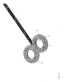
- soldering foot 1 with interlocking circular rings, which give the number eight.
- wire end sleeve 2 On the upper side of the soldering foot 1 there is a wire end sleeve 2, which receives an electrical conductor 3, which has an insulation 4.
- the Lötfuß 1 On the underside, the Lötfuß 1 a Lötzinn Ronde 5, which also has a circular ring shape.
- the Lötzinn Ronde 5 does not reach to the outer edge of the Lötfuß-circular ring, but this has a distance in the Fig. 2 can be seen on.
- the ferrule 2 as means for fixing the conductor 3 is located in a surface portion 6, in which the circular rings mesh or touch.
- the attachment of the ferrule 2 on the Lötfuß 1 takes place, for example. by a welding or soldering process.
- the fixing of the conductor 3 in the wire end sleeve 2 is realized by means of a crimping step.
- the bonding material 5 is made of a lead-free solder-tin alloy, e.g. Bi57Sn42Ag1, Bi57Sn40Ag3, SnAg3.8Cu0.7, Sn55Bi44Ag1 or Sn95.5Ag3Cu0.5.
- a lead-free solder-tin alloy e.g. Bi57Sn42Ag1, Bi57Sn40Ag3, SnAg3.8Cu0.7, Sn55Bi44Ag1 or Sn95.5Ag3Cu0.5.
Landscapes
- Connections Effected By Soldering, Adhesion, Or Permanent Deformation (AREA)
- Coupling Device And Connection With Printed Circuit (AREA)
Description
- Die Erfindung betrifft ein elektrisches Anschlusselement zum Kontaktieren einer auf einem flächigen Träger befindlichen leitfähigen Struktur mittels eines thermisch-stoffschlüssigen Verbindungsmaterials, wobei auf seiner von der leitfähigen Struktur abgewandten Seite Mittel zum Fixieren eines, bevorzugt flexiblen, Leiters angeordnet sind, gemäß Anspruch 1.
- Aus der
DE 202 03 202 U1 ist ein elektrischer Anschluss, insbesondere Crimp- oder Quetschanschluss, für mindestens eine an einer Scheibe eines Fortbewegungsmittels, insbesondere eines Kraftfahrzeugs, anzuordnende elektrische Einrichtung, wie z.B. eine Antenne aufweisend, vorbekannt. Der elektrische Anschluss umfasst mindestens ein im Wesentlichen ebenes, auf die Scheibe aufzulötendes Lötpad und mindestens ein mit dem Lötpad durch Schweißen oder Löten in Verbindung stehendes, mindestens ein elektrisches Kabel im Quetschanschluss festlegendes Quetschteil, insbesondere Crimp. - Gemäß der dortigen Lösung ist die Verbindung zwischen dem Lötpad und dem Quetschteil in Form mindestens eines Verbindungsteils ausgebildet, wobei das Verbindungsteil so ausgestaltet wird, dass das Quetschteil in den Bereich des Lötpads und/oder über den Bereich des Lötpads hinaus zurückbiegbar ist.
- Hierdurch soll eine dauerhafte, stabile und zuverlässige Verbindung zwischen dem Lötpad und dem Quetschteil gewährleistet werden.
- Aus der
DE 10 2006 047 764 A1 ist ein bleifreies Weichlot mit verbesserten Eigenschaften bei Temperaturen um > 150°C vorbekannt. Das bleifreie Weichlot basiert auf einerSn-In-Ag-Lotlegierung, enthaltend zwischen 88 bis 98,5 Gew.-% Sn, zwischen 1 bis 10 Gew.-% In, zwischen 0,5 bis 3,5 Gew.-% Ag, zwischen 0 bis 1 Gew.-% Cu und eine Dotierung mit einem Kristallisations-Modifier, insbesondere maximal 100 ppm Neodym. Dieses Lot soll eine ausgezeichnete Verträglichkeit hinsichtlich der eingesetzten Verbindungsmittel und eine hohe Dauerfestigkeit besitzen. - Darüber hinaus wurden bereits elektrische Anschlusselemente für eine Scheibe sowie umweltfreundliche Verfahren zur Herstellung derartiger Anschlusselemente vorgeschlagen. Die Scheibe weist hierbei mindestens ein elektrisches Anschlusselement für Fahrzeuge mit elektrisch leitfähigen Strukturen, beispielsweise Heizleiter oder Antennenleiter auf. Die elektrisch leitfähigen Strukturen werden über angelötete Anschlusselemente mit der Bordelektronik kontaktiert. Aufgrund unterschiedlicher thermischer Ausdehnungskoeffizienten der verwendeten Materialien treten nicht zu vernachlässigende mechanische Spannungen bei der Herstellung und dem späteren Betrieb auf, welche die Scheiben belasten und einen Bruch der Scheibe oder eine Zerstörung des Kontakts hervorrufen können.
- Bisher genutzte bleihaltige Lote weisen eine hohe Duktilität auf, die in der Lage ist, mechanische Spannungen zwischen elektrischem Anschlusselement und Scheibe aufzunehmen bzw. zu kompensieren. Der Einsatz bleihaltiger Lote ist jedoch unter gesundheitlichen und Umweltaspekten problematisch und wird zunehmend vermieden.
- Da bekannte bleifreie Lote die oben erwähnte Duktilität nicht oder nur eingeschränkt besitzen, gilt es, die bei der Herstellung und/oder dem späteren Betrieb auftretenden mechanischen Spannungen aufgrund unterschiedlicher Ausdehnungskoeffizienten von vornherein zu minimieren.
- Das Dokument
US 6 267 630 offenbart ein elektrisches Anschlusselement gemäss dem Oberbergriff vom Anspruch 1. - Es ist daher Aufgabe der Erfindung, ein weiterentwickeltes elektrisches Anschlusselement zum Kontaktieren einer auf einem flächigen Träger befindlichen leitfähigen Struktur mittels eines thermisch-stoffschlüssigen Verbindungsmaterials anzugeben, wobei durch die Wahl der Form und des Materials des Anschlusselements nicht zu vermeidende Kräfte aufgrund unterschiedlicher Ausdehnungskoeffizienten reduziert bzw. die Auswirkungen der auftretenden Kräfte minimiert werden.
- Die Lösung der Aufgabe der Erfindung erfolgt durch ein elektrisches Anschlusselement gemäß der Merkmalskombination nach Anspruch 1, wobei die Unteransprüche mindestens zweckmäßige Ausgestaltungen und Weiterbildungen umfassen.
- Es wird demnach von einem elektrischen Anschlusselement zum Kontaktieren einer auf einem flächigen Träger befindlichen leitfähigen Struktur ausgegangen.
- Der flächige Träger ist bevorzugt eine Scheibe aus einem Sicherheitsglas, insbesondere zum Einsatz in der Kraftfahrzeugtechnik. Die leitfähige Struktur ist ein elektrisch leitfähiges Gebilde, z.B. eine Heizleiteranordnung, die mittels Siebdruck realisiert wird, oder aber eine Antennenstruktur zum Betrieb eines im Kraftfahrzeug befindlichen Rundfunkempfängers oder eines anderen elektronischen Geräts, z.B. eines Navigationsgeräts.
- Das thermisch-stoffschlüssige Verbindungsmaterial ist ein bleifreies Lot, welches auf der Seite des elektrischen Anschlusselements befindlich ist, welche keine Aderendhülse oder ein ähnliches Mittel zum Befestigen eines flexiblen Leiters besitzt.
- Das erfindungsgemäße Anschlusselement ist als Lötfuß ausgebildet, welcher eine, mindestens angenäherte Form der Zahl Acht oder eine angenäherte Kreisringform, auch mit einer oder mehreren Unterbrechungen besitzt.
- Bei einer Ausführungsform besteht der Lötfuß aus zwei, zu der Zahl Acht geformten Kreisringen.
- Die Mittel zum Fixieren des bevorzugt flexiblen Leiters sind in dem Flächenabschnitt befindlich, in dem die Kreisringe ineinandergreifen oder sich berühren. Hier steht genügend Kontaktmaterialfläche zur Verfügung.
- Das thermisch-stoffschlüssige Verbindungsmaterial wird auf einer Seite des Anschlusselements aufgebracht und nimmt dort eine Fläche ein, die kleiner als die Kreisringfläche ist.
- Bevorzugt reicht das aufgebrachte Verbindungsmaterial nicht bis zum äußeren Kreisringrand, sondern nur bis zu einem vorgegebenen Abstandsbereich. Zusätzlich kann ein materialfreier Ring vorhanden sein. Auch dieser Ring kann mindestens eine Unterbrechung aufweisen.
- Wiederum bevorzugt ist das Verbindungsmaterial als Lötzinn-Ronde auf dem Anschlusselement befindlich.
- Das Anschlusselement besteht aus einer Eisen-Nickel- oder Eisen-Chrom-Legierung oder einer Mischung hieraus.
- Bevorzugt besteht das Anschlusselement aus FeCr28, FeNi42, FeNi48 oder FeNi52.
- Das Verbindungsmaterial weist, mindestens als Bestandteil, folgende Legierungen auf: Bi57Sn42Ag1, Bi57Sn40Ag3, SnAg3.8Cu0.7, Sn55Bi44Ag1 oder Sn95.5Ag3Cu.0.
- Die vorgeschlagenen Materialien für die Anschlusselemente besitzen einen Ausdehnungskoeffizienten, der sehr nahe an dem Ausdehnungskoeffizienten von Autoglasscheiben, nämlich ca. 9x10⁻⁶/K liegt. Entstehende Spannungen werden durch die besondere Form des Lötfußes im Glas konzentrisch verteilt und vom Glasmaterial aufgenommen, ohne dass die Gefahr der Zerstörung besteht.
- Bei einem Ausführungsbeispiel besitzt der Lötfuß einen Kreisring mit einem Innendurchmesser von 8mm und einen Außendurchmesser von 16mm bei einer Materialdicke von ca. 0,8mm. Die vorerwähnte Acht-Form des Lötfußes kann auch zu einer Doppelacht abgewandelt werden, ohne die Erfindungslehre zu verlassen.
- Es hat sich überraschenderweise gezeigt, dass im Gegensatz zu einer vollflächigen Ausführung des Lötfußes bei der vorerwähnten Kreisring- oder kreisringähnlichen Gestaltung wesentlich geringere, Ausdehnungskoeffizientenbedingte Spannungen und Kräfte im Glasmaterial auftreten mit der Folge einer langzeitstabilen und qualitätssicheren elektrischen Verbindung bzw. Kontaktierung.
- Die Erfindung soll nachstehend anhand eines Ausführungsbeispiels sowie unter Zuhilfenahme von Figuren näher erläutert werden.
- Hierbei zeigen:
- Fig. 1
- eine perspektivische Draufsicht auf ein erfindungsgemäßes Anschlusselement mit über eine Aderendhülse angeschlossenem elektrischen Leiter und
- Fig. 2
- eine Darstellung ähnlich derjenigen nach
Fig. 1 , jedoch mit Blick auf die Unterseite des Anschlusselements und dort erkennbarer Lötzinn-Ronde. - Wie in den Figuren dargestellt, besteht das elektrische Anschlusselement aus einem metallischen Legierungsmaterial, z.B. FeCr28, d.h. einer Eisen-Nickel- oder Eisen-Chrom-Legierung.
- Das Anschlusselement ist als Lötfuß ausgebildet, der eine, mindestens angenäherte Kreisringform aufweist.
- Bei den figürlichen Darstellungen wird von einem Lötfuß 1 mit ineinandergreifenden Kreisringen ausgegangen, die die Zahl Acht ergeben. Auf der Oberseite des Lötfußes 1 ist eine Aderendhülse 2 befindlich, die einen elektrischen Leiter 3 aufnimmt, welcher über eine Isolierung 4 verfügt.
- Unterseitig weist der Lötfuß 1 eine Lötzinn-Ronde 5 auf, die ebenfalls eine Kreisringform besitzt.
- Die Lötzinn-Ronde 5 reicht jedoch nicht bis zur Außenkante des Lötfuß-Kreisrings, sondern weist hierzu einen Abstand, in der
Fig. 2 ersichtlich, auf. - Die Aderendhülse 2 als Mittel zum Fixieren des Leiters 3 ist in einem Flächenabschnitt 6 befindlich, in dem die Kreisringe ineinandergreifen oder sich berühren.
- Die Befestigung der Aderendhülse 2 auf dem Lötfuß 1 erfolgt z.B. durch einen Schweiß- oder Lötvorgang.
- Das Fixieren des Leiters 3 in der Aderendhülse 2 wird mittels eines Crimpschritts realisiert.
- Das Verbindungsmaterial 5 geht von einer bleifreien Lötzinn-Legierung, z.B. Bi57Sn42Ag1, Bi57Sn40Ag3, SnAg3.8Cu0.7, Sn55Bi44Ag1 oder Sn95.5Ag3Cu0.5 aus.
- Maßgeblich bei der Ausgestaltung des elektrischen Anschlusselements ist darüber hinaus eine Mindestgröße der Freifläche 7, die vom jeweiligen Kreisring umschlossen wird.
Claims (9)
- Elektrisches Anschlusselement zum Kontaktieren einer auf einem flächigen Träger befindlichen leitfähigen Struktur mittels eines thermisch-stoffschlüssigen Verbindungsmaterials, wobei auf seiner von der leitfähigen Struktur abgewandten Seite Mittel zum Fixieren eines, bevorzugt flexiblen, Leiters angeordnet sind, wobei
das Anschlusselement als Lötfuß (1) ausgebildet ist, welcher eine einfache oder lateral mehrfache Kreisringform besitzt,
dadurch gekennzeichnet, dass
der Lötfuß (1) aus mehreren, ineinandergreifenden Kreisringen oder Kreisringsegmenten besteht. - Elektrisches Anschlusselement nach Anspruch 1,
dadurch gekennzeichnet, dass
der Lötfuß (1) aus zwei, zu der Zahl Acht geformten Kreisringen besteht. - Elektrisches Anschlusselement nach Anspruch 1 oder 2,
dadurch gekennzeichnet, dass
das Mittel zum Fixieren des Leiters (3) in dem Flächenabschnitt (6) befindlich ist, in dem die Kreisringe ineinandergreifen oder sich berühren. - Elektrisches Anschlusselement nach einem der vorangegangenen Ansprüche,
dadurch gekennzeichnet, dass
das thermisch-stoffschlüssige Verbindungselement (5) auf einer Seite des Anschlusselements aufgebracht ist und dort eine Fläche einnimmt, die kleiner als die Kreisringfläche ist. - Elektrisches Anschlusselement nach Anspruch 4,
dadurch gekennzeichnet, dass
das Verbindungsmaterial als Lötzinn-Ronde ausgebildet ist. - Elektrisches Anschlusselement nach einem der vorangegangenen Ansprüche,
dadurch gekennzeichnet, dass
das Anschlusselement aus einer Eisen-Nickel- oder Eisen-Chrom-Legierung oder einer Mischung hieraus besteht. - Elektrisches Anschlusselement nach Anspruch 6,
dadurch gekennzeichnet, dass
dieses aus FeCr28 besteht. - Elektrisches Anschlusselement nach Anspruch 6,
dadurch gekennzeichnet, dass
dieses aus FeNi42, FeNi48 oder FeNi52 besteht. - Elektrisches Anschlusselement nach einem der vorangegangenen Ansprüche,
dadurch gekennzeichnet, dass
das Verbindungsmaterial aus einem bleifreien Lötzinn, insbesondere Bi57Sn42Ag1, Bi57Sn40Ag3, SnAG3.8Cu0.7, Sn55Bi44Ag1 oder besteht.
Applications Claiming Priority (3)
| Application Number | Priority Date | Filing Date | Title |
|---|---|---|---|
| DE202011100176 | 2011-05-03 | ||
| DE202011100906U DE202011100906U1 (de) | 2011-05-03 | 2011-05-19 | Elektrisches Anschlusselement |
| PCT/EP2011/066916 WO2012149985A1 (de) | 2011-05-03 | 2011-09-28 | Elektrisches anschlusselement |
Publications (2)
| Publication Number | Publication Date |
|---|---|
| EP2539964A1 EP2539964A1 (de) | 2013-01-02 |
| EP2539964B1 true EP2539964B1 (de) | 2015-05-06 |
Family
ID=44315775
Family Applications (1)
| Application Number | Title | Priority Date | Filing Date |
|---|---|---|---|
| EP20110761631 Active EP2539964B1 (de) | 2011-05-03 | 2011-09-28 | Elektrisches anschlusselement |
Country Status (9)
| Country | Link |
|---|---|
| US (1) | US9379458B2 (de) |
| EP (1) | EP2539964B1 (de) |
| JP (1) | JP5730440B2 (de) |
| CN (1) | CN103477498B (de) |
| DE (1) | DE202011100906U1 (de) |
| ES (1) | ES2544441T3 (de) |
| HU (1) | HUE026932T2 (de) |
| WO (1) | WO2012149985A1 (de) |
| ZA (1) | ZA201307180B (de) |
Families Citing this family (25)
| Publication number | Priority date | Publication date | Assignee | Title |
|---|---|---|---|---|
| EP2408260A1 (de) * | 2010-07-13 | 2012-01-18 | Saint-Gobain Glass France | Glasscheibe mit einem elektrischen Anschlusselement |
| BR112013028049B1 (pt) * | 2011-05-10 | 2020-10-06 | Saint-Gobain Glass France | Painel com pelo menos um elemento de conexão elétrico,método para produção e uso de tal painel |
| KR101553762B1 (ko) | 2011-05-10 | 2015-09-16 | 쌩-고벵 글래스 프랑스 | 전기 연결 요소를 구비한 창유리 |
| MX2013013015A (es) | 2011-05-10 | 2014-01-31 | Saint Gobain | Hoja de vidrio que comprende un elemento de conexion electrica. |
| DE202012003926U1 (de) | 2012-02-24 | 2012-05-04 | Few Fahrzeugelektrikwerk Gmbh & Co. Kg | Anordnung zum technologisch optimierten Ausführen von Lötverbindungen |
| DE102012007804B4 (de) | 2012-02-24 | 2022-06-02 | Few Fahrzeugelektrikwerk Gmbh & Co. Kg | Verfahren zum technologisch optimierten Ausführen von bleifreien Lötverbindungen |
| WO2013128161A1 (en) | 2012-02-29 | 2013-09-06 | Pilkington Group Limited | Bondable electrical connector and method of utilizing same |
| MY170325A (en) | 2012-09-14 | 2019-07-17 | Saint Gobain | Pane with an electrical connection element |
| PT2896269T (pt) | 2012-09-14 | 2017-06-23 | Saint Gobain | Placa de vidro com um elemento de ligação elétrica |
| ES2621224T3 (es) | 2012-11-21 | 2017-07-03 | Saint-Gobain Glass France | Panel con elemento de conexión eléctrica y alma de unión |
| US9272371B2 (en) | 2013-05-30 | 2016-03-01 | Agc Automotive Americas R&D, Inc. | Solder joint for an electrical conductor and a window pane including same |
| JP6210820B2 (ja) * | 2013-09-30 | 2017-10-11 | 日本板硝子株式会社 | 端子構造体及び車両用のガラス体 |
| DE202014004267U1 (de) * | 2014-05-23 | 2014-07-04 | Few Fahrzeugelektrikwerk Gmbh & Co. Kg | Elektrisches Anschlusselement zum Befestigen, insbesondere Auflöten auf eine Glasscheibe sowie Bandlitzenmischgeflecht |
| DE202015002764U1 (de) | 2014-09-12 | 2015-05-06 | Few Fahrzeugelektrikwerk Gmbh & Co. Kg | Kontaktelement zum Löten mittels elektromagnetischer Induktionserwärmung |
| USD815042S1 (en) * | 2015-03-26 | 2018-04-10 | Few Fahrzeugelektrikwerk Gmbh & Co. Kg | Mounting device |
| EP3089272A1 (de) * | 2015-04-29 | 2016-11-02 | AGC Glass Europe | Verglasung mit einem elektrisch leitfähigen verbinders |
| JP6725971B2 (ja) * | 2015-07-14 | 2020-07-22 | 日本板硝子株式会社 | ガラス板モジュール |
| DE102016219374B4 (de) | 2016-10-06 | 2018-06-14 | Siemens Aktiengesellschaft | Langzeitstabile und stoffschlüssige Strompfadverbindung für Nieder-, Mittelspannungs- und/oder Hochspannungsanlagen bzw. –Schaltgeräte mittels Nanomaterialien |
| USD857420S1 (en) | 2016-12-23 | 2019-08-27 | Few Fahrzeugelektrikwerk Gmbh & Co. Kg | Mounting device |
| DE202016008092U1 (de) | 2016-12-28 | 2017-03-03 | Few Fahrzeugelektrikwerk Gmbh & Co. Kg | Elektrisches Anschlusselement |
| GB201704525D0 (en) | 2017-03-22 | 2017-05-03 | Central Glass Co Ltd | Vehicle glass window with electrical connector soldered by lead-free solder |
| US10263362B2 (en) | 2017-03-29 | 2019-04-16 | Agc Automotive Americas R&D, Inc. | Fluidically sealed enclosure for window electrical connections |
| US10849192B2 (en) | 2017-04-26 | 2020-11-24 | Agc Automotive Americas R&D, Inc. | Enclosure assembly for window electrical connections |
| EP3696916B1 (de) | 2017-11-07 | 2022-07-13 | Central Glass Company, Limited | Fensterscheibenanordnung für kraftfahrzeuge |
| USD927431S1 (en) * | 2018-08-22 | 2021-08-10 | Central Glass Company, Limited | Connecting terminal |
Family Cites Families (16)
| Publication number | Priority date | Publication date | Assignee | Title |
|---|---|---|---|---|
| US3534148A (en) * | 1969-02-11 | 1970-10-13 | Sybron Corp | Encapsulated electrical circuit and terminals and method of making the same |
| US4199214A (en) * | 1979-04-09 | 1980-04-22 | General Motors Corporation | Fused electrical connector |
| JPH01152454U (de) * | 1988-04-14 | 1989-10-20 | ||
| JPH0753272Y2 (ja) * | 1990-05-29 | 1995-12-06 | 日本航空電子工業株式会社 | 同軸コネクタのレセプタクル |
| US5569433A (en) * | 1994-11-08 | 1996-10-29 | Lucent Technologies Inc. | Lead-free low melting solder with improved mechanical properties |
| CN2273058Y (zh) * | 1996-08-28 | 1998-01-21 | 鸿海精密工业股份有限公司 | 电连接器端子 |
| US6475043B2 (en) * | 1998-11-25 | 2002-11-05 | Antaya Technologies Corporation | Circular electrical connector |
| US6267630B1 (en) * | 1999-08-04 | 2001-07-31 | Antaya Technologies Corporation | Circular connector with blade terminal |
| US6406337B1 (en) * | 2000-09-27 | 2002-06-18 | Antaya Technologies Corporation | Glass mounted electrical terminal |
| DE20203202U1 (de) | 2001-12-31 | 2002-06-06 | Gilliam, Jakob, Dipl.-Ing., 82402 Seeshaupt | Elektrischer Anschluß |
| US6685514B2 (en) * | 2002-04-05 | 2004-02-03 | Larry J. Costa | Folding blade electrical terminal |
| US20070224842A1 (en) * | 2004-11-12 | 2007-09-27 | Agc Automotive Americas R&D, Inc. | Electrical Connector For A Window Pane Of A Vehicle |
| DE102006047764A1 (de) | 2006-10-06 | 2008-04-10 | W.C. Heraeus Gmbh | Bleifreies Weichlot mit verbesserten Eigenschaften bei Temperaturen >150°C |
| ES2555652T3 (es) * | 2007-07-16 | 2016-01-07 | Lg Chem, Ltd. | Elemento de conexión eléctrica para batería secundaria |
| DE102008025945A1 (de) * | 2008-05-30 | 2009-12-03 | Fraunhofer-Gesellschaft zur Förderung der angewandten Forschung e.V. | Verfahren zur Herstellung eines vakuumdichten Verbundes zwischen einer Glasscheibe und einem Metallrahmen sowie Glasscheibenverbund |
| EP2408260A1 (de) * | 2010-07-13 | 2012-01-18 | Saint-Gobain Glass France | Glasscheibe mit einem elektrischen Anschlusselement |
-
2011
- 2011-05-19 DE DE202011100906U patent/DE202011100906U1/de not_active Expired - Lifetime
- 2011-09-28 HU HUE11761631A patent/HUE026932T2/hu unknown
- 2011-09-28 JP JP2014508696A patent/JP5730440B2/ja active Active
- 2011-09-28 US US13/504,001 patent/US9379458B2/en active Active
- 2011-09-28 WO PCT/EP2011/066916 patent/WO2012149985A1/de not_active Ceased
- 2011-09-28 ES ES11761631.8T patent/ES2544441T3/es active Active
- 2011-09-28 EP EP20110761631 patent/EP2539964B1/de active Active
- 2011-09-28 CN CN201180070212.1A patent/CN103477498B/zh active Active
-
2013
- 2013-09-25 ZA ZA2013/07180A patent/ZA201307180B/en unknown
Also Published As
| Publication number | Publication date |
|---|---|
| ZA201307180B (en) | 2014-12-23 |
| ES2544441T3 (es) | 2015-08-31 |
| HUE026932T2 (hu) | 2016-07-28 |
| US9379458B2 (en) | 2016-06-28 |
| JP2014514724A (ja) | 2014-06-19 |
| EP2539964A1 (de) | 2013-01-02 |
| JP5730440B2 (ja) | 2015-06-10 |
| CN103477498B (zh) | 2017-06-09 |
| US20120305311A1 (en) | 2012-12-06 |
| DE202011100906U1 (de) | 2011-06-09 |
| WO2012149985A1 (de) | 2012-11-08 |
| CN103477498A (zh) | 2013-12-25 |
Similar Documents
| Publication | Publication Date | Title |
|---|---|---|
| EP2539964B1 (de) | Elektrisches anschlusselement | |
| EP2923528B1 (de) | Scheibe mit elektrischem anschlusselement und verbindungssteg | |
| EP2708091B2 (de) | Scheibe mit einem elektrischen anschlusselement | |
| DE102010018860B4 (de) | Kontaktierungsanordnung für auf flächigen Gebilden, insbesondere Glasscheiben, vorhandene Leiter | |
| DE102006017675A1 (de) | Glasscheibe mit elektrischem Funktionselement mit durch Lötverbindung befestigten Anschlußdrähten und Verfahren zum Herstellen elektrischer Anschlüsse | |
| DE102016125781A1 (de) | Elektrisches Anschlusselement | |
| EP3064034B1 (de) | Scheibe mit mindestens zwei elektrischen anschlusselementen und verbindungsleiter | |
| DE202013012583U1 (de) | Scheibe mit einem elektrischen Anschlusselement | |
| WO2014079595A1 (de) | Scheibe mit elektrischem anschlusselement und kompensatorplatten | |
| EP0374648A2 (de) | Vorrichtung zum Anschluss eines eletrischen Kabels | |
| EP3292737B1 (de) | Scheibe mit elektrischem anschlusselement und daran angebrachtem verbindungselement | |
| DE112013005366T5 (de) | Sicherung und Herstellungsverfahren davon | |
| DE112010005383B4 (de) | Halbleitervorrichtung | |
| DE2515044B2 (de) | Vorrichtung zur elektrischen verbindung einer vielzahl von mit abstand voneinander angeordneten elektrischen leitern | |
| DE102012007804A1 (de) | Verfahren zum technologisch optimierten Ausführen von Lötverbindungen | |
| EP3685479B1 (de) | Litzenkontakt für ein elektrisches bauelement und verfahren zur herstellung eines litzenkontakts | |
| EP2628216B1 (de) | Edelmetallhaltiges kontaktstück auf einem federträger mit rotationssymmetrischem biegemoment | |
| EP2747205B1 (de) | Verfahren zum elektrisch leitenden Verbinden eines Litzenleiters mit einem Kontaktelement | |
| EP2989643B1 (de) | Vorrichtung und verfahren zur herstellung einer elektrisch leitfähigen und mechanischen verbindung | |
| EP3192155A1 (de) | Elektromotor mit smd-bauteilen und zugehöriges verbindungsteil | |
| DE102016219224A1 (de) | Verfahren und Widerstandslötvorrichtung zum Verlöten eines Stromanschlusselements auf einer Fahrzeugscheibe | |
| DE700563C (de) | Befestigung von Anschlussdraehten an elektrischen Widerstaenden | |
| DE102016219225A1 (de) | Fahrzeugscheibe mit Stromanschlusselement und Verfahren zur Herstellung derselben | |
| EP3002997B1 (de) | Elektrisches bauteil mit einem eingriffselement | |
| EP2916391B1 (de) | Leiterplattenanordnung mit flexiblem Verbindungselement |
Legal Events
| Date | Code | Title | Description |
|---|---|---|---|
| PUAI | Public reference made under article 153(3) epc to a published international application that has entered the european phase |
Free format text: ORIGINAL CODE: 0009012 |
|
| 17P | Request for examination filed |
Effective date: 20120416 |
|
| AK | Designated contracting states |
Kind code of ref document: A1 Designated state(s): AL AT BE BG CH CY CZ DE DK EE ES FI FR GB GR HR HU IE IS IT LI LT LU LV MC MK MT NL NO PL PT RO RS SE SI SK SM TR |
|
| RIC1 | Information provided on ipc code assigned before grant |
Ipc: H01R 4/02 20060101AFI20140625BHEP |
|
| DAX | Request for extension of the european patent (deleted) | ||
| GRAP | Despatch of communication of intention to grant a patent |
Free format text: ORIGINAL CODE: EPIDOSNIGR1 |
|
| INTG | Intention to grant announced |
Effective date: 20141119 |
|
| GRAS | Grant fee paid |
Free format text: ORIGINAL CODE: EPIDOSNIGR3 |
|
| GRAA | (expected) grant |
Free format text: ORIGINAL CODE: 0009210 |
|
| AK | Designated contracting states |
Kind code of ref document: B1 Designated state(s): AL AT BE BG CH CY CZ DE DK EE ES FI FR GB GR HR HU IE IS IT LI LT LU LV MC MK MT NL NO PL PT RO RS SE SI SK SM TR |
|
| REG | Reference to a national code |
Ref country code: GB Ref legal event code: FG4D Free format text: NOT ENGLISH |
|
| REG | Reference to a national code |
Ref country code: CH Ref legal event code: EP |
|
| REG | Reference to a national code |
Ref country code: IE Ref legal event code: FG4D Free format text: LANGUAGE OF EP DOCUMENT: GERMAN |
|
| REG | Reference to a national code |
Ref country code: AT Ref legal event code: REF Ref document number: 726256 Country of ref document: AT Kind code of ref document: T Effective date: 20150615 |
|
| REG | Reference to a national code |
Ref country code: DE Ref legal event code: R096 Ref document number: 502011006806 Country of ref document: DE Effective date: 20150618 |
|
| REG | Reference to a national code |
Ref country code: ES Ref legal event code: FG2A Ref document number: 2544441 Country of ref document: ES Kind code of ref document: T3 Effective date: 20150831 |
|
| REG | Reference to a national code |
Ref country code: FR Ref legal event code: PLFP Year of fee payment: 5 |
|
| REG | Reference to a national code |
Ref country code: NL Ref legal event code: MP Effective date: 20150506 |
|
| REG | Reference to a national code |
Ref country code: LT Ref legal event code: MG4D |
|
| PG25 | Lapsed in a contracting state [announced via postgrant information from national office to epo] |
Ref country code: HR Free format text: LAPSE BECAUSE OF FAILURE TO SUBMIT A TRANSLATION OF THE DESCRIPTION OR TO PAY THE FEE WITHIN THE PRESCRIBED TIME-LIMIT Effective date: 20150506 Ref country code: PT Free format text: LAPSE BECAUSE OF FAILURE TO SUBMIT A TRANSLATION OF THE DESCRIPTION OR TO PAY THE FEE WITHIN THE PRESCRIBED TIME-LIMIT Effective date: 20150907 Ref country code: LT Free format text: LAPSE BECAUSE OF FAILURE TO SUBMIT A TRANSLATION OF THE DESCRIPTION OR TO PAY THE FEE WITHIN THE PRESCRIBED TIME-LIMIT Effective date: 20150506 Ref country code: NO Free format text: LAPSE BECAUSE OF FAILURE TO SUBMIT A TRANSLATION OF THE DESCRIPTION OR TO PAY THE FEE WITHIN THE PRESCRIBED TIME-LIMIT Effective date: 20150806 Ref country code: FI Free format text: LAPSE BECAUSE OF FAILURE TO SUBMIT A TRANSLATION OF THE DESCRIPTION OR TO PAY THE FEE WITHIN THE PRESCRIBED TIME-LIMIT Effective date: 20150506 |
|
| PG25 | Lapsed in a contracting state [announced via postgrant information from national office to epo] |
Ref country code: GR Free format text: LAPSE BECAUSE OF FAILURE TO SUBMIT A TRANSLATION OF THE DESCRIPTION OR TO PAY THE FEE WITHIN THE PRESCRIBED TIME-LIMIT Effective date: 20150807 Ref country code: RS Free format text: LAPSE BECAUSE OF FAILURE TO SUBMIT A TRANSLATION OF THE DESCRIPTION OR TO PAY THE FEE WITHIN THE PRESCRIBED TIME-LIMIT Effective date: 20150506 Ref country code: IS Free format text: LAPSE BECAUSE OF FAILURE TO SUBMIT A TRANSLATION OF THE DESCRIPTION OR TO PAY THE FEE WITHIN THE PRESCRIBED TIME-LIMIT Effective date: 20150906 Ref country code: BG Free format text: LAPSE BECAUSE OF FAILURE TO SUBMIT A TRANSLATION OF THE DESCRIPTION OR TO PAY THE FEE WITHIN THE PRESCRIBED TIME-LIMIT Effective date: 20150806 Ref country code: LV Free format text: LAPSE BECAUSE OF FAILURE TO SUBMIT A TRANSLATION OF THE DESCRIPTION OR TO PAY THE FEE WITHIN THE PRESCRIBED TIME-LIMIT Effective date: 20150506 |
|
| PG25 | Lapsed in a contracting state [announced via postgrant information from national office to epo] |
Ref country code: EE Free format text: LAPSE BECAUSE OF FAILURE TO SUBMIT A TRANSLATION OF THE DESCRIPTION OR TO PAY THE FEE WITHIN THE PRESCRIBED TIME-LIMIT Effective date: 20150506 Ref country code: DK Free format text: LAPSE BECAUSE OF FAILURE TO SUBMIT A TRANSLATION OF THE DESCRIPTION OR TO PAY THE FEE WITHIN THE PRESCRIBED TIME-LIMIT Effective date: 20150506 |
|
| REG | Reference to a national code |
Ref country code: DE Ref legal event code: R097 Ref document number: 502011006806 Country of ref document: DE |
|
| PG25 | Lapsed in a contracting state [announced via postgrant information from national office to epo] |
Ref country code: PL Free format text: LAPSE BECAUSE OF FAILURE TO SUBMIT A TRANSLATION OF THE DESCRIPTION OR TO PAY THE FEE WITHIN THE PRESCRIBED TIME-LIMIT Effective date: 20150506 Ref country code: RO Free format text: LAPSE BECAUSE OF NON-PAYMENT OF DUE FEES Effective date: 20150506 |
|
| REG | Reference to a national code |
Ref country code: SK Ref legal event code: T3 Ref document number: E 19559 Country of ref document: SK |
|
| PLBE | No opposition filed within time limit |
Free format text: ORIGINAL CODE: 0009261 |
|
| STAA | Information on the status of an ep patent application or granted ep patent |
Free format text: STATUS: NO OPPOSITION FILED WITHIN TIME LIMIT |
|
| 26N | No opposition filed |
Effective date: 20160209 |
|
| PG25 | Lapsed in a contracting state [announced via postgrant information from national office to epo] |
Ref country code: LU Free format text: LAPSE BECAUSE OF FAILURE TO SUBMIT A TRANSLATION OF THE DESCRIPTION OR TO PAY THE FEE WITHIN THE PRESCRIBED TIME-LIMIT Effective date: 20150928 Ref country code: MC Free format text: LAPSE BECAUSE OF FAILURE TO SUBMIT A TRANSLATION OF THE DESCRIPTION OR TO PAY THE FEE WITHIN THE PRESCRIBED TIME-LIMIT Effective date: 20150506 Ref country code: IT Free format text: LAPSE BECAUSE OF FAILURE TO SUBMIT A TRANSLATION OF THE DESCRIPTION OR TO PAY THE FEE WITHIN THE PRESCRIBED TIME-LIMIT Effective date: 20150506 |
|
| REG | Reference to a national code |
Ref country code: CH Ref legal event code: PL |
|
| GBPC | Gb: european patent ceased through non-payment of renewal fee |
Effective date: 20150928 |
|
| PG25 | Lapsed in a contracting state [announced via postgrant information from national office to epo] |
Ref country code: SI Free format text: LAPSE BECAUSE OF FAILURE TO SUBMIT A TRANSLATION OF THE DESCRIPTION OR TO PAY THE FEE WITHIN THE PRESCRIBED TIME-LIMIT Effective date: 20150506 |
|
| REG | Reference to a national code |
Ref country code: IE Ref legal event code: MM4A |
|
| REG | Reference to a national code |
Ref country code: HU Ref legal event code: AG4A Ref document number: E026932 Country of ref document: HU |
|
| PG25 | Lapsed in a contracting state [announced via postgrant information from national office to epo] |
Ref country code: IE Free format text: LAPSE BECAUSE OF NON-PAYMENT OF DUE FEES Effective date: 20150928 Ref country code: LI Free format text: LAPSE BECAUSE OF NON-PAYMENT OF DUE FEES Effective date: 20150930 Ref country code: CH Free format text: LAPSE BECAUSE OF NON-PAYMENT OF DUE FEES Effective date: 20150930 Ref country code: GB Free format text: LAPSE BECAUSE OF NON-PAYMENT OF DUE FEES Effective date: 20150928 |
|
| REG | Reference to a national code |
Ref country code: FR Ref legal event code: PLFP Year of fee payment: 6 |
|
| PGFP | Annual fee paid to national office [announced via postgrant information from national office to epo] |
Ref country code: ES Payment date: 20161024 Year of fee payment: 6 |
|
| PG25 | Lapsed in a contracting state [announced via postgrant information from national office to epo] |
Ref country code: MT Free format text: LAPSE BECAUSE OF FAILURE TO SUBMIT A TRANSLATION OF THE DESCRIPTION OR TO PAY THE FEE WITHIN THE PRESCRIBED TIME-LIMIT Effective date: 20150506 |
|
| PG25 | Lapsed in a contracting state [announced via postgrant information from national office to epo] |
Ref country code: SM Free format text: LAPSE BECAUSE OF FAILURE TO SUBMIT A TRANSLATION OF THE DESCRIPTION OR TO PAY THE FEE WITHIN THE PRESCRIBED TIME-LIMIT Effective date: 20150506 |
|
| PG25 | Lapsed in a contracting state [announced via postgrant information from national office to epo] |
Ref country code: SE Free format text: LAPSE BECAUSE OF FAILURE TO SUBMIT A TRANSLATION OF THE DESCRIPTION OR TO PAY THE FEE WITHIN THE PRESCRIBED TIME-LIMIT Effective date: 20150506 Ref country code: NL Free format text: LAPSE BECAUSE OF FAILURE TO SUBMIT A TRANSLATION OF THE DESCRIPTION OR TO PAY THE FEE WITHIN THE PRESCRIBED TIME-LIMIT Effective date: 20150506 Ref country code: CY Free format text: LAPSE BECAUSE OF FAILURE TO SUBMIT A TRANSLATION OF THE DESCRIPTION OR TO PAY THE FEE WITHIN THE PRESCRIBED TIME-LIMIT Effective date: 20150506 |
|
| PG25 | Lapsed in a contracting state [announced via postgrant information from national office to epo] |
Ref country code: BE Free format text: LAPSE BECAUSE OF NON-PAYMENT OF DUE FEES Effective date: 20150930 |
|
| PG25 | Lapsed in a contracting state [announced via postgrant information from national office to epo] |
Ref country code: TR Free format text: LAPSE BECAUSE OF FAILURE TO SUBMIT A TRANSLATION OF THE DESCRIPTION OR TO PAY THE FEE WITHIN THE PRESCRIBED TIME-LIMIT Effective date: 20150506 |
|
| REG | Reference to a national code |
Ref country code: AT Ref legal event code: MM01 Ref document number: 726256 Country of ref document: AT Kind code of ref document: T Effective date: 20160928 |
|
| REG | Reference to a national code |
Ref country code: FR Ref legal event code: PLFP Year of fee payment: 7 |
|
| PG25 | Lapsed in a contracting state [announced via postgrant information from national office to epo] |
Ref country code: AT Free format text: LAPSE BECAUSE OF NON-PAYMENT OF DUE FEES Effective date: 20160928 |
|
| PGFP | Annual fee paid to national office [announced via postgrant information from national office to epo] |
Ref country code: FR Payment date: 20180129 Year of fee payment: 7 |
|
| PG25 | Lapsed in a contracting state [announced via postgrant information from national office to epo] |
Ref country code: MK Free format text: LAPSE BECAUSE OF FAILURE TO SUBMIT A TRANSLATION OF THE DESCRIPTION OR TO PAY THE FEE WITHIN THE PRESCRIBED TIME-LIMIT Effective date: 20150506 |
|
| REG | Reference to a national code |
Ref country code: ES Ref legal event code: FD2A Effective date: 20181017 |
|
| PG25 | Lapsed in a contracting state [announced via postgrant information from national office to epo] |
Ref country code: AL Free format text: LAPSE BECAUSE OF FAILURE TO SUBMIT A TRANSLATION OF THE DESCRIPTION OR TO PAY THE FEE WITHIN THE PRESCRIBED TIME-LIMIT Effective date: 20150506 |
|
| PG25 | Lapsed in a contracting state [announced via postgrant information from national office to epo] |
Ref country code: ES Free format text: LAPSE BECAUSE OF NON-PAYMENT OF DUE FEES Effective date: 20170929 |
|
| PG25 | Lapsed in a contracting state [announced via postgrant information from national office to epo] |
Ref country code: FR Free format text: LAPSE BECAUSE OF NON-PAYMENT OF DUE FEES Effective date: 20180930 |
|
| PGFP | Annual fee paid to national office [announced via postgrant information from national office to epo] |
Ref country code: SK Payment date: 20190911 Year of fee payment: 9 |
|
| PGFP | Annual fee paid to national office [announced via postgrant information from national office to epo] |
Ref country code: HU Payment date: 20191002 Year of fee payment: 9 |
|
| REG | Reference to a national code |
Ref country code: SK Ref legal event code: MM4A Ref document number: E 19559 Country of ref document: SK Effective date: 20200928 |
|
| PG25 | Lapsed in a contracting state [announced via postgrant information from national office to epo] |
Ref country code: SK Free format text: LAPSE BECAUSE OF NON-PAYMENT OF DUE FEES Effective date: 20200928 |
|
| PG25 | Lapsed in a contracting state [announced via postgrant information from national office to epo] |
Ref country code: HU Free format text: LAPSE BECAUSE OF NON-PAYMENT OF DUE FEES Effective date: 20200929 |
|
| P01 | Opt-out of the competence of the unified patent court (upc) registered |
Effective date: 20230621 |
|
| PGFP | Annual fee paid to national office [announced via postgrant information from national office to epo] |
Ref country code: CZ Payment date: 20250916 Year of fee payment: 15 |
|
| PGFP | Annual fee paid to national office [announced via postgrant information from national office to epo] |
Ref country code: DE Payment date: 20250930 Year of fee payment: 15 |