EP2540152A1 - Presses à balles améliorées et procédés de formation de balles à haute densité - Google Patents
Presses à balles améliorées et procédés de formation de balles à haute densité Download PDFInfo
- Publication number
- EP2540152A1 EP2540152A1 EP20120174118 EP12174118A EP2540152A1 EP 2540152 A1 EP2540152 A1 EP 2540152A1 EP 20120174118 EP20120174118 EP 20120174118 EP 12174118 A EP12174118 A EP 12174118A EP 2540152 A1 EP2540152 A1 EP 2540152A1
- Authority
- EP
- European Patent Office
- Prior art keywords
- crop material
- baler
- compression rollers
- pressure
- pair
- Prior art date
- Legal status (The legal status is an assumption and is not a legal conclusion. Google has not performed a legal analysis and makes no representation as to the accuracy of the status listed.)
- Granted
Links
Images


Classifications
-
- A—HUMAN NECESSITIES
- A01—AGRICULTURE; FORESTRY; ANIMAL HUSBANDRY; HUNTING; TRAPPING; FISHING
- A01F—PROCESSING OF HARVESTED PRODUCE; HAY OR STRAW PRESSES; DEVICES FOR STORING AGRICULTURAL OR HORTICULTURAL PRODUCE
- A01F15/00—Baling presses for straw, hay or the like
- A01F15/08—Details
- A01F15/0825—Regulating or controlling density or shape of the bale
-
- A—HUMAN NECESSITIES
- A01—AGRICULTURE; FORESTRY; ANIMAL HUSBANDRY; HUNTING; TRAPPING; FISHING
- A01F—PROCESSING OF HARVESTED PRODUCE; HAY OR STRAW PRESSES; DEVICES FOR STORING AGRICULTURAL OR HORTICULTURAL PRODUCE
- A01F15/00—Baling presses for straw, hay or the like
- A01F15/07—Rotobalers, i.e. machines for forming cylindrical bales by winding and pressing
-
- A—HUMAN NECESSITIES
- A01—AGRICULTURE; FORESTRY; ANIMAL HUSBANDRY; HUNTING; TRAPPING; FISHING
- A01F—PROCESSING OF HARVESTED PRODUCE; HAY OR STRAW PRESSES; DEVICES FOR STORING AGRICULTURAL OR HORTICULTURAL PRODUCE
- A01F15/00—Baling presses for straw, hay or the like
- A01F15/08—Details
-
- A—HUMAN NECESSITIES
- A01—AGRICULTURE; FORESTRY; ANIMAL HUSBANDRY; HUNTING; TRAPPING; FISHING
- A01F—PROCESSING OF HARVESTED PRODUCE; HAY OR STRAW PRESSES; DEVICES FOR STORING AGRICULTURAL OR HORTICULTURAL PRODUCE
- A01F15/00—Baling presses for straw, hay or the like
- A01F15/08—Details
- A01F15/10—Feeding devices for the crop material e.g. precompression devices
Definitions
- the present disclosure relates generally to improved balers and methods for forming high density bales of crop materials, for example, miscanthus, switchgrass, small grain straws, corn cobs, or stover.
- balers For many years agricultural balers have been used to consolidate and package crop material so as to facilitate the storage and handling of the crop material for later use.
- a mower-conditioner cuts and conditions the crop material for windrow drying in the sun.
- a baler for example a round baler, travels along the windrows to pick up the crop material and form it into cylindrically-shaped round bales.
- a pick-up assembly of the baler gathers the cut and windrowed crop material from the ground then conveys the cut crop material into a bale-forming chamber (or bale chamber) within the baler.
- a drive mechanism operates to activate the pick-up assembly, augers, and a rotor of the feed mechanism.
- a conventional bale chamber may include of a pair of opposing sidewalls with a series of belts, chains, and/or rolls that rotate and compress the crop material into a cylindrical shaped bale.
- Square balers operate on similar principles but form "slices" which when stacked together form a rectangular or "square” bale.
- Certain dry crop materials such as miscanthus, switchgrass, small grain straws, or a mix of corn cobs and stover have a relatively low bulk density in traditional bales, either round or square. Densities can range from 7 to 14 pound/square feet. To be able to take advantage of trucking capacities, the U.S. Department of Energy has targeted 15.5 pound/square feet as a goal to improve transportation and logistic costs. Moreover, crop materials with stems having nodes and/or internodes also have a relatively low bulk density in round or square traditional bales.
- High density bales are desirable because they would allow people to take advantage of transportation capacities and will reduce the numbers of the bales to work with.
- the present invention is directed to these and other important ends
- Embodiments of the present invention provides improved balers and methods for forming high density bales.
- the present disclosure provides a baler comprising a pick-up assembly; a compression assembly comprising at least one pair of opposing compression rollers configured to generate a pressure on crop material passed therethrough, the at least one pair of opposing compression rollers defining an adjustable gap therebetween, the compression assembly being configured to crush the crop material passed therethrough; and a bale chamber, wherein the crushed crop forms a bale.
- to crush comprises destroying the structural integrity of an individual stem of crop material so that the individual stem may not spring back.
- to crush further comprises flattening a majority of one or more nodes or internodes so that the nodes or internodes do not spring back, wherein the nodes and internodes are located along the stems of the crop material.
- the majority is a number of nodes or internodes greater than about seventy percent of the nodes and internodes in the crop material.
- the opposing compression rollers are configured to generate a pressure on the crop material greater than about fifty pound/linear square inch. According to one embodiment of the invention, the opposing compression rollers are configured to generate a pressure on the crop material based on the type of crop material being crushed. According to another aspect of one embodiment of the invention, the crop material comprises at least one of: miscanthus, switchgrass, small grain straws, corn cobs, or stover. According to one embodiment of the invention, the opposing compression rollers are configured to generate a pressure on the crop material based on the amount of crop material being crushed.
- the pressure may vary as the crop material passes therethrough the at least one pair of opposing compression rollers.
- the compression rollers comprise a saw tooth pattern to improve passage of the crop mater through the baler in addition to crushing the crop material passed therethrough the at least one pair of opposing compression rollers.
- the present disclosure provides a method for crushing a crop material to form a high density bale.
- the method comprises picking up crop material by a pick-up assembly; crushing the crop material by a compression assembly, wherein the compression assembly comprising at least one pair of opposing compression rollers configured to generate a pressure on crop material passed therethrough, the at least one pair of opposing compression rollers defining an adjustable gap therebetween, the compression assembly being configured to crush the crop material passed therethrough; and baling the crushed material by a bale chamber to form a bale.
- crushing comprises destroying the structural integrity of an individual stem of crop material so that the individual stem may not spring back.
- crushing further comprises flattening a majority of nodes or internodes so that the nodes or internodes do not spring back and wherein the nodes and internodes are located along the stems of the crop material.
- the method further includes configuring the at least one pair of opposing compression rollers to generate a pressure greater than about fifty pound/linear square inch on the crop material.
- the method further includes adjusting, by a controller, the gap between the at least one pair of opposing compression rollers of the compression assembly to vary the pressure generated by the at least one pair of opposing compression rollers on the crop material passed therethrough.
- the method further comprises adjusting the gap to vary the pressure based on the type of crop material being crushed.
- the method further includes adjusting the gap to vary the pressure based on the amount of crop material being crushed.
- the method further includes feeding the crop material with a saw tooth on the compression rollers to improve passage of the crop material through the baler in addition to crushing the crop material passed therethrough.
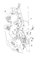
- FIG. 1 illustrates a cutaway side elevational view of an exemplary square baler according to an embodiment
- FIG. 2 illustrates a side view of a pick-up assembly, a pair of rotor and cutter, a pair of opposing compression roller, pre-chamber, a bale chamber of an exemplary square baler of the present invention
- FIG. 3 shows a side view of an exemplary round baler of the present invention
- FIG. 4 illustrates an exemplary process for forming high-density bales according to an embodiment
- FIG. 5 illustrates an exemplary process for obtaining sensor readings and adjusting the performance of a baler according to an embodiment.
- FIG. 6 illustrates an exemplary single acting hydraulic pressure control system according to an embodiment.
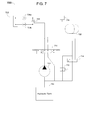
- FIG. 7 illustrates an exemplary double acting hydraulic pressure control system according to an embodiment.
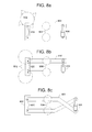
- FIGS. 8a-c illustrate various mounting systems and arrangements for compression rollers according to an embodiment.
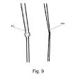
- FIG. 9 illustrates an exemplary comparison of crop material pieces according to an embodiment.
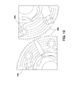
- FIG. 10 illustrates an exemplary saw tooth pattern on compression rollers according to an embodiment.
- the present invention provides an improved baler for forming high density bales of crop materials, for example, those having a relatively low bulk density in traditional bales (such as miscanthus, switchgrass, small grain straws, corn cobs, stover) or those having stems that includes nodes and internodes.
- the baler of the present invention can be either for square bales or round bales.
- FIG. 1 illustrates an exemplary square baler according to an embodiment of the present invention.
- a baler or baling apparatus
- a pre-chamber 11 that forms a slice of bale material.
- the pre-formed slice may be injected into the main bale chamber where a bale is formed.
- the pre-chamber 11 of the square baler may be positioned between a pick-up assembly and a bale chamber 19.
- the pick-up assembly may include pick-up tines 16, optional baffle plates 17, and one or more centering augers 15.
- the pick-up tines 16, baffle plates 17 and centering augers 15 may work in concert to pick up crop material 60 and align it for conveyance toward the pre-chamber 11.
- the crop material 60 may pass through a gap between one pair of opposing compression rollers, the pair including a lower roller 100a and an upper roller 100b.
- the gap between the two rollers may be adjustable.
- one compression roller of the pair of opposing compression rollers (for example, the lower roller 100a) is fixed to a frame of the baler, and the other compression roller of the pair of opposing compression rollers (for example, the upper roller 100b) is floating (e.g., adjustably supported on the baler frame).
- each of the compression rollers of the pair of opposing compression rollers is floating (adjustably supported on the baler frame).
- the lower roller 100a and the upper roller 100b may be linked together, for example, by a hydraulic cylinder 105, a spring, or the like, to generate a pre-defined pressure on the crop material 60 passing therethrough. By applying the pressure to the crop material 60, the lower roller 100a and the upper roller 100b may act to crush the crop material.
- a hydraulic cylinder (such as the hydraulic cylinder 105 in FIG. 1 ) may be used to provide a reading of the pressure generated by the pair of opposing compression rollers on the crop material 60 passed therethrough.
- the lower roller 100a and the upper roller 100b may be driven by a motor to rotate towards one another so that the crop material 60 may be fed into the gap between the pair of rollers and may be crushed by the pair of the roller as the rollers rotate.
- to crush a crop material refers to decreasing/destroying the structural integrity of the each individual stem of the crop material so that it does not spring back.
- a stem of a crop material has one or more nodes and/or internodes.
- crushing the crop material includes crushing the majority (for example, greater than about 70%, 75%, 80%, 85%, 90%, 95%, 98%, or 99%) of the nodes and/or internodes (the crushed nodes and/or internodes are flattened and will not spring back).
- the pre-defined pressure generated by the pair of opposing compression rollers to crush crop material passed therethrough depends on the nature of the crop material. In some embodiments, the predefined pressure generated by the lower roller 100a and the upper roller 100b to crush crop material passed therethrough is greater than about 50 pound/linear square inch, about 60 pound/linear square inch, about 70 pound/linear square inch, about 80 pound/linear square inch, about 90 pound/linear square inch, or about 100 pound/linear square inch.
- pressures described herein are shown by way of example only. Additional pressures may be used during operation of the compression rollers. For example, if a mat of crop material is passed between the compression rollers, a force of about 400 pounds/linear square inch may be applied to the compression rollers to crush a high percentage of the crop nodes. Various pressures may be determined based upon the type of crop being crushed as well as the amount of crop material being crushed simultaneously and may vary during the operation of the compression rollers.
- the gap between the lower roller and the upper roller may be adjusted, depending, for example, on the nature and thickness of the crop material that is to pass through the gap (e.g., the thickness of the crop matt).
- a controller 115 may be coupled to the pressure sensor 110, and adjustment of the gap between a pair of opposing compression rollers is automatically controlled by the controller. In other further embodiments, adjustment of the gap between the pair of opposing compression rollers is manually controlled by an operator of the baler.
- the gap between the lower roller 100a and the upper roller 100b may have a minimum value or threshold that is always maintained.
- the minimum value or threshold may be about 1.0 cm, about 1.2 cm, 1.3 cm, 1.4 cm, 1.5 cm, or about 2 cm.
- gaps discussed above are shown by way of example only.
- the actual gap between the compression roller during operation may vary accordingly based upon a number of factors, including but not limited to, amount of crop being crushed simultaneously, forward speed of the baler, type of crop being crushed, and other similar factors.
- the localization of crushing the crop material will reduce equipment requirements for other parts of the baler such as the bale chamber where bales are formed, for example, by a plunger.
- a denser crop material is fed to the bale chamber.
- the size and associated crushing/stacking force required for the baler forming device may be lowered as the crop material is already crushed. This may also reduce any hydraulic requirements associated with the bale chamber as the force asserted on the crop material is reduced as a result of the crop material being crushed locally at the compression rollers.
- rollers for the compression rollers that crush the crop materials (i.e., the lower roller 100a and the upper roller 100b).
- the material and/or surface design of the rollers can be used as parameters for selection of rollers.
- a metal roller such as steel or stainless steel roller
- a spiral roller or a high contact roller can be suitable because the small surface features of the spiral roller or the high contact roller can provide crop traction and the large flat surfaces can be suitable to crush the crop at high pressures.
- a roller or rollers with a saw tooth pattern 1000 can be used to improve crop material feeding in addition to crushing crop materials.
- the saw tooth pattern 1000 shown is on both the lower roller 100a and upper roller 100b. The selection of suitable rollers also depends, in part, on the crop materials to be crushed.
- the speed of the lower roller 100a and the upper roller 100b may be synchronized with the other parts of the baler.
- the pick-up assembly and the bale chamber 19 may be synchronized with the lower roller 100a and the upper roller 100b.
- the capacity of the lower roller 100a and the upper roller 100b matches the capacity of the pick-up assembly and the capacity of the bale chamber 19, and thus the entire baler operates efficiently with a minimized risk of overcollection/clogging.
- the thickness of the crop material that is to pass through the lower roller 100a and the upper roller 100b may be determined by factors such as the speed of the pick-up assembly and the distance between the pick-up assembly and the pair of opposing compression rollers.
- an optional series of packer forks; an optional rotary feeder mechanism; or a pair of rotary feeder and cutter can be employed, for example, to control the thickness of the crop material that is to pass through the pair of opposing compression rollers.
- a crop material (not shown) may be picked up via a pick-up assembly 70 and may pass a rotary feeder 71 and a cutter 72. From here, the crop material may pass through a gap between a lower fixed roller 73a and an upper floating roller 73b. As before, the lower fixed roller 73a and upper floating roller 73b may be configured and arranged such that they generate a pre-determined pressure to crush the crop materials passed therethrough. The crushed material then passes a material sensor or "hay dog" 75 into the pre-chamber 76 and then to bale chamber 77 where bales are formed.
- the baler further comprises a speed sensor 125 or a group of speed sensors.
- the speed sensor(s) 125 may be configured to detect the speeds of the pick-up assembly, the pair of opposing compression rollers (e.g., lower roller 100a and upper roller 100b), and the bale chamber 77.
- the baler may comprise a controller 130 or a group of the controllers coupled to the speed sensor(s) 125, wherein the synchronization of the pick-up assembly 70, the pair of opposing compression rollers 73a and 73b, and the bale chamber 77 may be automatically controlled by the controller.
- the synchronization of the pick-up assembly 70, the pair of opposing compression rollers 73a and 73b, and the bale chamber 77 may be manually controlled by an operator of the baler.
- the crop material may pass an optional element 14, which may be forks or a rotor fork, configured and positioned to convey the crushed crop material into the pre-chamber 11 where it is partially compressed.
- the pre-chamber 11 may be used to establish how much crushed crop material 60 is in each slice.
- a baler operator may regulate the amount of material in one slice by varying parameters associated with the pre-chamber 11. Once that amount is reached, the material in the pre-chamber 11 may be injected into the bale chamber 19 by a crop holding finger, stuffer fork, and/or arm 12.
- a plunger which may be continually driving like a piston in an engine, compresses the bale, forcing a slice, in FIG. 1 from left to right in the bale chamber 19. In this manner, slices are pushed to the right, as shown in FIG. 1 , and compressed while forming the bale.
- Square balers are well known in the agricultural industry, and the pick-assembly, pre-chamber, and bale chamber of any of such machines can be used in the square baler of the present invention. Examples of square balers can be found in U.S. Application No. 12/871,439, filed August 30, 2010 and entitled “Method of Tagging Square Bales,” the content of which is hereby incorporated by reference in its entirety.
- FIG. 3 shows an embodiment of the present invention including an exemplary round baler.
- a pick-up assembly 200 may pick up crop material 205.
- an optional feeder roller 210 may feed the crop material 205 through a gap between a pair of opposing compression rollers, specifically roller 220a and roller 220b, which are configured and positioned to generate a pre-defined pressure on the crop material passed therethrough to crush the crop material.
- the roller 220a and the roller 220b may be similar in construction to the lower roller 100a and the upper roller 100b as shown in FIG. 1 .
- the roller 220a and the roller 220b may be linked together, for example, by a hydraulic cylinder (such as hydraulic cylinder 225), a spring, or the like.
- the hydraulic cylinder 225 may be configured to generate a pre-defined pressure on the crop material 205 passed through the rollers 220a and 220b to crush the crop material.
- the gap between the rollers 220a and 220b may be adjustable.
- either roller 220a or roller 220b may be fixed to a frame of the baler while the other roller is floating (e.g., adjustably supported on the baler frame).
- each of the rollers 220a and 220b may be floating (e.g., adjustably supported on the baler frame).
- the pre-defined pressure generated by the rollers 220a and 220b to crush the crop material 205 passed therethrough may depend on the nature of the crop material. In some embodiments, the predefined pressure generated by the rollers 220a and 220b to crush the crop material 205 passed therethrough is greater than about 50 pound/linear square inch, about 60 pound/linear square inch, about 70 pound/linear square inch, about 80 pound/linear square inch, about 90 pound/linear square inch, or about 100 pound/linear square inch.
- a sensor and/or a controller e.g., pressure sensor 110 and controller 115 as shown in FIG. 1 ) may be employed to sense and/or control the gap between roller 220a and roller 220b and/or the pressure generated by roller 220a and roller 220b on crop materials 205 passed therethrough.
- the crop material 205 crushed by roller 220a and roller 220b may then pass to starter roller 230 and floor roller 240, and a bale chamber 250 where a round bale 260 is formed.
- the speed of the pair of opposing rollers 220a and 220b may be synchronized with the other parts of the baler (e.g., the pick-up assembly and the bale chamber).
- the capacity of the pair of opposing rollers 220a and 220b may match the capacity of the pick-up assembly 200 and the capacity of the bale chamber 250, and thus the entire baler operates without major congestion or clogging of crop material.
- One or more sensors and/ or a controller e.g., speed sensor 125 and controller 130 as shown in FIG. 2 ) may be employed to detect and control the speed of the pick-up assembly 200, the pair of opposing rollers 220a and 220b, and the bale chamber 250.
- Round balers are well known in the agricultural industry, and the pick-assembly and bale chamber of any of such machines can be used in the round baler of the present invention. Examples of round balers can be found in U.S. Patent Nos. 7,437,866 , 6,877,304 ; 6,688,092 ; 6,644,006 and 6,295,797 , the content of each of which is hereby incorporated by reference in its entirety.
- the balers of the present invention may be configured to form high density bales. Comparing to a prior art baler (or a conventional baler), a baler of the present invention can improve the density of a baler by at least about 15%, 30%, 50%, 80%, 100%, 150%, or 200%.
- FIG. 4 illustrates an exemplary process for forming a high density bale according to an embodiment of the present invention.
- crop materials are picked up 400 by a pick-up assembly (e.g., pick-up assembly 200 as shown in FIG. 3 ).
- the crop materials may be crushed 402 via a compression assembly.
- Exemplary compression assemblies are discussed above in regard to lower roller 100a and upper roller 100b, and rollers 220a and 220b.
- the compression assembly asserts a crushing pressure to the crop materials, resulting in a crushed crop material.
- the crop material is baled 404 via a bale chamber (e.g., bale chamber 19 as shown in FIG. 1 or bale chamber 250 as shown in FIG. 3 ).
- bale chamber e.g., bale chamber 19 as shown in FIG. 1 or bale chamber 250 as shown in FIG. 3 ).
- two or more components of the baler may be synchronized 406.
- the pick-up assembly, the compression assembly and the bale chamber may be synchronized 406 such that operation of the baler is performed smoothly without any clogging or congestion of crop material.
- FIG. 5 illustrates an exemplary process for utilizing one or more sensors to optimize high density bale formation as well as the overall performance of a baler.
- a pressure sensor e.g., pressure sensor 110 as shown in FIG. 1
- a speed sensor e.g., speed sensor 125 as shown in FIG. 2
- this is shown for exemplary purposes only. Only one of the sensors may be used, or additional sensors may be added depending on the manufacture and intended use of the baler.
- one or more controllers receives 500 various input values from the sensors.
- the controller may compare 502 the current pressure value received 500 from a pressure sensor against the pre-defined pressure value.
- the pre-defined pressure value may be based upon the type of crop material being baled as well as the desired density of the bales being formed.
- the controller may adjust 504 the gap between the opposing compression rollers by sending a signal to a hydraulic cylinder linking the two rollers to either increase or decrease the gap.
- the gap may be manually adjusted by an operator of the baler to maintain the current pressure value as close to the pre-defined pressure value as possible.
- the controller may determine 506 the speed of various components of the baler based upon the values received 500 from the sensors. For example, the controller may determine 506 the speed of the pick-up assembly, the compression rollers and the bale chamber. The controller may then adjust 508 the speed of one or more of the components in order to synchronize the components, thereby optimizing the throughput of the baler. Alternatively, the speed of the components by be manually adjusted by an operator of the baler.
- the controller may receive 500 additional values from the sensor(s) and continue the process illustrated in FIG. 5 until operation of the baler is completed.
- the pressure and speed adjustment paths are shown in parallel for exemplary purposes only. The adjustments may occur simultaneously as shown in FIG. 5 , sequentially one after the other, or according to a set pattern. For example, the pressure exerted by the compression rollers may be determined and adjusted once a minute while the speed of the individual components is monitored and adjusted every 15 seconds.
- FIG. 6 illustrates an exemplary single action hydraulic pressure control system 600 for use with a set of compression rollers.
- the system 600 may include at least one compression roller assembly 602.
- the compression roller assembly may include a pair of compression rollers 604a and 604b as well as a hydraulic cylinder 606.
- a pump 608 may pump hydraulic fluid from a hydraulic tank 610 to the hydraulic cylinder 606 via one or more valves.
- the pump 606 may pump hydraulic fluid through a pressure increase valve 612 and an isolation valve 614.
- the isolation valve 614 may be included to isolate the compression roller assembly 602 from any other components on the hydraulic system 600.
- the hydraulic system may also include a pressure release valve 616 for return of pressurized hydraulic fluid to the hydraulic tank 610.
- the hydraulic system may also include a pressure sensor 618 and a hydraulic accumulator 620.
- the hydraulic accumulator 620 may be positioned and configured to reduce pressure variation in hydraulic pressure in the hydraulic system 600 as the hydraulic cylinder 606 moves. Under demand, i.e., during operation of the baler, the hydraulic cylinder 606 may move as the crop mat thickness changes, thereby causing potential pressure variations in the hydraulic system 600.
- the Hydraulic accumulator 620 may act as a pressure reservoir to reduce these pressure variations.
- the pressure sensor 618 may be operably connected to a baler monitoring and/or control system for monitoring the pressure in the hydraulic system 600.
- FIG. 7 illustrates an exemplary double action hydraulic pressure control system 700 for use with a set of compression rollers.
- the system 700 may include at least one compression roller assembly 702.
- the compression roller assembly may include a pair of compression rollers 704a and 704b as well as a hydraulic cylinder 706.
- a pump 708 may pump hydraulic fluid from a hydraulic tank 710 to the hydraulic cylinder 706 via one or more valves.
- the pump 706 may pump hydraulic fluid through a double action pressure valve 712.
- the double action pressure valve 712 may be configured to operate as both a pressure increase valve and a pressure decrease valve.
- a two-port unloading valve 714 may be included to provide a manual means for removing any pressurized hydraulic fluid from the hydraulic system 700.
- Hydraulic system 700 may further include a pressure relief valve 716.
- the pressure relief valve 716 may be configured to reduce the pressure exerted by the compression rollers 704a and 704b if a foreign object is fed into the baler with the crop material. For example, if a rock is fed into the baler and passed between the compression rollers 704a and 704b, the relief valve 716 may release the pressure on the compression rollers rather than damage the rollers trying to crush the rock.
- the hydraulic system may also include a pressure sensor 718 and a hydraulic accumulator 720.
- the hydraulic accumulator 720 may be positioned and configured to reduce pressure variation in hydraulic pressure in the hydraulic system 700 as the hydraulic cylinder 706 moves. Under demand, i.e., during operation of the baler, the hydraulic cylinder 706 may move as the crop mat thickness changes, thereby causing potential pressure variations in the hydraulic system 700.
- the Hydraulic accumulator 720 may act as a pressure reservoir to reduce these pressure variations.
- the pressure sensor 718 may be operably connected to a baler monitoring and/or control system for monitoring the pressure in the hydraulic system 700.
- FIGS. 8a-c illustrates various mounting configurations for the compression rollers.
- FIG. 8a illustrates an exemplary mounting configuration for use with a rotary feeder 802.
- the pair of compression rollers 804 may be mounted on a steel frame 806.
- Two or more pivot points or pin joints 810 may be included to allow various components of the steel frame to pivot, thus allowing the compression rollers 804 to move forward or away from each other.
- the pressure exerted on crop material by the compression rollers 804 may be determined by a hydraulic pressure cylinder 808 in combination with the thickness of the crop material being crushed.
- the hydraulic cylinder 808 may extend and contract accordingly, depending upon the thickness and density of the crop material, to maintain a constant crushing force.
- the hydraulic pressure at a rod end of the hydraulic cylinder 808 may also increase, thereby extending the hydraulic cylinder and moving the compression rollers further apart, thereby maintaining a constant crushing force exerted on the crop material.
- the hydraulic pressure at the rod end of the hydraulic cylinder 808 may also decrease, thereby contracting the hydraulic cylinder and moving the compression rollers 804 closer together.
- FIG. 8b illustrates a similar configuration as FIG. 8a .
- a pair of converging rollers 812 may feed crop material to a pair of compression rollers 814.
- the pair of compression rollers 814 may be mounted on a steel frame 816.
- Two or more pivot points or pin joints 820 may be included to allow various components of the steel frame to pivot, thus allowing the compression rollers 814 to move forward or away from each other.
- the pressure exerted on crop material by the compression rollers 814 may be determined by a hydraulic pressure cylinder 818 in combination with the thickness of the crop material being crushed.
- the hydraulic cylinder 818 may extend and contract accordingly, depending upon the thickness and density of the crop material, to maintain a constant crushing force.
- the hydraulic pressure at a rod end of the hydraulic cylinder 818 may also increase, thereby extending the hydraulic cylinder and moving the compression rollers further apart, thereby maintaining a constant crushing force exerted on the crop material.
- the hydraulic pressure at the rod end of the hydraulic cylinder 818 may also decrease, thereby contracting the hydraulic cylinder and moving the compression rollers 814 closer together.
- FIG. 8c illustrates an alternative arrangement.
- the compression rollers 824 may be mounted on an X-shaped steel frame 826 having two crossing arms. Each arm may be pivotably attached to cross-member 822. Two or more pivot points or pin joints 830 may be included to allow various components of the steel frame to pivot, thus allowing the compression rollers 824 to move forward or away from each other.
- the pressure exerted on crop material by the compression rollers 824 may be determined by a hydraulic pressure cylinder 828 in combination with the thickness of the crop material being crushed.
- the hydraulic cylinder 828 may extend and contract accordingly, depending upon the thickness and density of the crop material, to maintain a constant crushing force.
- FIG. 828 illustrates an alternative arrangement.
- the X-shape of the steel frame 826 results in inverted motion related to the extension and contraction of the hydraulic cylinder. For example, if the thickness of the crop material increases, the hydraulic pressure at a rod end of the hydraulic cylinder 828 may decrease, thereby contracting the hydraulic cylinder and moving the compression rollers further apart, thereby maintaining a constant crushing force exerted on the crop material. Conversely, if the thickness of the crop material decreases, the hydraulic pressure at the rod end of the hydraulic cylinder 828 may increase, thereby extending the hydraulic cylinder and moving the compression rollers 824 closer together.
- FIG. 9 illustrates an exemplary view of two pieces of crop material.
- Crop material piece 902 has not been crushed and thus has an intact node.
- Crop material piece 904 has been crushed via a pair of compression rollers. The node of piece 904 has been crushed.
- the crop material may be more densely baled, resulting in more crop material per bale and thus more efficient collection and transportation of the crop material.
- two or more sets of opposing compression rollers may be used in series.
- Formation of higher density bales is advantageous in the handling and transportation of bales. Formation of higher density bales is also advantageous to support the growing biomass industry.
Landscapes
- Life Sciences & Earth Sciences (AREA)
- Environmental Sciences (AREA)
- Harvesting Machines For Specific Crops (AREA)
- Disintegrating Or Milling (AREA)
- Fodder In General (AREA)
Applications Claiming Priority (1)
| Application Number | Priority Date | Filing Date | Title |
|---|---|---|---|
| US13/175,285 US9173347B2 (en) | 2011-07-01 | 2011-07-01 | Balers and methods for forming high density bales |
Publications (2)
| Publication Number | Publication Date |
|---|---|
| EP2540152A1 true EP2540152A1 (fr) | 2013-01-02 |
| EP2540152B1 EP2540152B1 (fr) | 2016-12-14 |
Family
ID=46397061
Family Applications (1)
| Application Number | Title | Priority Date | Filing Date |
|---|---|---|---|
| EP12174118.5A Active EP2540152B1 (fr) | 2011-07-01 | 2012-06-28 | Presses à balles améliorées et procédés de formation de balles à haute densité |
Country Status (2)
| Country | Link |
|---|---|
| US (1) | US9173347B2 (fr) |
| EP (1) | EP2540152B1 (fr) |
Cited By (4)
| Publication number | Priority date | Publication date | Assignee | Title |
|---|---|---|---|---|
| CN105409481A (zh) * | 2015-12-08 | 2016-03-23 | 山东省农业机械科学研究院 | 玉米秸秆打捆机 |
| CN107306531A (zh) * | 2017-08-15 | 2017-11-03 | 黑龙江省农业机械运用研究所 | 一种玉米秸秆深埋还田工艺 |
| BE1024820B1 (de) * | 2016-04-20 | 2018-07-13 | Claas Saulgau Gmbh | Einzugvorrichtung für einen Feldhäcksler |
| DE102024110681A1 (de) * | 2024-04-16 | 2025-10-16 | Ingo Dreher | Vorrichtung und Verfahren zum Bereitstellen von Ballen sowie System und Verfahren zum Verwerten von Ballen |
Families Citing this family (7)
| Publication number | Priority date | Publication date | Assignee | Title |
|---|---|---|---|---|
| US10165730B2 (en) * | 2013-07-31 | 2019-01-01 | Cnh Industrial America Llc | Method of operating an agricultural baler |
| GB2549945A (en) * | 2016-05-03 | 2017-11-08 | Kverneland Group Kerteminde As | Conditioner unit |
| BE1026244B1 (nl) * | 2018-05-04 | 2019-12-02 | Cnh Ind Belgium Nv | Intelligente baalvorming |
| EP4066623A1 (fr) * | 2021-03-31 | 2022-10-05 | CNH Industrial Belgium N.V. | Véhicule agricole avec plaque de guidage flottante |
| US12336457B2 (en) * | 2022-06-23 | 2025-06-24 | Deere & Company | Auxiliary pressure circuit for a round baler |
| EP4371399B1 (fr) * | 2022-11-18 | 2025-12-10 | McHale Engineering Unlimited Company | Presse à balles et procédé pour augmenter la densité d'une balle dans une presse à balles |
| US20260076309A1 (en) | 2024-09-16 | 2026-03-19 | Cnh Industrial America Llc | Twin roller windguard |
Citations (9)
| Publication number | Priority date | Publication date | Assignee | Title |
|---|---|---|---|---|
| FR1239827A (fr) * | 1959-11-05 | 1960-08-26 | Cima Cie Internationale Des Ma | Rouleaux arracheurs de tiges de récoltes battues sur pied ou étêtées |
| EP0467283A2 (fr) * | 1990-07-18 | 1992-01-22 | Karl Mengele & Söhne, Maschinenfabriken GmbH & Co. | Presse à balles pour récoltes agricoles |
| EP0995352A1 (fr) * | 1998-10-21 | 2000-04-26 | Case Harvesting Systems GmbH | Rouleau conditionneur et procédé de sa fabrication pour faucheuse-hacheuse |
| US6295797B1 (en) | 1999-02-18 | 2001-10-02 | New Holland North America, Inc. | Movable windguard |
| US6546705B2 (en) | 2000-05-13 | 2003-04-15 | New Holland North America, Inc. | Method and apparatus for controlling a tractor/baler combination |
| US6644006B1 (en) | 2002-07-19 | 2003-11-11 | New Holland North America, Inc. | Remote reverse control for pick-up rotor |
| US6688092B2 (en) | 2002-01-14 | 2004-02-10 | Deere & Company | Pick-up crop baffle including integral crop hold down rods and suspension for use in widely varied crops |
| US6877304B1 (en) | 2004-07-31 | 2005-04-12 | Cnh America Llc | Windguard for round baler |
| US7437866B2 (en) | 2006-12-20 | 2008-10-21 | Cnh America Llc | Sensor for bale shape monitoring in round balers |
Family Cites Families (21)
| Publication number | Priority date | Publication date | Assignee | Title |
|---|---|---|---|---|
| US2469580A (en) | 1944-03-08 | 1949-05-10 | Allis Chalmers Mfg Co | Rotary baler |
| US4446678A (en) | 1980-09-24 | 1984-05-08 | Smith Teddy V | Material processing machinery |
| US4803832A (en) * | 1981-06-22 | 1989-02-14 | Massey-Ferguson Inc. | Method and apparatus for forming bales |
| NL8304137A (nl) * | 1983-12-01 | 1985-07-01 | Lely Nv C Van Der | Inrichting voor het vormen van balen gewas. |
| US4510741A (en) * | 1984-03-19 | 1985-04-16 | Gehl Company | Rotary crop baler |
| US4912914A (en) | 1988-08-29 | 1990-04-03 | Wingard Steve G | Method and apparatus for drying forage crops |
| JPH0695841B2 (ja) | 1989-09-29 | 1994-11-30 | 日本たばこ産業株式会社 | 残幹処理方法及び残幹処理装置 |
| US5052170A (en) | 1990-06-14 | 1991-10-01 | Trenkamp Michael J | Shredder attachment for round hay baler |
| DE4228857A1 (de) * | 1992-08-29 | 1994-03-03 | Kloeckner Humboldt Deutz Ag | Vorrichtung zur Halmgutaufbereitung |
| IT1260425B (it) | 1992-12-07 | 1996-04-05 | Dispositivo condizionatore di foraggio per piegamento | |
| DE4344585A1 (de) | 1993-12-24 | 1995-06-29 | Kloeckner Humboldt Deutz Ag | Vorrichtung zur Halmgutaufbereitung |
| DE19539143B4 (de) * | 1995-10-20 | 2005-03-17 | Claas Kgaa Mbh | Einzugsvorrichtung für Feldhäcksler |
| US6032446A (en) | 1998-04-06 | 2000-03-07 | Deere & Company | Densification method and apparatus for harvested cotton or other similar fibrous material |
| AUPQ289699A0 (en) * | 1999-09-16 | 1999-10-07 | Mackie International Pty Ltd | Hay conditioning |
| US6655121B1 (en) * | 2000-08-10 | 2003-12-02 | Gehl Company | Powered feed roller system for a round baler |
| US6601375B1 (en) | 2001-08-10 | 2003-08-05 | Gehl Company | Wide pickup and feeding system for supplying crop material to the crop inlet of an agricultural implement |
| US6820542B1 (en) | 2001-10-05 | 2004-11-23 | Bobby L. Truitt | Leaf compactor and baler |
| FR2866518B1 (fr) * | 2004-02-23 | 2007-07-13 | Guy Dehondt | Procede et machine pour conditionner en balles des plantes fibreuses, notamment du lin, du chanvre et du sisal. |
| US7743595B2 (en) | 2007-07-06 | 2010-06-29 | Her Majesty The Queen In Right Of Canada As Represented By The Minister Of Agriculture And Agri-Food Canada | Device and method for harvesting woody crops |
| US8291687B2 (en) * | 2009-07-31 | 2012-10-23 | Agco Corporation | Continuous round baler |
| US8820040B2 (en) * | 2011-07-01 | 2014-09-02 | Cnh Industrial America Llc | Compression rolls on baler pick up |
-
2011
- 2011-07-01 US US13/175,285 patent/US9173347B2/en active Active
-
2012
- 2012-06-28 EP EP12174118.5A patent/EP2540152B1/fr active Active
Patent Citations (9)
| Publication number | Priority date | Publication date | Assignee | Title |
|---|---|---|---|---|
| FR1239827A (fr) * | 1959-11-05 | 1960-08-26 | Cima Cie Internationale Des Ma | Rouleaux arracheurs de tiges de récoltes battues sur pied ou étêtées |
| EP0467283A2 (fr) * | 1990-07-18 | 1992-01-22 | Karl Mengele & Söhne, Maschinenfabriken GmbH & Co. | Presse à balles pour récoltes agricoles |
| EP0995352A1 (fr) * | 1998-10-21 | 2000-04-26 | Case Harvesting Systems GmbH | Rouleau conditionneur et procédé de sa fabrication pour faucheuse-hacheuse |
| US6295797B1 (en) | 1999-02-18 | 2001-10-02 | New Holland North America, Inc. | Movable windguard |
| US6546705B2 (en) | 2000-05-13 | 2003-04-15 | New Holland North America, Inc. | Method and apparatus for controlling a tractor/baler combination |
| US6688092B2 (en) | 2002-01-14 | 2004-02-10 | Deere & Company | Pick-up crop baffle including integral crop hold down rods and suspension for use in widely varied crops |
| US6644006B1 (en) | 2002-07-19 | 2003-11-11 | New Holland North America, Inc. | Remote reverse control for pick-up rotor |
| US6877304B1 (en) | 2004-07-31 | 2005-04-12 | Cnh America Llc | Windguard for round baler |
| US7437866B2 (en) | 2006-12-20 | 2008-10-21 | Cnh America Llc | Sensor for bale shape monitoring in round balers |
Cited By (4)
| Publication number | Priority date | Publication date | Assignee | Title |
|---|---|---|---|---|
| CN105409481A (zh) * | 2015-12-08 | 2016-03-23 | 山东省农业机械科学研究院 | 玉米秸秆打捆机 |
| BE1024820B1 (de) * | 2016-04-20 | 2018-07-13 | Claas Saulgau Gmbh | Einzugvorrichtung für einen Feldhäcksler |
| CN107306531A (zh) * | 2017-08-15 | 2017-11-03 | 黑龙江省农业机械运用研究所 | 一种玉米秸秆深埋还田工艺 |
| DE102024110681A1 (de) * | 2024-04-16 | 2025-10-16 | Ingo Dreher | Vorrichtung und Verfahren zum Bereitstellen von Ballen sowie System und Verfahren zum Verwerten von Ballen |
Also Published As
| Publication number | Publication date |
|---|---|
| US20130000497A1 (en) | 2013-01-03 |
| EP2540152B1 (fr) | 2016-12-14 |
| US9173347B2 (en) | 2015-11-03 |
Similar Documents
| Publication | Publication Date | Title |
|---|---|---|
| US9173347B2 (en) | Balers and methods for forming high density bales | |
| US8820040B2 (en) | Compression rolls on baler pick up | |
| US9642311B2 (en) | Arrangement and control of precompression rolls in balers | |
| US10292335B2 (en) | Signal processing method of a bale chamber load signal | |
| US9861041B2 (en) | Load sensor for an agricultural baler | |
| US9549506B2 (en) | Harvester with rear active bottom floor | |
| US10225990B2 (en) | Retractable blocks in the doors of a large square baler | |
| US20160360705A1 (en) | Electrohydraulic Circuit for a Drop Floor Assembly | |
| CN110612809A (zh) | 一种自走式连续作业圆捆打捆机 | |
| WO2013017229A1 (fr) | Presse à balles et procédé de mise en balles | |
| EP3768065B1 (fr) | Presse à balles agricole | |
| US9526213B2 (en) | Agricultural square baler | |
| BE1020280A3 (nl) | Vierkantebalenpers met voorcompressierollen. | |
| Dobie | Progress report on hay wafering |
Legal Events
| Date | Code | Title | Description |
|---|---|---|---|
| PUAI | Public reference made under article 153(3) epc to a published international application that has entered the european phase |
Free format text: ORIGINAL CODE: 0009012 |
|
| AK | Designated contracting states |
Kind code of ref document: A1 Designated state(s): AL AT BE BG CH CY CZ DE DK EE ES FI FR GB GR HR HU IE IS IT LI LT LU LV MC MK MT NL NO PL PT RO RS SE SI SK SM TR |
|
| AX | Request for extension of the european patent |
Extension state: BA ME |
|
| 17P | Request for examination filed |
Effective date: 20130702 |
|
| RBV | Designated contracting states (corrected) |
Designated state(s): AL AT BE BG CH CY CZ DE DK EE ES FI FR GB GR HR HU IE IS IT LI LT LU LV MC MK MT NL NO PL PT RO RS SE SI SK SM TR |
|
| RAP1 | Party data changed (applicant data changed or rights of an application transferred) |
Owner name: CNH INDUSTRIAL BELGIUM NV Owner name: UNIVERSITY OF KENTUCKY RESEARCH FOUNDATION |
|
| 17Q | First examination report despatched |
Effective date: 20150521 |
|
| GRAP | Despatch of communication of intention to grant a patent |
Free format text: ORIGINAL CODE: EPIDOSNIGR1 |
|
| INTG | Intention to grant announced |
Effective date: 20160420 |
|
| GRAP | Despatch of communication of intention to grant a patent |
Free format text: ORIGINAL CODE: EPIDOSNIGR1 |
|
| INTG | Intention to grant announced |
Effective date: 20160720 |
|
| GRAS | Grant fee paid |
Free format text: ORIGINAL CODE: EPIDOSNIGR3 |
|
| GRAA | (expected) grant |
Free format text: ORIGINAL CODE: 0009210 |
|
| AK | Designated contracting states |
Kind code of ref document: B1 Designated state(s): AL AT BE BG CH CY CZ DE DK EE ES FI FR GB GR HR HU IE IS IT LI LT LU LV MC MK MT NL NO PL PT RO RS SE SI SK SM TR |
|
| REG | Reference to a national code |
Ref country code: GB Ref legal event code: FG4D |
|
| REG | Reference to a national code |
Ref country code: CH Ref legal event code: EP |
|
| REG | Reference to a national code |
Ref country code: DE Ref legal event code: R084 Ref document number: 602012026520 Country of ref document: DE |
|
| REG | Reference to a national code |
Ref country code: IE Ref legal event code: FG4D |
|
| REG | Reference to a national code |
Ref country code: AT Ref legal event code: REF Ref document number: 852714 Country of ref document: AT Kind code of ref document: T Effective date: 20170115 |
|
| REG | Reference to a national code |
Ref country code: DE Ref legal event code: R096 Ref document number: 602012026520 Country of ref document: DE |
|
| PG25 | Lapsed in a contracting state [announced via postgrant information from national office to epo] |
Ref country code: LV Free format text: LAPSE BECAUSE OF FAILURE TO SUBMIT A TRANSLATION OF THE DESCRIPTION OR TO PAY THE FEE WITHIN THE PRESCRIBED TIME-LIMIT Effective date: 20161214 |
|
| REG | Reference to a national code |
Ref country code: GB Ref legal event code: 746 Effective date: 20170307 |
|
| REG | Reference to a national code |
Ref country code: FR Ref legal event code: PLFP Year of fee payment: 6 Ref country code: LT Ref legal event code: MG4D |
|
| REG | Reference to a national code |
Ref country code: NL Ref legal event code: MP Effective date: 20161214 |
|
| PG25 | Lapsed in a contracting state [announced via postgrant information from national office to epo] |
Ref country code: NO Free format text: LAPSE BECAUSE OF FAILURE TO SUBMIT A TRANSLATION OF THE DESCRIPTION OR TO PAY THE FEE WITHIN THE PRESCRIBED TIME-LIMIT Effective date: 20170314 Ref country code: GR Free format text: LAPSE BECAUSE OF FAILURE TO SUBMIT A TRANSLATION OF THE DESCRIPTION OR TO PAY THE FEE WITHIN THE PRESCRIBED TIME-LIMIT Effective date: 20170315 Ref country code: SE Free format text: LAPSE BECAUSE OF FAILURE TO SUBMIT A TRANSLATION OF THE DESCRIPTION OR TO PAY THE FEE WITHIN THE PRESCRIBED TIME-LIMIT Effective date: 20161214 Ref country code: LT Free format text: LAPSE BECAUSE OF FAILURE TO SUBMIT A TRANSLATION OF THE DESCRIPTION OR TO PAY THE FEE WITHIN THE PRESCRIBED TIME-LIMIT Effective date: 20161214 |
|
| REG | Reference to a national code |
Ref country code: AT Ref legal event code: MK05 Ref document number: 852714 Country of ref document: AT Kind code of ref document: T Effective date: 20161214 |
|
| PG25 | Lapsed in a contracting state [announced via postgrant information from national office to epo] |
Ref country code: RS Free format text: LAPSE BECAUSE OF FAILURE TO SUBMIT A TRANSLATION OF THE DESCRIPTION OR TO PAY THE FEE WITHIN THE PRESCRIBED TIME-LIMIT Effective date: 20161214 Ref country code: FI Free format text: LAPSE BECAUSE OF FAILURE TO SUBMIT A TRANSLATION OF THE DESCRIPTION OR TO PAY THE FEE WITHIN THE PRESCRIBED TIME-LIMIT Effective date: 20161214 Ref country code: HR Free format text: LAPSE BECAUSE OF FAILURE TO SUBMIT A TRANSLATION OF THE DESCRIPTION OR TO PAY THE FEE WITHIN THE PRESCRIBED TIME-LIMIT Effective date: 20161214 |
|
| PG25 | Lapsed in a contracting state [announced via postgrant information from national office to epo] |
Ref country code: NL Free format text: LAPSE BECAUSE OF FAILURE TO SUBMIT A TRANSLATION OF THE DESCRIPTION OR TO PAY THE FEE WITHIN THE PRESCRIBED TIME-LIMIT Effective date: 20161214 |
|
| PG25 | Lapsed in a contracting state [announced via postgrant information from national office to epo] |
Ref country code: RO Free format text: LAPSE BECAUSE OF FAILURE TO SUBMIT A TRANSLATION OF THE DESCRIPTION OR TO PAY THE FEE WITHIN THE PRESCRIBED TIME-LIMIT Effective date: 20161214 Ref country code: CZ Free format text: LAPSE BECAUSE OF FAILURE TO SUBMIT A TRANSLATION OF THE DESCRIPTION OR TO PAY THE FEE WITHIN THE PRESCRIBED TIME-LIMIT Effective date: 20161214 Ref country code: IS Free format text: LAPSE BECAUSE OF FAILURE TO SUBMIT A TRANSLATION OF THE DESCRIPTION OR TO PAY THE FEE WITHIN THE PRESCRIBED TIME-LIMIT Effective date: 20170414 Ref country code: SK Free format text: LAPSE BECAUSE OF FAILURE TO SUBMIT A TRANSLATION OF THE DESCRIPTION OR TO PAY THE FEE WITHIN THE PRESCRIBED TIME-LIMIT Effective date: 20161214 Ref country code: EE Free format text: LAPSE BECAUSE OF FAILURE TO SUBMIT A TRANSLATION OF THE DESCRIPTION OR TO PAY THE FEE WITHIN THE PRESCRIBED TIME-LIMIT Effective date: 20161214 |
|
| PG25 | Lapsed in a contracting state [announced via postgrant information from national office to epo] |
Ref country code: ES Free format text: LAPSE BECAUSE OF FAILURE TO SUBMIT A TRANSLATION OF THE DESCRIPTION OR TO PAY THE FEE WITHIN THE PRESCRIBED TIME-LIMIT Effective date: 20161214 Ref country code: BG Free format text: LAPSE BECAUSE OF FAILURE TO SUBMIT A TRANSLATION OF THE DESCRIPTION OR TO PAY THE FEE WITHIN THE PRESCRIBED TIME-LIMIT Effective date: 20170314 Ref country code: PT Free format text: LAPSE BECAUSE OF FAILURE TO SUBMIT A TRANSLATION OF THE DESCRIPTION OR TO PAY THE FEE WITHIN THE PRESCRIBED TIME-LIMIT Effective date: 20170414 Ref country code: PL Free format text: LAPSE BECAUSE OF FAILURE TO SUBMIT A TRANSLATION OF THE DESCRIPTION OR TO PAY THE FEE WITHIN THE PRESCRIBED TIME-LIMIT Effective date: 20161214 Ref country code: SM Free format text: LAPSE BECAUSE OF FAILURE TO SUBMIT A TRANSLATION OF THE DESCRIPTION OR TO PAY THE FEE WITHIN THE PRESCRIBED TIME-LIMIT Effective date: 20161214 Ref country code: AT Free format text: LAPSE BECAUSE OF FAILURE TO SUBMIT A TRANSLATION OF THE DESCRIPTION OR TO PAY THE FEE WITHIN THE PRESCRIBED TIME-LIMIT Effective date: 20161214 |
|
| REG | Reference to a national code |
Ref country code: DE Ref legal event code: R097 Ref document number: 602012026520 Country of ref document: DE |
|
| PLBE | No opposition filed within time limit |
Free format text: ORIGINAL CODE: 0009261 |
|
| STAA | Information on the status of an ep patent application or granted ep patent |
Free format text: STATUS: NO OPPOSITION FILED WITHIN TIME LIMIT |
|
| 26N | No opposition filed |
Effective date: 20170915 |
|
| PG25 | Lapsed in a contracting state [announced via postgrant information from national office to epo] |
Ref country code: DK Free format text: LAPSE BECAUSE OF FAILURE TO SUBMIT A TRANSLATION OF THE DESCRIPTION OR TO PAY THE FEE WITHIN THE PRESCRIBED TIME-LIMIT Effective date: 20161214 |
|
| PG25 | Lapsed in a contracting state [announced via postgrant information from national office to epo] |
Ref country code: MC Free format text: LAPSE BECAUSE OF FAILURE TO SUBMIT A TRANSLATION OF THE DESCRIPTION OR TO PAY THE FEE WITHIN THE PRESCRIBED TIME-LIMIT Effective date: 20161214 |
|
| REG | Reference to a national code |
Ref country code: CH Ref legal event code: PL |
|
| PG25 | Lapsed in a contracting state [announced via postgrant information from national office to epo] |
Ref country code: SI Free format text: LAPSE BECAUSE OF FAILURE TO SUBMIT A TRANSLATION OF THE DESCRIPTION OR TO PAY THE FEE WITHIN THE PRESCRIBED TIME-LIMIT Effective date: 20161214 |
|
| REG | Reference to a national code |
Ref country code: IE Ref legal event code: MM4A |
|
| REG | Reference to a national code |
Ref country code: FR Ref legal event code: PLFP Year of fee payment: 7 |
|
| PG25 | Lapsed in a contracting state [announced via postgrant information from national office to epo] |
Ref country code: IE Free format text: LAPSE BECAUSE OF NON-PAYMENT OF DUE FEES Effective date: 20170628 Ref country code: LU Free format text: LAPSE BECAUSE OF NON-PAYMENT OF DUE FEES Effective date: 20170628 Ref country code: CH Free format text: LAPSE BECAUSE OF NON-PAYMENT OF DUE FEES Effective date: 20170630 Ref country code: LI Free format text: LAPSE BECAUSE OF NON-PAYMENT OF DUE FEES Effective date: 20170630 |
|
| PG25 | Lapsed in a contracting state [announced via postgrant information from national office to epo] |
Ref country code: MT Free format text: LAPSE BECAUSE OF NON-PAYMENT OF DUE FEES Effective date: 20170628 |
|
| PG25 | Lapsed in a contracting state [announced via postgrant information from national office to epo] |
Ref country code: HU Free format text: LAPSE BECAUSE OF FAILURE TO SUBMIT A TRANSLATION OF THE DESCRIPTION OR TO PAY THE FEE WITHIN THE PRESCRIBED TIME-LIMIT; INVALID AB INITIO Effective date: 20120628 |
|
| PG25 | Lapsed in a contracting state [announced via postgrant information from national office to epo] |
Ref country code: CY Free format text: LAPSE BECAUSE OF NON-PAYMENT OF DUE FEES Effective date: 20161214 |
|
| PG25 | Lapsed in a contracting state [announced via postgrant information from national office to epo] |
Ref country code: MK Free format text: LAPSE BECAUSE OF FAILURE TO SUBMIT A TRANSLATION OF THE DESCRIPTION OR TO PAY THE FEE WITHIN THE PRESCRIBED TIME-LIMIT Effective date: 20161214 |
|
| PG25 | Lapsed in a contracting state [announced via postgrant information from national office to epo] |
Ref country code: TR Free format text: LAPSE BECAUSE OF FAILURE TO SUBMIT A TRANSLATION OF THE DESCRIPTION OR TO PAY THE FEE WITHIN THE PRESCRIBED TIME-LIMIT Effective date: 20161214 |
|
| REG | Reference to a national code |
Ref country code: DE Ref legal event code: R082 Ref document number: 602012026520 Country of ref document: DE Representative=s name: MEISSNER BOLTE PATENTANWAELTE RECHTSANWAELTE P, DE |
|
| PG25 | Lapsed in a contracting state [announced via postgrant information from national office to epo] |
Ref country code: AL Free format text: LAPSE BECAUSE OF FAILURE TO SUBMIT A TRANSLATION OF THE DESCRIPTION OR TO PAY THE FEE WITHIN THE PRESCRIBED TIME-LIMIT Effective date: 20161214 |
|
| PGFP | Annual fee paid to national office [announced via postgrant information from national office to epo] |
Ref country code: BE Payment date: 20240625 Year of fee payment: 13 |
|
| PGFP | Annual fee paid to national office [announced via postgrant information from national office to epo] |
Ref country code: DE Payment date: 20250626 Year of fee payment: 14 |
|
| PGFP | Annual fee paid to national office [announced via postgrant information from national office to epo] |
Ref country code: GB Payment date: 20250617 Year of fee payment: 14 |
|
| PGFP | Annual fee paid to national office [announced via postgrant information from national office to epo] |
Ref country code: FR Payment date: 20250624 Year of fee payment: 14 |
|
| PGFP | Annual fee paid to national office [announced via postgrant information from national office to epo] |
Ref country code: IT Payment date: 20250623 Year of fee payment: 14 |
|
| REG | Reference to a national code |
Ref country code: BE Ref legal event code: MM Effective date: 20250630 |
|
| PG25 | Lapsed in a contracting state [announced via postgrant information from national office to epo] |
Ref country code: BE Free format text: LAPSE BECAUSE OF NON-PAYMENT OF DUE FEES Effective date: 20250630 |