EP2540376A1 - Entsäuerungsverfahren eines Gases mit mehreren Etappen der Gleichstromkontaktherstellung mit einer absorbierenden Lösung - Google Patents
Entsäuerungsverfahren eines Gases mit mehreren Etappen der Gleichstromkontaktherstellung mit einer absorbierenden Lösung Download PDFInfo
- Publication number
- EP2540376A1 EP2540376A1 EP12290193A EP12290193A EP2540376A1 EP 2540376 A1 EP2540376 A1 EP 2540376A1 EP 12290193 A EP12290193 A EP 12290193A EP 12290193 A EP12290193 A EP 12290193A EP 2540376 A1 EP2540376 A1 EP 2540376A1
- Authority
- EP
- European Patent Office
- Prior art keywords
- gas
- absorbent solution
- liquid
- contactor
- acidic compounds
- Prior art date
- Legal status (The legal status is an assumption and is not a legal conclusion. Google has not performed a legal analysis and makes no representation as to the accuracy of the status listed.)
- Withdrawn
Links
Images


Classifications
-
- B—PERFORMING OPERATIONS; TRANSPORTING
- B01—PHYSICAL OR CHEMICAL PROCESSES OR APPARATUS IN GENERAL
- B01D—SEPARATION
- B01D53/00—Separation of gases or vapours; Recovering vapours of volatile solvents from gases; Chemical or biological purification of waste gases, e.g. engine exhaust gases, smoke, fumes, flue gases, aerosols
- B01D53/14—Separation of gases or vapours; Recovering vapours of volatile solvents from gases; Chemical or biological purification of waste gases, e.g. engine exhaust gases, smoke, fumes, flue gases, aerosols by absorption
- B01D53/1406—Multiple stage absorption
-
- B—PERFORMING OPERATIONS; TRANSPORTING
- B01—PHYSICAL OR CHEMICAL PROCESSES OR APPARATUS IN GENERAL
- B01D—SEPARATION
- B01D53/00—Separation of gases or vapours; Recovering vapours of volatile solvents from gases; Chemical or biological purification of waste gases, e.g. engine exhaust gases, smoke, fumes, flue gases, aerosols
- B01D53/14—Separation of gases or vapours; Recovering vapours of volatile solvents from gases; Chemical or biological purification of waste gases, e.g. engine exhaust gases, smoke, fumes, flue gases, aerosols by absorption
- B01D53/1456—Removing acid components
- B01D53/1462—Removing mixtures of hydrogen sulfide and carbon dioxide
-
- C—CHEMISTRY; METALLURGY
- C10—PETROLEUM, GAS OR COKE INDUSTRIES; TECHNICAL GASES CONTAINING CARBON MONOXIDE; FUELS; LUBRICANTS; PEAT
- C10L—FUELS NOT OTHERWISE PROVIDED FOR; NATURAL GAS; SYNTHETIC NATURAL GAS OBTAINED BY PROCESSES NOT COVERED BY SUBCLASSES C10G OR C10K; LIQUIFIED PETROLEUM GAS; USE OF ADDITIVES TO FUELS OR FIRES; FIRE-LIGHTERS
- C10L3/00—Gaseous fuels; Natural gas; Synthetic natural gas obtained by processes not covered by subclass C10G, C10K; Liquefied petroleum gas
- C10L3/06—Natural gas; Synthetic natural gas obtained by processes not covered by C10G, C10K3/02 or C10K3/04
- C10L3/10—Working-up natural gas or synthetic natural gas
- C10L3/101—Removal of contaminants
- C10L3/102—Removal of contaminants of acid contaminants
-
- C—CHEMISTRY; METALLURGY
- C10—PETROLEUM, GAS OR COKE INDUSTRIES; TECHNICAL GASES CONTAINING CARBON MONOXIDE; FUELS; LUBRICANTS; PEAT
- C10L—FUELS NOT OTHERWISE PROVIDED FOR; NATURAL GAS; SYNTHETIC NATURAL GAS OBTAINED BY PROCESSES NOT COVERED BY SUBCLASSES C10G OR C10K; LIQUIFIED PETROLEUM GAS; USE OF ADDITIVES TO FUELS OR FIRES; FIRE-LIGHTERS
- C10L3/00—Gaseous fuels; Natural gas; Synthetic natural gas obtained by processes not covered by subclass C10G, C10K; Liquefied petroleum gas
- C10L3/06—Natural gas; Synthetic natural gas obtained by processes not covered by C10G, C10K3/02 or C10K3/04
- C10L3/10—Working-up natural gas or synthetic natural gas
- C10L3/101—Removal of contaminants
- C10L3/102—Removal of contaminants of acid contaminants
- C10L3/103—Sulfur containing contaminants
-
- C—CHEMISTRY; METALLURGY
- C10—PETROLEUM, GAS OR COKE INDUSTRIES; TECHNICAL GASES CONTAINING CARBON MONOXIDE; FUELS; LUBRICANTS; PEAT
- C10L—FUELS NOT OTHERWISE PROVIDED FOR; NATURAL GAS; SYNTHETIC NATURAL GAS OBTAINED BY PROCESSES NOT COVERED BY SUBCLASSES C10G OR C10K; LIQUIFIED PETROLEUM GAS; USE OF ADDITIVES TO FUELS OR FIRES; FIRE-LIGHTERS
- C10L3/00—Gaseous fuels; Natural gas; Synthetic natural gas obtained by processes not covered by subclass C10G, C10K; Liquefied petroleum gas
- C10L3/06—Natural gas; Synthetic natural gas obtained by processes not covered by C10G, C10K3/02 or C10K3/04
- C10L3/10—Working-up natural gas or synthetic natural gas
- C10L3/101—Removal of contaminants
- C10L3/102—Removal of contaminants of acid contaminants
- C10L3/104—Carbon dioxide
-
- B—PERFORMING OPERATIONS; TRANSPORTING
- B01—PHYSICAL OR CHEMICAL PROCESSES OR APPARATUS IN GENERAL
- B01D—SEPARATION
- B01D2252/00—Absorbents, i.e. solvents and liquid materials for gas absorption
- B01D2252/20—Organic absorbents
- B01D2252/202—Alcohols or their derivatives
- B01D2252/2021—Methanol
-
- B—PERFORMING OPERATIONS; TRANSPORTING
- B01—PHYSICAL OR CHEMICAL PROCESSES OR APPARATUS IN GENERAL
- B01D—SEPARATION
- B01D2252/00—Absorbents, i.e. solvents and liquid materials for gas absorption
- B01D2252/20—Organic absorbents
- B01D2252/202—Alcohols or their derivatives
- B01D2252/2023—Glycols, diols or their derivatives
- B01D2252/2025—Ethers or esters of alkylene glycols, e.g. ethylene or propylene carbonate
-
- B—PERFORMING OPERATIONS; TRANSPORTING
- B01—PHYSICAL OR CHEMICAL PROCESSES OR APPARATUS IN GENERAL
- B01D—SEPARATION
- B01D2252/00—Absorbents, i.e. solvents and liquid materials for gas absorption
- B01D2252/20—Organic absorbents
- B01D2252/202—Alcohols or their derivatives
- B01D2252/2023—Glycols, diols or their derivatives
- B01D2252/2026—Polyethylene glycol, ethers or esters thereof, e.g. Selexol
-
- B—PERFORMING OPERATIONS; TRANSPORTING
- B01—PHYSICAL OR CHEMICAL PROCESSES OR APPARATUS IN GENERAL
- B01D—SEPARATION
- B01D2252/00—Absorbents, i.e. solvents and liquid materials for gas absorption
- B01D2252/20—Organic absorbents
- B01D2252/204—Amines
- B01D2252/2041—Diamines
-
- B—PERFORMING OPERATIONS; TRANSPORTING
- B01—PHYSICAL OR CHEMICAL PROCESSES OR APPARATUS IN GENERAL
- B01D—SEPARATION
- B01D2252/00—Absorbents, i.e. solvents and liquid materials for gas absorption
- B01D2252/20—Organic absorbents
- B01D2252/204—Amines
- B01D2252/20415—Tri- or polyamines
-
- B—PERFORMING OPERATIONS; TRANSPORTING
- B01—PHYSICAL OR CHEMICAL PROCESSES OR APPARATUS IN GENERAL
- B01D—SEPARATION
- B01D2252/00—Absorbents, i.e. solvents and liquid materials for gas absorption
- B01D2252/20—Organic absorbents
- B01D2252/204—Amines
- B01D2252/20436—Cyclic amines
- B01D2252/20447—Cyclic amines containing a piperazine-ring
-
- B—PERFORMING OPERATIONS; TRANSPORTING
- B01—PHYSICAL OR CHEMICAL PROCESSES OR APPARATUS IN GENERAL
- B01D—SEPARATION
- B01D2252/00—Absorbents, i.e. solvents and liquid materials for gas absorption
- B01D2252/20—Organic absorbents
- B01D2252/204—Amines
- B01D2252/20436—Cyclic amines
- B01D2252/20452—Cyclic amines containing a morpholine-ring
-
- B—PERFORMING OPERATIONS; TRANSPORTING
- B01—PHYSICAL OR CHEMICAL PROCESSES OR APPARATUS IN GENERAL
- B01D—SEPARATION
- B01D2252/00—Absorbents, i.e. solvents and liquid materials for gas absorption
- B01D2252/20—Organic absorbents
- B01D2252/204—Amines
- B01D2252/20436—Cyclic amines
- B01D2252/20468—Cyclic amines containing a pyrrolidone-ring
-
- B—PERFORMING OPERATIONS; TRANSPORTING
- B01—PHYSICAL OR CHEMICAL PROCESSES OR APPARATUS IN GENERAL
- B01D—SEPARATION
- B01D2252/00—Absorbents, i.e. solvents and liquid materials for gas absorption
- B01D2252/20—Organic absorbents
- B01D2252/204—Amines
- B01D2252/20478—Alkanolamines
- B01D2252/20484—Alkanolamines with one hydroxyl group
-
- B—PERFORMING OPERATIONS; TRANSPORTING
- B01—PHYSICAL OR CHEMICAL PROCESSES OR APPARATUS IN GENERAL
- B01D—SEPARATION
- B01D2252/00—Absorbents, i.e. solvents and liquid materials for gas absorption
- B01D2252/20—Organic absorbents
- B01D2252/204—Amines
- B01D2252/20478—Alkanolamines
- B01D2252/20489—Alkanolamines with two or more hydroxyl groups
-
- B—PERFORMING OPERATIONS; TRANSPORTING
- B01—PHYSICAL OR CHEMICAL PROCESSES OR APPARATUS IN GENERAL
- B01D—SEPARATION
- B01D2257/00—Components to be removed
- B01D2257/30—Sulfur compounds
- B01D2257/304—Hydrogen sulfide
-
- B—PERFORMING OPERATIONS; TRANSPORTING
- B01—PHYSICAL OR CHEMICAL PROCESSES OR APPARATUS IN GENERAL
- B01D—SEPARATION
- B01D2257/00—Components to be removed
- B01D2257/30—Sulfur compounds
- B01D2257/306—Organic sulfur compounds, e.g. mercaptans
-
- B—PERFORMING OPERATIONS; TRANSPORTING
- B01—PHYSICAL OR CHEMICAL PROCESSES OR APPARATUS IN GENERAL
- B01D—SEPARATION
- B01D2257/00—Components to be removed
- B01D2257/30—Sulfur compounds
- B01D2257/308—Carbonoxysulfide COS
-
- B—PERFORMING OPERATIONS; TRANSPORTING
- B01—PHYSICAL OR CHEMICAL PROCESSES OR APPARATUS IN GENERAL
- B01D—SEPARATION
- B01D2257/00—Components to be removed
- B01D2257/50—Carbon oxides
- B01D2257/504—Carbon dioxide
-
- B—PERFORMING OPERATIONS; TRANSPORTING
- B01—PHYSICAL OR CHEMICAL PROCESSES OR APPARATUS IN GENERAL
- B01D—SEPARATION
- B01D2258/00—Sources of waste gases
- B01D2258/02—Other waste gases
- B01D2258/0233—Other waste gases from cement factories
-
- B—PERFORMING OPERATIONS; TRANSPORTING
- B01—PHYSICAL OR CHEMICAL PROCESSES OR APPARATUS IN GENERAL
- B01D—SEPARATION
- B01D2258/00—Sources of waste gases
- B01D2258/02—Other waste gases
- B01D2258/025—Other waste gases from metallurgy plants
-
- B—PERFORMING OPERATIONS; TRANSPORTING
- B01—PHYSICAL OR CHEMICAL PROCESSES OR APPARATUS IN GENERAL
- B01D—SEPARATION
- B01D2258/00—Sources of waste gases
- B01D2258/05—Biogas
-
- B—PERFORMING OPERATIONS; TRANSPORTING
- B01—PHYSICAL OR CHEMICAL PROCESSES OR APPARATUS IN GENERAL
- B01D—SEPARATION
- B01D53/00—Separation of gases or vapours; Recovering vapours of volatile solvents from gases; Chemical or biological purification of waste gases, e.g. engine exhaust gases, smoke, fumes, flue gases, aerosols
- B01D53/14—Separation of gases or vapours; Recovering vapours of volatile solvents from gases; Chemical or biological purification of waste gases, e.g. engine exhaust gases, smoke, fumes, flue gases, aerosols by absorption
- B01D53/18—Absorbing units; Liquid distributors therefor
- B01D53/185—Liquid distributors
-
- Y—GENERAL TAGGING OF NEW TECHNOLOGICAL DEVELOPMENTS; GENERAL TAGGING OF CROSS-SECTIONAL TECHNOLOGIES SPANNING OVER SEVERAL SECTIONS OF THE IPC; TECHNICAL SUBJECTS COVERED BY FORMER USPC CROSS-REFERENCE ART COLLECTIONS [XRACs] AND DIGESTS
- Y02—TECHNOLOGIES OR APPLICATIONS FOR MITIGATION OR ADAPTATION AGAINST CLIMATE CHANGE
- Y02E—REDUCTION OF GREENHOUSE GAS [GHG] EMISSIONS, RELATED TO ENERGY GENERATION, TRANSMISSION OR DISTRIBUTION
- Y02E50/00—Technologies for the production of fuel of non-fossil origin
- Y02E50/30—Fuel from waste, e.g. synthetic alcohol or diesel
Definitions
- the present invention relates to the field of deacidification processes of a gas with an absorbent solution.
- the invention relates to contacting the gas with the absorbent solution.
- contactors In gas treatment processes by contacting the gas with a liquid, distillation, reactive distillation, gas treatment or washing processes, mass and heat transfers between a gas phase and a liquid phase, are realized by means of technologies, called contactors, which favor these transfers.
- contactors There are three main types of contactors, bulk packings, structured packings and column trays.
- the contact between the two gas and liquid phases is generally carried out in a column operated against the current, that is to say where the gas follows a globally vertical ascending movement and the liquid follows a globally vertical downward movement. This embodiment is imposed because of the desire to bring into contact the increasingly refined gas phase with a solution of less and less charged liquid and thus not to be limited by thermodynamic equilibrium stresses.
- gas treatment processes which operate in co-downflow mode, such as, for example, sodium washing units or the RedOx gas purification process described in the document. US 4,741,888 ) for performing a finishing step on gases low in acidic compounds.
- the treatment is carried out in a single step, generally with a liquid flow injected in a very large excess with respect to the gas flow rate to be treated.
- the present invention proposes an implementation of staged contacting in co-current mode in a succession of contact zones which can be vertical or horizontal with a flow of the gas and liquid phases in counter-current mode between the contact zones. It is therefore a question of cutting the process into several stages, which on the basic scale are co-current contact, and at the process scale put the gas and liquid flows in countercurrent contact.
- the gas and the liquid can travel the co-current contactors in a downward vertical direction.
- the gas and the liquid can travel the co-current contactors in a horizontal direction.
- the contactors may comprise a lining which develops a geometric area greater than 200 m 2 / m 3 and preferably greater than 400 m 2 / m 3 .
- the gas can be circulated in the contactors at a speed greater than 1 m / s, preferably greater than 2 m / s or even 4 m / s.
- a portion of at least one of the two streams chosen from the gas and the liquid absorbing solution originating from one of the contactors may be taken, and then said portion may be introduced at the inlet of said contactor.
- a portion of a mixture composed of the gas and the absorbent solution from the outlet of one of the contactors can be taken, and then said portion can be introduced at the inlet of said contactor.
- step a) Before performing step a), said acid-enriched liquid absorbent solution produced in step b) can be cooled.
- the absorbent solution loaded with acidic compounds produced in step a) can be regenerated so as to release acidic compounds and produce said absorbent solution used in step b) or said absorbent liquid used in step c. ).
- the absorbent solution may be composed of an aqueous solution comprising amines.
- the feed gas may be chosen from one of the following gases: a combustion smoke, a natural gas, a gas obtained at the bottom of the Claus process, a synthesis gas, a gas resulting from the fermentation of biomass, an effluent resulting from a cement plant and a gas from a steel plant.
- the implementation of the process according to the invention is possible because, on the one hand, of the low thermodynamic limitation of gas washing processes by amine-type absorbent solutions and, on the other hand, because in these processes and, unlike the distillation cases referred to, the flow rates of gas and liquid can be controlled independently (the gas flow rate is set by the process, a minimum flow rate of liquid corresponds to it, but this can be significantly modified if the operator wishes).
- the implementation in co-current mode makes it possible to obtain a flow inducing transfer coefficients mass significantly higher than those obtained with trays or packings operated against the current.
- co-current circulation at the scale of a column allows, on the one hand, to use gas and liquid distribution systems inducing a very good mixture of phases without energy cost on the gas phase and, on the other hand, to use very effective gas-liquid contact technologies such as static mixers or high surface area packings which maintain high contact efficiency between the two gas and liquid phases.
- Another major advantage of co-current circulation is to avoid bottleneck constraints specific to countercurrent flows. Indeed, in the conventional case of implementation against the current, it must be ensured that the diameter of the column is sufficiently large to limit the phase velocities and thus ensure that the ascending gas does not slow down the liquid down and vice versa. This mode of contacting requires low speeds and, therefore, induces large column diameters.
- the invention thus allows a significant reduction in the volume of packing required in contact between the gas and the liquid which induces a significant economic advantage in terms of investments.
- a downward co-current implementation vertical column with supply of the two phases at the top of the column
- the present invention provides a significant economic advantage, particularly from an investment point of view.
- the implementation of the method according to the invention allows a greater modularity than a traditional operation, which allows to have good efficiencies even if the flow rates to be treated vary significantly.
- the figure 5 represents a gas treatment process according to the prior art, operating with four columns in parallel.
- the gas to be treated arrives via line 1 at a pressure which may be between 1 and 150 bar absolute, and at a temperature which may be between 10 ° C and 100 ° C.
- the gas may be combustion fumes, natural gas or tail gas from the Claus process.
- the gas may also be a synthesis gas, a conversion gas used in integrated combustion plants for coal, heavy crude, wood or natural gas, a gas resulting from the fermentation of biomass, an effluent from a cement plant or a steel plant.
- the process according to the invention makes it possible to remove the acidic compounds, for example CO 2 and / or H 2 S, optionally other acidic compounds such as COS, CS 2 or mercaptans.
- the process is particularly well suited for removing CO 2 contained in combustion fumes.
- the gas to be treated arriving via the conduit 1 flows successively into the co-current contactors C1, then C2, then C3.
- the gas and the liquid are introduced at the same end of the contactor, traverse the contactor in the same direction and in the same direction and are evacuated from the contactor by the same other end.
- the absorbent solution arriving via line 7 flows successively into contactors C3, then C2 and C1.
- the gas and the liquid circulate in co-current, that is to say that they cross the contactor, in the same direction and in the same direction.
- C1 contactors, C2 and C3 are arranged vertically and the gaseous and liquid phases pass through the contactors in the vertical direction from top to bottom.
- the absorbent solution may comprise amines in aqueous solution.
- Amines are chosen for their ability to absorb acidic compounds. It is possible to use an absorbent solution comprising, in general, between 10% and 80% by weight, preferably between 20% and 60% by weight, of amines.
- the absorbent solution may comprise between 20% and 90% by weight, preferably between 40% and 80% by weight of water.
- the absorbent solution may also contain an organic solvent which is not reactive with respect to acid gases, but which makes it possible to increase the physical solubility of an impurity, in order to improve its elimination (physical solvent).
- the amines can be chosen from monoamines such as MEA (monoethanolamine), DEA (diethanolamine), MDEA (methyldiethanolamine), DIPA (diisopropylamine), or DGA (diglycolamine), but also from multiamines such as piperazine , N- (2-hydroxyethyl) piperazine, N, N, N ', N'-tetramethylhexane-1,6-diamine, N, N, N', N'-tetraethyldiethylenetriamine, 1,2-bis ( 2-dimethylaminoethoxy) ethane, 1,2-bis (2-diethylaminoethoxy) ethane and 1,2-bis (2-pyrolidinoethoxy) ethane. These amines can be used alone, or in admixture.
- monoamines such as MEA (monoethanolamine), DEA (diethanolamine), MDEA (methyldiethanolamine), DIPA (diisopropylamine),
- the amines can also be mixed with solvents of a physical nature, for example methanol, sulpholane, polyethylene glycols which can be etherified, pyrrolydones or derivatives such as, for example, N-methylpyrrolidone, N-formyl morpholine or acetyl morpholine. , propylene carbonate.
- solvents of a physical nature for example methanol, sulpholane, polyethylene glycols which can be etherified, pyrrolydones or derivatives such as, for example, N-methylpyrrolidone, N-formyl morpholine or acetyl morpholine. , propylene carbonate.
- the absorbent solution comprises between 10% and 50% by weight of a solvent of a physical nature.
- the contactors used in the process according to the invention are provided with contacting elements, for example structured packings, for example sold under the trademark BX or Mellapak by the company.
- structured packings for example sold under the trademark BX or Mellapak by the company.
- Sulzer Chemtech or sold under the brand B1 by the company Montz or bulk packings for example marketed under the trademark IMTP by the company Koch-Glitsch, or packings described in the documents US 4,296,050 or USD379096, or static mixers for example marketed under the brand SMV by the company Sulzer Chemtech.
- packings which comprise a large geometric area, that is to say greater than 200 m 2 / m 3 , preferably greater than 300 m 2 / m 3 , or even greater than 400 m 2 / m 3 because the co-current contactors allow the use of these high specific surfaces at high flow, without risk of clogging.
- the gas to be treated arriving via line 1 is brought into contact with the liquid absorbent solution arriving via line 2 in contactor C1.
- the absorbent solution 2 comes from the contactor C2.
- the gas and the liquid circulate in C1 through a cocurrent contacting element and in the same downward vertical direction.
- the liquid absorbent solution captures the acidic compounds, in particular CO 2 and / or H 2 S contained in the gas.
- the gas is separated from the liquid, for example using gravity.
- the liquid solution loaded with acid compounds is removed from C1 by line 3.
- the gas depleted of acidic compounds is removed from C1 by line 4 to be introduced into C2.
- the gas arriving via line 4 is brought into contact with the liquid absorbent solution arriving via line 5 in contactor C2.
- the liquid absorbent solution 5 comes from the contactor C3.
- the gas and the liquid flow in C2 through a cocurrent contacting element and in the same downward vertical direction.
- the liquid absorbent solution captures the acidic compounds, in particular CO 2 and / or H 2 S contained in the gas.
- the gas is separated from the liquid, for example using gravity.
- the liquid solution loaded with acidic compounds is discharged from C2 via line 2 to be introduced into contactor C1.
- the gas depleted of acidic compounds is removed from C2 via line 6 to be introduced into C3.
- the gas arriving via line 6 is brought into contact with the liquid absorbent solution arriving via line 7 in contactor C3.
- the gas and the liquid flow through C3 through a cocurrent contacting element and a downward vertical direction.
- the liquid absorbent solution captures the acidic compounds, in particular CO 2 and / or H 2 S contained in the gas.
- the gas is separated from the liquid, for example using gravity.
- the liquid solution loaded with acidic compounds is removed from C3 via line 5 to be introduced into the contactor C2.
- the gas depleted of acidic compounds is removed from C3 via line 8.
- the absorbent solution discharged from C1 via line 3 is introduced into the regeneration section RE1 to be regenerated.
- the absorbent solution may be regenerated by being expanded and / or heated to release the acidic compounds in gaseous form.
- the acidic gaseous compounds are discharged through line 9.
- the regenerated absorbent solution is removed from RE1 via line 7 to be introduced into contactor C3.
- the process schematized by the figure 1 allows to successively contact the gas in the contactors C1, then C2 and then C3, with the absorbent solution less and less charged with acidic compounds therefore more and more efficient to absorb acidic compounds less and less concentrated. Therefore, the benefits of cocurrent flow are realized while achieving the absorption performance of the acidic compounds.
- the heat exchangers E1 and E2 disposed respectively on the ducts 2 and 5 or directly placed in the bottoms of the contactors C2 and C3, where there is a large cooling zone. contact possible to cool the absorbent solution to improve its absorption capacity. Indeed, on the one hand, the exothermicity of the absorption reaction of acidic compounds by the solution causes an increase in the temperature of the absorbent solution. On the other hand, the absorbent solution is more efficient at low temperatures.
- the process according to figure 1 to capture the CO 2 contained in fumes.
- it is adapted to the cases where one wishes to minimize the pressure drop because it makes it possible to ensure that the flow is of dripping film type, that is to say a film of liquid along the walls of the contactor with gas in the center.
- the implementation of the process according to figure 1 can be achieved by varying the number of contactors used, for example with two contactors or with three or four or more than four contactors.
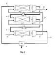
- the gas to be treated arriving via the conduit 11 flows successively into the contactor C4, then C5, then C6.
- the absorbent solution arriving via line 17 flows successively into contactor C6, then C5 then C4.
- the gas and the liquid circulate in co-current, that is to say that they cross the contactor, in the same direction and in the same direction.
- the contactors C4, C5 and C6 are arranged horizontally and the gaseous and liquid phases pass through the contactors in the same horizontal direction.
- the contactors C4, C5 and C6 are provided with contacting elements, for example structured packings, for example structured packings marketed under the trademark BX or Mellapak produced by Sulzer Chemtech or marketed under the brand B1 produced by Montz. , and preferably static mixers which accept higher pressure losses, such as those mentioned in the document " Hydrodynamics and mass transfer in gas-liquid flow through static mixers, Heyouni et al., 2002, Eng Eng., Sci., 57, 3325-3333 .
- the gas to be treated arriving via line 11 is brought into contact with the liquid absorbent solution arriving via line 12 in contactor C4.
- the absorbent solution 12 comes from the contactor C5.
- the gas and the liquid circulate in C4 through a co-current contacting element and in the same horizontal direction.
- the liquid absorbent solution captures the acidic compounds, in particular CO 2 and / or H 2 S contained in the gas.
- the gas is separated from the liquid using the separator S1.
- S1 may be a separate device or included in C4.
- the liquid solution loaded with acidic compounds is removed from S1 via line 13.
- the gas depleted of acidic compounds is removed from S1 via line 14 to be introduced into C5.
- the gas arriving via line 14 is brought into contact with the liquid absorbent solution arriving via line 15 in contactor C5.
- the liquid absorbent solution 15 comes from the contactor C6.
- the gas and the liquid circulate in C5 through a co-current contacting element and in the same horizontal direction.
- the liquid absorbent solution picks up the acid compounds, in particular CO 2 and / or H 2 S contained in the gas.
- the gas is separated from the liquid using separator S2.
- S2 may be a separate device or included in C5.
- the liquid solution loaded with acidic compounds is removed from S2 via line 12 to be introduced into contactor C4.
- the gas depleted of acidic compounds is removed from S2 through line 16 to be introduced into C6.
- the gas arriving via line 16 is brought into contact with the liquid absorbent solution arriving via line 17 in contactor C6.
- the gas and the liquid circulate in C6 through a cocurrent contacting element and in the same horizontal direction.
- the liquid absorbent solution captures acidic compounds, in particular CO 2 and / or H 2 S contained in the gas.
- the gas is separated from the liquid using separator S3.
- S3 can be a separate device or included in C6.
- the liquid solution loaded with acidic compounds is removed from C6 through line 15 to be introduced into contactor C6.
- the gas depleted of acidic compounds is removed from C6 via line 18.
- the absorbent solution discharged from S1 through the conduit 13 is introduced into the regeneration section RE2 to be regenerated.
- the absorbent solution can be regenerated by being expanded and / or heated to release the acidic compounds in gaseous form.
- the acidic gaseous compounds are discharged through line 19.
- the regenerated absorbent solution is removed from RE2 via line 17 to be introduced into contactor C6.
- At least one of the heat exchangers E3 and E4 respectively disposed on the conduits 12 and 15 can be used to cool the absorbent solution or in the separation zones S1, S2, S3.
- the process according to figure 2 to capture CO 2 and / or H 2 S contained in a natural gas.
- the use of horizontal contactors operating at co-current makes it possible to circulate the gas and the liquid in hydrodynamic regimes very favorable to the transfer as in the case of a highly dispersed bubble flow, as shown in the document " Hydrodynamics and mass transfer in gas-liquid flow through static mixers, Heyouni et al., 2002, Eng Eng., Sci., 57, 3325-3333 .
- This mode of implementation generates more pressure drop and is therefore well suited to the problem of treating natural gas under pressure.
- it is less sensitive to movement than a film flow and can be interesting in the case of gas washing on platform at sea subjected to pitching and rolling.
- the implementation of the process according to figure 2 can be achieved by varying the number of contactors used, for example with two or three contactors, or with four or more contactors.
- the Figures 3 and 4 propose to recycle liquid and / or gas, from the output to the input of a contactor.
- the recycle can be implemented on one or more co-current contactors of the method according to the invention.
- recycles can be implemented in the case of vertical contactors described with reference to the figure 1 or in the case of horizontal contactors described with reference to the figure 2 .
- the absorbent solution 20 is contacted in the contactor C with the gas to be treated arriving via the conduit 21. After passing through the contactor C, the absorbent solution is discharged through the conduit 22 and the gas through the conduit 23.
- a portion of the liquid 22 may be circulated, or alternatively a portion of the gas 23 or alternatively a portion of the liquid 22 and a portion of the gas 23, from the outlet to the inlet of the contactor C.
- a portion of the liquid 22 is recycled into the contactor C.
- the liquid absorbent solution 22 is pumped by the pump P and then separated into two liquid fractions, for example by the valves V3 and V4.
- a liquid fraction is evacuated via line 26 either to supply another contactor or to supply the regenerator.
- the other liquid fraction is recycled via the conduit 27 to be introduced again at the inlet of the contactor C, for example by being mixed with the liquid flowing in the conduit 20.
- the gas 23 is divided into two gaseous fractions, for example by means of the valves V1 and V2.
- a gaseous fraction is discharged through the conduit 25.
- Another gaseous fraction is recycled via the conduit 24 to be introduced at the inlet of the contactor C, for example by being mixed with the gas flowing in the conduit 21.
- the gaseous fraction 24 can be compressed by the compressor K.
- the two recycle conduits 24 are used. 27.
- the absorbent solution 30 is contacted in the contactor C with the gas to be treated arriving via the conduit 31.
- the mixture of absorbent solution and gas is discharged through the conduit 32.
- the gas mixture and liquid 32 is divided into two fractions, for example by means of valves V5 and V6.
- a fraction of the mixture of gas and liquid is recycled via line 34 to be introduced at the inlet of contactor C.
- the fraction of the mixture of gas and liquid 34 is compressed. by the multiphase pump PP before being introduced into C.
- the other fraction of mixture of gas and liquid is introduced into the separator of gas and liquid S to produce a liquid absorbent solution discharged through line 36 and a gaseous fraction evacuated via line 35.
- the results presented in Table 1 below show the characteristics and sizing of various processes to decarbonate combustion fumes from a 630 MWe coal-fired power plant.
- the fumes to be treated have a flow rate of 1 750 000 Nm 3 / h with a composition of 13.2% volume of CO 2 .
- CO 2 capture processes with a capture rate of 90% of the CO 2 contained in the fumes are carried out thanks to the circulation of a flow rate of 8300 m 3 / h of absorbent solution composed of an aqueous solution of MEA at 30% by weight, having a respective input and output loading rate of 0.24 and 0.47.
- a case of implementation according to the prior art is compared with two cases of implementation according to the present invention. In all cases, the diameter of the columns is fixed constant and equal to 8 m.
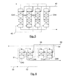
- the stream of fumes to be treated 40 is divided into four to supply each of the four columns CA1, CA2, CA3 and CA4, inducing a gas velocity of 2.4 m / s in the columns.
- the columns are equipped with Mellapak 250.Y structured lining developing a geometric area of 250 m 2 / m 3 .
- the wetting efficiency is 80% which corresponds to an effective area, ae, of 200 m 2 / m 3 .
- the absorbent solution arriving via line 41 is split into four fractions, each supplying one of the columns CA1, CA2, CA3 and CA4.
- the required height for the contact zone in columns CA1 to CA4 is 18m, ie a total packing volume of nearly 3600 m 3 .
- This height is determined via the use of an absorber model integrating kinetics and thermodynamics models specific to a 30 wt% aqueous MEA solution and mass transfer models specific to the Mellapak 250.Y structured packing, which Thus, it is possible to calculate the reaction rates of CO 2 with the amine, the liquid-vapor equilibria and the reactive transfer.
- a first case of implementation of the method according to the invention is shown schematically by the figure 6 .
- a much more efficient packing is used which develops an effective area of 500 m 2 / m 3 while reducing the total passage section.
- the gas stream 50 is divided into two gas fractions 51 and 52 which are contacted cocurrently with an absorbent solution successively in two contactors.
- the absorbent solution arriving via line 53 is also divided into two liquid fractions 54 and 55 which are respectively contacted cocurrently with the gaseous fractions in two co-current contactors.
- the gaseous fraction 51, respectively 52 is contacted cocurrently in CA5 then CA6, respectively CA7 then CA8, with the liquid fraction 55, respectively 54.
- the height of the contactors required to achieve the same performance as those of case 1 according to the prior art is only 5.9 m, which induces a packing volume of nearly 1200 m 3 , or a reduction of almost 70% in the size of the installations.
- a second case of implementation of the method according to the invention is shown schematically by the figure 1 , in which three contactors operating at co-current and without division of the flue gas stream to be treated are used.
- contactors C1, C2 and C3 are equipped with contactors which develop an effective area, ae, of 650 m 2 / m 3 .
- This high value is obtained on the one hand because of the use of highly efficient static mixers and on the other hand by the high speeds of liquid and gas generating a large turbulence favorable to mass transfer and the creation of area interfacial.
- the gas circulation speed is increased to 9.7 m / s through the contactors C1, C2 and C3.
- the method according to the prior art requires that the flow of fumes to be treated is subdivided into several streams. , processed in parallel in dedicated columns. Operating in co-current mode according to our invention and thus to be able to pass more flow in a single column avoids or limits this subdivision.
- the scheme according to the invention makes it possible to reduce the capex (investment costs related to the number and size of the columns).
Landscapes
- Chemical & Material Sciences (AREA)
- Oil, Petroleum & Natural Gas (AREA)
- Chemical Kinetics & Catalysis (AREA)
- Engineering & Computer Science (AREA)
- General Chemical & Material Sciences (AREA)
- Organic Chemistry (AREA)
- Analytical Chemistry (AREA)
- Gas Separation By Absorption (AREA)
- Treating Waste Gases (AREA)
Applications Claiming Priority (1)
| Application Number | Priority Date | Filing Date | Title |
|---|---|---|---|
| FR1102030A FR2977168B1 (fr) | 2011-06-29 | 2011-06-29 | Procede de desacidification d'un gaz avec plusieurs etapes de mise en contact a co-courant avec une solution absorbante |
Publications (1)
| Publication Number | Publication Date |
|---|---|
| EP2540376A1 true EP2540376A1 (de) | 2013-01-02 |
Family
ID=46298320
Family Applications (1)
| Application Number | Title | Priority Date | Filing Date |
|---|---|---|---|
| EP12290193A Withdrawn EP2540376A1 (de) | 2011-06-29 | 2012-06-08 | Entsäuerungsverfahren eines Gases mit mehreren Etappen der Gleichstromkontaktherstellung mit einer absorbierenden Lösung |
Country Status (2)
| Country | Link |
|---|---|
| EP (1) | EP2540376A1 (de) |
| FR (1) | FR2977168B1 (de) |
Cited By (3)
| Publication number | Priority date | Publication date | Assignee | Title |
|---|---|---|---|---|
| CN105056709A (zh) * | 2015-07-30 | 2015-11-18 | 江苏金曼科技有限责任公司 | 一种尾气处理方法 |
| US9334455B2 (en) | 2013-06-28 | 2016-05-10 | Uop Llc | Methods and apparatuses for enhanced absorption of acid gas components from sour feed gas |
| US11413571B2 (en) * | 2018-08-22 | 2022-08-16 | Exxonmobil Upstream Research Company | Removing impurities from a gas stream |
Citations (12)
| Publication number | Priority date | Publication date | Assignee | Title |
|---|---|---|---|---|
| FR1603140A (de) * | 1968-07-10 | 1971-03-22 | ||
| US4296050A (en) | 1977-05-12 | 1981-10-20 | Sulzer Brothers Ltd. | Packing element for an exchange column |
| FR2486512A1 (fr) * | 1980-07-09 | 1982-01-15 | Inst Francais Du Petrole | Procede perfectionne d'epuration de gaz contenant du sulfure d'hydrogene et du dioxyde de carbone et appareillage utilise a cet effet |
| EP0191985A2 (de) * | 1984-12-27 | 1986-08-27 | Imperial Chemical Industries Plc | Behandlung von Gasmischungen |
| US4741888A (en) | 1986-12-30 | 1988-05-03 | Shell Oil Company | H2 S removal from gas streams |
| EP0301623A1 (de) * | 1987-07-14 | 1989-02-01 | N.V. Nederlandse Gasunie | Verfahren zur Abtrennung gasförmiger Komponenten aus einem Gasstrom |
| US5439509A (en) * | 1991-01-22 | 1995-08-08 | Turbotak Inc. | Stripping method and apparatus |
| US6458188B1 (en) * | 2000-07-14 | 2002-10-01 | Timothy D. Mace | Method and means for air filtration |
| EP1294473B1 (de) * | 2000-06-29 | 2006-02-15 | Statoil ASA | Vorrichtung und verfahren zum mischen von fluiden |
| WO2006114502A1 (fr) * | 2005-04-25 | 2006-11-02 | Verite | Reacteur chimique et/ou biologique de grande dimension pour contact entre deux fluides, et installation de traitement comprenant un tel reacteur |
| WO2010044956A1 (en) * | 2008-10-14 | 2010-04-22 | Exxonmobil Upstream Research Company | Removal of acid gases from a gas stream |
| WO2011109359A1 (en) * | 2010-03-02 | 2011-09-09 | Exxonmobil Research And Engineering Company | Systems and methods for acid gas removal |
-
2011
- 2011-06-29 FR FR1102030A patent/FR2977168B1/fr not_active Expired - Fee Related
-
2012
- 2012-06-08 EP EP12290193A patent/EP2540376A1/de not_active Withdrawn
Patent Citations (13)
| Publication number | Priority date | Publication date | Assignee | Title |
|---|---|---|---|---|
| FR1603140A (de) * | 1968-07-10 | 1971-03-22 | ||
| US4296050B1 (en) | 1977-05-12 | 1996-04-23 | Sulzer Bros | Packing element for an exchange column |
| US4296050A (en) | 1977-05-12 | 1981-10-20 | Sulzer Brothers Ltd. | Packing element for an exchange column |
| FR2486512A1 (fr) * | 1980-07-09 | 1982-01-15 | Inst Francais Du Petrole | Procede perfectionne d'epuration de gaz contenant du sulfure d'hydrogene et du dioxyde de carbone et appareillage utilise a cet effet |
| EP0191985A2 (de) * | 1984-12-27 | 1986-08-27 | Imperial Chemical Industries Plc | Behandlung von Gasmischungen |
| US4741888A (en) | 1986-12-30 | 1988-05-03 | Shell Oil Company | H2 S removal from gas streams |
| EP0301623A1 (de) * | 1987-07-14 | 1989-02-01 | N.V. Nederlandse Gasunie | Verfahren zur Abtrennung gasförmiger Komponenten aus einem Gasstrom |
| US5439509A (en) * | 1991-01-22 | 1995-08-08 | Turbotak Inc. | Stripping method and apparatus |
| EP1294473B1 (de) * | 2000-06-29 | 2006-02-15 | Statoil ASA | Vorrichtung und verfahren zum mischen von fluiden |
| US6458188B1 (en) * | 2000-07-14 | 2002-10-01 | Timothy D. Mace | Method and means for air filtration |
| WO2006114502A1 (fr) * | 2005-04-25 | 2006-11-02 | Verite | Reacteur chimique et/ou biologique de grande dimension pour contact entre deux fluides, et installation de traitement comprenant un tel reacteur |
| WO2010044956A1 (en) * | 2008-10-14 | 2010-04-22 | Exxonmobil Upstream Research Company | Removal of acid gases from a gas stream |
| WO2011109359A1 (en) * | 2010-03-02 | 2011-09-09 | Exxonmobil Research And Engineering Company | Systems and methods for acid gas removal |
Non-Patent Citations (1)
| Title |
|---|
| HEYOUNI ET AL.: "Hydrodynamics and mass transfer in gas-liquid flow through static mixers", CHEM. ENG. SCI., vol. 57, 2002, pages 3325 - 3333 |
Cited By (3)
| Publication number | Priority date | Publication date | Assignee | Title |
|---|---|---|---|---|
| US9334455B2 (en) | 2013-06-28 | 2016-05-10 | Uop Llc | Methods and apparatuses for enhanced absorption of acid gas components from sour feed gas |
| CN105056709A (zh) * | 2015-07-30 | 2015-11-18 | 江苏金曼科技有限责任公司 | 一种尾气处理方法 |
| US11413571B2 (en) * | 2018-08-22 | 2022-08-16 | Exxonmobil Upstream Research Company | Removing impurities from a gas stream |
Also Published As
| Publication number | Publication date |
|---|---|
| FR2977168A1 (fr) | 2013-01-04 |
| FR2977168B1 (fr) | 2015-07-24 |
Similar Documents
| Publication | Publication Date | Title |
|---|---|---|
| JP6818760B2 (ja) | コンパクトな海中脱水 | |
| EP3017857B1 (de) | Entsäuerungsverfahren von gashaltigen abwässern mit hilfe einer absorbierenden lösung mit dampfeinspritzung in die regenerierte absorbierende lösung, und vorrichtung für die umsetzung dieses verfahrens | |
| EP2193833B1 (de) | Entsäuerungsverfahren eines Gases durch absorbierende Lösung mit Entmischung bei der Aufbereitung | |
| JP6952807B2 (ja) | 硫黄含有化合物を捕捉するための小型接触システム及び方法 | |
| KR20150110737A (ko) | 가스 스트림과 액체 스트림의 접촉 | |
| WO2010012883A2 (fr) | Solution absorbante a base de n,n,n',n'-tétraméthylhexane- 1,6-diamine et d'une amine particuliere comportant des fonctions amine primaire ou secondaire et procédé d'elimination de composes acides d'un effluent gazeux | |
| WO2010150227A1 (fr) | Procede de traitement de gaz acides | |
| AU2010295593B2 (en) | High pressure high CO2 removal configurations and methods | |
| US11413571B2 (en) | Removing impurities from a gas stream | |
| FR2938454A1 (fr) | Procede de desacidification d'un gaz par une solution absorbante aux amines, avec section de lavage a l'eau | |
| FR2760653A1 (fr) | Procede de desacidification avec production de gaz acides en phase liquide | |
| CA3027775A1 (fr) | Plateau pour colonne d'echange comprenant des cheminees de gaz surmontees de chapeaux au profil aerodynamique | |
| FR2977168A1 (fr) | Procede de desacidification d'un gaz avec plusieurs etapes de mise en contact a co-courant avec une solution absorbante | |
| WO2018114696A1 (fr) | Colonne d'echange de matiere et/ou de chaleur entre un gaz et un liquide avec moyens de recirculation du liquide et son utilisation | |
| WO2022136742A1 (fr) | Procede de capture d'une molecule d'interet et syteme de capture associe | |
| FR2958180A1 (fr) | Procede de desacidification d'un gaz par une solution absorbante, avec section de lavage acide | |
| RU2627847C2 (ru) | Способ и колонна абсорбционной очистки газов от нежелательных примесей | |
| CA1097485A (fr) | Procede d'enrichissement en h2s des gas acides | |
| FR2896509A1 (fr) | Procede de capture des mercaptans contenus dans un gaz naturel par concentration. | |
| FR2961115A1 (fr) | Procede de desacidification d'un gaz par une solution absorbante dans deux sections d'absorption agencees dans une colonne. | |
| WO2013064755A1 (fr) | Procédé de désacidification d'un gaz avec plusieurs étapes de mise en contact à courant croisé avec une solution absorbante | |
| CA1339242C (fr) | Procede et dispositif pour l'elimination de l'h s present a faible concentration dans un gaz renfermant egalement une quantite importante de vapeur d'eau | |
| US10315154B2 (en) | Method for the recovery of carbon dioxide from an absorbent with reduced supply of stripping steam | |
| FR2979550A1 (fr) | Dispositif et procede de desacidification d'un gaz avec section pour limiter les entrainements de gaz dans la solution absorbante | |
| OA20253A (fr) | Colonne d'échange de matière et/ou de chaleur entre un gaz et un liquide avec moyens de recirculation du liquide et son utilisation |
Legal Events
| Date | Code | Title | Description |
|---|---|---|---|
| PUAI | Public reference made under article 153(3) epc to a published international application that has entered the european phase |
Free format text: ORIGINAL CODE: 0009012 |
|
| AK | Designated contracting states |
Kind code of ref document: A1 Designated state(s): AL AT BE BG CH CY CZ DE DK EE ES FI FR GB GR HR HU IE IS IT LI LT LU LV MC MK MT NL NO PL PT RO RS SE SI SK SM TR |
|
| AX | Request for extension of the european patent |
Extension state: BA ME |
|
| 17P | Request for examination filed |
Effective date: 20130702 |
|
| RBV | Designated contracting states (corrected) |
Designated state(s): AL AT BE BG CH CY CZ DE DK EE ES FI FR GB GR HR HU IE IS IT LI LT LU LV MC MK MT NL NO PL PT RO RS SE SI SK SM TR |
|
| 17Q | First examination report despatched |
Effective date: 20170818 |
|
| RAP1 | Party data changed (applicant data changed or rights of an application transferred) |
Owner name: IFP ENERGIES NOUVELLES |
|
| GRAP | Despatch of communication of intention to grant a patent |
Free format text: ORIGINAL CODE: EPIDOSNIGR1 |
|
| RIC1 | Information provided on ipc code assigned before grant |
Ipc: B01D 53/18 20060101ALI20190625BHEP Ipc: C10L 3/10 20060101ALI20190625BHEP Ipc: B01D 53/14 20060101AFI20190625BHEP |
|
| INTG | Intention to grant announced |
Effective date: 20190726 |
|
| STAA | Information on the status of an ep patent application or granted ep patent |
Free format text: STATUS: THE APPLICATION IS DEEMED TO BE WITHDRAWN |
|
| 18D | Application deemed to be withdrawn |
Effective date: 20191206 |