EP2540395A2 - Appareil et procédé destinés à distribuer des échantillons liquides dans des petits volumes - Google Patents
Appareil et procédé destinés à distribuer des échantillons liquides dans des petits volumes Download PDFInfo
- Publication number
- EP2540395A2 EP2540395A2 EP11747771A EP11747771A EP2540395A2 EP 2540395 A2 EP2540395 A2 EP 2540395A2 EP 11747771 A EP11747771 A EP 11747771A EP 11747771 A EP11747771 A EP 11747771A EP 2540395 A2 EP2540395 A2 EP 2540395A2
- Authority
- EP
- European Patent Office
- Prior art keywords
- reservoirs
- duct
- ducts
- communicating
- sample liquid
- Prior art date
- Legal status (The legal status is an assumption and is not a legal conclusion. Google has not performed a legal analysis and makes no representation as to the accuracy of the status listed.)
- Withdrawn
Links
- 239000007788 liquid Substances 0.000 title claims abstract description 83
- 238000000034 method Methods 0.000 title claims abstract description 12
- 239000000463 material Substances 0.000 claims abstract description 7
- 238000004519 manufacturing process Methods 0.000 claims abstract description 3
- -1 polyethylene terephthalate Polymers 0.000 claims description 12
- 230000000694 effects Effects 0.000 claims description 11
- 230000005484 gravity Effects 0.000 claims description 11
- 239000004698 Polyethylene Substances 0.000 claims description 8
- 239000004743 Polypropylene Substances 0.000 claims description 8
- 229920000573 polyethylene Polymers 0.000 claims description 8
- 229920000139 polyethylene terephthalate Polymers 0.000 claims description 8
- 239000005020 polyethylene terephthalate Substances 0.000 claims description 8
- 229920001155 polypropylene Polymers 0.000 claims description 8
- 230000000295 complement effect Effects 0.000 claims description 5
- 239000005038 ethylene vinyl acetate Substances 0.000 claims description 4
- 229920000728 polyester Polymers 0.000 claims description 4
- 239000004800 polyvinyl chloride Substances 0.000 claims description 4
- 229920001169 thermoplastic Polymers 0.000 claims description 4
- 229920001187 thermosetting polymer Polymers 0.000 claims description 4
- 239000004416 thermosoftening plastic Substances 0.000 claims description 4
- 239000000853 adhesive Substances 0.000 claims description 3
- 230000001070 adhesive effect Effects 0.000 claims description 3
- 238000000926 separation method Methods 0.000 description 9
- 241000894006 Bacteria Species 0.000 description 5
- QVGXLLKOCUKJST-UHFFFAOYSA-N atomic oxygen Chemical compound [O] QVGXLLKOCUKJST-UHFFFAOYSA-N 0.000 description 5
- 238000013461 design Methods 0.000 description 5
- 229910052760 oxygen Inorganic materials 0.000 description 5
- 239000001301 oxygen Substances 0.000 description 5
- 230000004060 metabolic process Effects 0.000 description 4
- 244000005700 microbiome Species 0.000 description 4
- 230000000903 blocking effect Effects 0.000 description 3
- 238000012360 testing method Methods 0.000 description 3
- 230000001580 bacterial effect Effects 0.000 description 2
- 239000003153 chemical reaction reagent Substances 0.000 description 2
- 238000011161 development Methods 0.000 description 2
- 238000011002 quantification Methods 0.000 description 2
- 230000000630 rising effect Effects 0.000 description 2
- XLYOFNOQVPJJNP-UHFFFAOYSA-N water Substances O XLYOFNOQVPJJNP-UHFFFAOYSA-N 0.000 description 2
- 230000001174 ascending effect Effects 0.000 description 1
- 238000010790 dilution Methods 0.000 description 1
- 239000012895 dilution Substances 0.000 description 1
- 239000003814 drug Substances 0.000 description 1
- 238000000855 fermentation Methods 0.000 description 1
- 230000004151 fermentation Effects 0.000 description 1
- 238000002955 isolation Methods 0.000 description 1
- 238000005374 membrane filtration Methods 0.000 description 1
- 230000002503 metabolic effect Effects 0.000 description 1
- 239000000203 mixture Substances 0.000 description 1
- 230000008506 pathogenesis Effects 0.000 description 1
- 238000013139 quantization Methods 0.000 description 1
- 230000029058 respiratory gaseous exchange Effects 0.000 description 1
- 238000007789 sealing Methods 0.000 description 1
- 238000010561 standard procedure Methods 0.000 description 1
- 239000002351 wastewater Substances 0.000 description 1
Images



Classifications
-
- B—PERFORMING OPERATIONS; TRANSPORTING
- B01—PHYSICAL OR CHEMICAL PROCESSES OR APPARATUS IN GENERAL
- B01J—CHEMICAL OR PHYSICAL PROCESSES, e.g. CATALYSIS OR COLLOID CHEMISTRY; THEIR RELEVANT APPARATUS
- B01J4/00—Feed or outlet devices; Feed or outlet control devices
- B01J4/02—Feed or outlet devices; Feed or outlet control devices for feeding measured, i.e. prescribed quantities of reagents
-
- B—PERFORMING OPERATIONS; TRANSPORTING
- B01—PHYSICAL OR CHEMICAL PROCESSES OR APPARATUS IN GENERAL
- B01L—CHEMICAL OR PHYSICAL LABORATORY APPARATUS FOR GENERAL USE
- B01L3/00—Containers or dishes for laboratory use, e.g. laboratory glassware; Droppers
- B01L3/50—Containers for the purpose of retaining a material to be analysed, e.g. test tubes
- B01L3/502—Containers for the purpose of retaining a material to be analysed, e.g. test tubes with fluid transport, e.g. in multi-compartment structures
- B01L3/5025—Containers for the purpose of retaining a material to be analysed, e.g. test tubes with fluid transport, e.g. in multi-compartment structures for parallel transport of multiple samples
-
- B—PERFORMING OPERATIONS; TRANSPORTING
- B01—PHYSICAL OR CHEMICAL PROCESSES OR APPARATUS IN GENERAL
- B01L—CHEMICAL OR PHYSICAL LABORATORY APPARATUS FOR GENERAL USE
- B01L3/00—Containers or dishes for laboratory use, e.g. laboratory glassware; Droppers
-
- B—PERFORMING OPERATIONS; TRANSPORTING
- B01—PHYSICAL OR CHEMICAL PROCESSES OR APPARATUS IN GENERAL
- B01L—CHEMICAL OR PHYSICAL LABORATORY APPARATUS FOR GENERAL USE
- B01L3/00—Containers or dishes for laboratory use, e.g. laboratory glassware; Droppers
- B01L3/50—Containers for the purpose of retaining a material to be analysed, e.g. test tubes
- B01L3/502—Containers for the purpose of retaining a material to be analysed, e.g. test tubes with fluid transport, e.g. in multi-compartment structures
- B01L3/5027—Containers for the purpose of retaining a material to be analysed, e.g. test tubes with fluid transport, e.g. in multi-compartment structures by integrated microfluidic structures, i.e. dimensions of channels and chambers are such that surface tension forces are important, e.g. lab-on-a-chip
-
- B—PERFORMING OPERATIONS; TRANSPORTING
- B01—PHYSICAL OR CHEMICAL PROCESSES OR APPARATUS IN GENERAL
- B01L—CHEMICAL OR PHYSICAL LABORATORY APPARATUS FOR GENERAL USE
- B01L2200/00—Solutions for specific problems relating to chemical or physical laboratory apparatus
- B01L2200/06—Fluid handling related problems
- B01L2200/0605—Metering of fluids
-
- B—PERFORMING OPERATIONS; TRANSPORTING
- B01—PHYSICAL OR CHEMICAL PROCESSES OR APPARATUS IN GENERAL
- B01L—CHEMICAL OR PHYSICAL LABORATORY APPARATUS FOR GENERAL USE
- B01L2200/00—Solutions for specific problems relating to chemical or physical laboratory apparatus
- B01L2200/06—Fluid handling related problems
- B01L2200/0642—Filling fluids into wells by specific techniques
-
- B—PERFORMING OPERATIONS; TRANSPORTING
- B01—PHYSICAL OR CHEMICAL PROCESSES OR APPARATUS IN GENERAL
- B01L—CHEMICAL OR PHYSICAL LABORATORY APPARATUS FOR GENERAL USE
- B01L2300/00—Additional constructional details
- B01L2300/08—Geometry, shape and general structure
- B01L2300/0809—Geometry, shape and general structure rectangular shaped
- B01L2300/0829—Multi-well plates; Microtitration plates
-
- B—PERFORMING OPERATIONS; TRANSPORTING
- B01—PHYSICAL OR CHEMICAL PROCESSES OR APPARATUS IN GENERAL
- B01L—CHEMICAL OR PHYSICAL LABORATORY APPARATUS FOR GENERAL USE
- B01L2300/00—Additional constructional details
- B01L2300/08—Geometry, shape and general structure
- B01L2300/0861—Configuration of multiple channels and/or chambers in a single devices
- B01L2300/0864—Configuration of multiple channels and/or chambers in a single devices comprising only one inlet and multiple receiving wells, e.g. for separation, splitting
-
- B—PERFORMING OPERATIONS; TRANSPORTING
- B01—PHYSICAL OR CHEMICAL PROCESSES OR APPARATUS IN GENERAL
- B01L—CHEMICAL OR PHYSICAL LABORATORY APPARATUS FOR GENERAL USE
- B01L2400/00—Moving or stopping fluids
- B01L2400/04—Moving fluids with specific forces or mechanical means
- B01L2400/0403—Moving fluids with specific forces or mechanical means specific forces
- B01L2400/0457—Moving fluids with specific forces or mechanical means specific forces passive flow or gravitation
-
- B—PERFORMING OPERATIONS; TRANSPORTING
- B01—PHYSICAL OR CHEMICAL PROCESSES OR APPARATUS IN GENERAL
- B01L—CHEMICAL OR PHYSICAL LABORATORY APPARATUS FOR GENERAL USE
- B01L2400/00—Moving or stopping fluids
- B01L2400/06—Valves, specific forms thereof
- B01L2400/0633—Valves, specific forms thereof with moving parts
- B01L2400/0655—Valves, specific forms thereof with moving parts pinch valves
-
- Y—GENERAL TAGGING OF NEW TECHNOLOGICAL DEVELOPMENTS; GENERAL TAGGING OF CROSS-SECTIONAL TECHNOLOGIES SPANNING OVER SEVERAL SECTIONS OF THE IPC; TECHNICAL SUBJECTS COVERED BY FORMER USPC CROSS-REFERENCE ART COLLECTIONS [XRACs] AND DIGESTS
- Y10—TECHNICAL SUBJECTS COVERED BY FORMER USPC
- Y10T—TECHNICAL SUBJECTS COVERED BY FORMER US CLASSIFICATION
- Y10T156/00—Adhesive bonding and miscellaneous chemical manufacture
- Y10T156/10—Methods of surface bonding and/or assembly therefor
- Y10T156/1052—Methods of surface bonding and/or assembly therefor with cutting, punching, tearing or severing
Definitions
- the invention consists of a preformed rigid duct of impermeable material, with one inlet and one or more outlets wherein automatic distribution of sample liquids in reservoirs or compartments preformed in the same duct is achieved by the effects of gravity and air movement.
- the duct dimensions vary along the same, forming communicating ducts, reservoirs and sometimes bifurcations.
- the duct is located so that the inlet and the outlet or outlets is/are at an upper level and below thereof, two or more reservoirs which are identical or different to each other can be located:
- the dimensions of the reservoirs are calculated based on the total number of parts in which the sample is desired to be divided, the total sample volume and amount of air and sample liquid which is desired to be left in each of the reservoirs and also the desired geometric shape to be used for each reservoir wherein these may be identical or different from each other.
- the height level on which said communicating ducts enter and exit in the reservoirs is determined by the required proportion or percentage of sample liquid and of air that is desired to remain in each of them, and even leave it without air. This level may be equal in all the reservoirs or different among them, depending on the needs of the user and is calculated taking into consideration the apparatus in upright position.
- the communicating ducts may be located always on the same side in all the reservoirs so that when the apparatus is leant to the opposite side from that on which the ducts are located, the sample liquid is evacuated by effects of gravity from the communicating ducts and housed into the reservoirs, the sample liquid, besides being divided, is completely separated and left independent.
- the most commonly used methods for quantification of bacteria and other microorganisms in the water are those of Membrane filtration and the Most Probable Number (MPN) method.
- the first is somewhat more limited than the latter because of its quantifying difficulty when the number of colonies is very high.
- the NMP procedure is based on a statistical estimate of the number of bacteria per unit volume and is determined by the number of positive results of a series of incubated tubes or reservoirs. The greater the number of incubated reservoirs, the higher is the accuracy of the obtained results. Also, when bacteria counts are very high, this method allows to perform dilutions in order to find effective readings that allow to get a clear idea of the bacterial density of the sample liquid.
- a simple and rapid method for separating the sample liquid into many small, homogeneous portions, as well as the ability of having or not, as the case may be, air in each of the culture reservoirs or compartments is useful for optimal results.
- the bacterial density estimation by the NMP method can be done in two ways, one being by determining multiple tubes as described in "Standard Methods for the Examination of Water and Wastewater” using test tubes performing the manual separation of the sample liquid through pipettes or similar devices and also using the method described in Patents Nos. US 5,518,892 , US 5,620,895 , US 5,753,456 .
- an apparatus is used for separation of the sample consisting of a bag in which the sample liquid is divided by the mechanical action of rollers that at the same time provide the necessary heat for adhering a film to the rigid side of the bag, thus achieving complete separation of the sample.
- This option does not allow the option of leaving a specific volume of air in each of the aliquots and also requires special equipment for separation and division.
- the apparatus according to this patent contains the following differences:
- Another advantage is that, for the case of the reservoirs containing sufficient air and further when the design of the reservoirs is appropriate, the liquid in each reservoir is separated from the rest by simply leaning or rotating the apparatus.
- the separation between the compartments could also be obtained by simply sealing the communicating ducts that the reservoirs have with each other by action of heat and pressure applied at specific points.
- the invention consists of a preformed and rigid duct of impermeable material, with one inlet and one or more outlets wherein automatic distribution of sample liquids in reservoirs or compartments preformed in the same duct is achieved by the effects of gravity and air movement.
- the duct dimensions vary along the same, forming communicating ducts, bifurcations and reservoirs, which are located so as to allow a controlled flow of air and housing of the sample liquid in the reservoirs formed therein.
- the duct is located so that the inlet and the outlet or outlets is/are at an upper level and below thereof, two or more reservoirs which are identical or different to each other can be located:
- Two or more series of reservoirs can be used in the same apparatus.
- the dimensions of the reservoirs are calculated based on the total number of parts in which the sample is desired to be divided, the total sample volume and the amount of air and sample liquid which is desired to be left in each of the reservoirs and also the desired geometric shape to be used for each reservoir may be identical or different from each other.
- the height level on which said communicating ducts enter and exit in the reservoirs is determined by the required proportion or percentage of sample liquid and of air that is desired to remain in each of them, and even leave it without air. This level may be equal in all the reservoirs or different among them, depending on the needs of the user and is calculated taking into consideration the apparatus in upright position.
- the communicating ducts may be located always on the same side in all the reservoirs so that when the apparatus is leant to the opposite side from that on which the ducts are located, the sample liquid is evacuated by effects of gravity from the communicating ducts and housed into the reservoirs, the sample liquid, besides being divided, is completely separated and left independent.
- the reservoirs must always be located below the level of the inlet to the duct and of the outlet or outlets thereof, regardless of the position.
- the dimensions of the reservoirs and ducts, as well as the location of the inlets and outlets from the communicating ducts to the reservoirs are defined depending on the following variables;
- each reservoir and of the ducts can be adjusted to the dimensions most suitable for the production process, geometric shape or desired design, as long as they have the required volume including the amount of air required for each reservoir and taking into consideration the apparatus in the upright position.
- the sum of the volume of the ducts, reservoirs (whether or not equal to each other), is equal to the total sample volume plus the desired air percentage.
- the height at which the upper part of the communicating ducts of each reservoir is located is determined by obtaining the height level that the sample liquid will cover in each reservoir taking into account the volume of sample liquid contained in the ducts, placing the latter preferably on the same side of the reservoirs in all cases.
- the duct is placed vertically, with the sample liquid inlet on the top part.
- the sample liquid is poured into the duct and by the effects of gravity it is distributed in each of the minor reservoirs through the lower communicating ducts.
- the air contained therein is displaced by the liquid and exits through the ascending communicating ducts, thus allowing the defined filling of each of the reservoirs.
- the width of the reservoirs must be sufficient and proportionally greater than their length, so that only by leaning the apparatus, the communicating ducts are in the upper part thereof, causing the sample liquid located in the ducts to be removed by effect of gravity from the same and to be located in the reservoirs where the final volume of sample liquid from each reservoir does not reach the level at which the communicating ducts are located, thus achieving, apart from the division, the separation of the sample liquid.
- the reservoirs could be isolated definitively by blocking the passage of all the communicating ducts using an apparatus that applies heat and pressure exclusively to specific points of the communicating ducts.
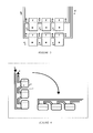
- Example 1 (FIGURE 5) of an apparatus for quantification of aerobic and anaerobic facultative bacteria through the 72 reservoir NMP.
- An example of this apparatus is a duct of a material such as thermoplastic or thermosetting polyvinyl chloride (PVC), polyethylene terephthalate (PET), polyester, ethylene vinyl acetate (EVA), polyethylene (PE), polypropylene (PP) or similar, or a combination of these, transparent, composed of two plates, one of which has a portion of the duct thermoformed with the desired dimensions and shapes and the other complementary plate, attached to the first one, concluding the shape of the duct.
- PVC thermoplastic or thermosetting polyvinyl chloride
- PET polyethylene terephthalate
- EVA ethylene vinyl acetate
- PE polyethylene
- PP polypropylene
- the design of the duct in the thermoformed plate includes: a major reservoir for the distribution of liquid which is on the top part and with a volume of 100 ml and that in turn has an upper opening through which the sample liquid is to be introduced.
- each level has 72 equal reservoirs located at 6 levels, each level with a series of 12 reservoirs.
- Each reservoir has a volume of 1.95 ml and the following dimensions 1 cm x 1.2 cm x 1.625 cm.
- the reservoirs of each level are joined to its neighbor by means of communicating ducts in the form of half-tube with a diameter of 0.7 cm and which are located at a height of 1.15 cm from the bottom of the reservoir, allowing each reservoir to contain a volume of 1.38 ml of sample liquid and an air percentage of 30%.
- the first reservoir of each series is connected via a duct with a diameter of 0.7 cm to one of two vertical ducts with a diameter of 0.7 and which in turn are joined to the major reservoir, the first of these for the first two series and the second one for the remaining.
- a communicating duct exits in the shape of a half-tube and of 0.3 cm in diameter, towards the top part of the plate which allows the exit of excess air thus allowing the flow of sample liquid through the reservoirs of the same level.
- thermoformed plate is joined by means of heat and/or pressure and/or an adhesive to a complementary plate, the two parts being joined together forming a rigid and impermeable duct.
- contour is cut by means of a die cut and the communicating ducts that facilitate the exit of air as well as the entrance of sample liquid to the upper reservoir are opened to the outside. Once finished, it is sterilized for conducting tests such as those of NMP using specific reagents for each microorganism type.
- the apparatus is placed vertically, with the major reservoir and sample liquid inlet on the top part.
- the sample liquid is poured into said reservoir and by the effects of gravity and movement of air it is distributed in each of the minor reservoirs through the communicating ducts.
- the sample liquid in each minor reservoir remains at the bottom allowing the desired percentage of air to remain therein by being above the level at which the communicating ducts are located.
- the excess air contained therein exits through the communicating ducts to the adjacent reservoir and ultimately to the ducts rising on one side of the upper reservoir allowing the distribution of the sample liquid into the minor reservoirs.
- the apparatus only needs to be leant placing the communicating ducts on the top part which will cause the remaining air in each reservoir to isolate the liquid from the same by avoiding contact with the liquid of adjacent reservoirs.
- the reservoirs could be definitively isolated by blocking the passage of all communicating ducts using an apparatus that applies heat and pressure exclusively to specific points of the communicating ducts.
- Example 2 (FIGURE 6) of an apparatus for quantization of aerobic and anaerobic facultative bacteria through the 75 communicated, independent reservoir NMP
- An example of this apparatus is a duct of a material such as thermoplastic or thermosetting polyvinyl chloride (PVC), polyethylene terephthalate (PET), polyester, ethylene vinyl acetate (EVA), polyethylene (PE), polypropylene (PP) or similar, or a combination of these, or even coextruded and mixtures or the like, transparent, composed of two plates, one of which has a portion of the duct thermoformed with the desired dimensions and shapes and the other complementary plate, attached to the first one, concluding the shape of the duct.
- PVC thermoplastic or thermosetting polyvinyl chloride
- PET polyethylene terephthalate
- EVA ethylene vinyl acetate
- PE polyethylene
- PP polypropylene
- the design of the duct in the thermoformed plate includes: a major reservoir for the distribution of the liquid which is on the top part and with a volume of 100 ml and that in turn has an upper opening through which the sample liquid is to be introduced.
- each reservoir has 72 equal reservoirs located in 8 columns, each column with a series of 9 reservoirs and 3 additional reservoirs.
- Each reservoir has a predetermined volume with a specific liquid and air ratio.
- the reservoirs of each level are attached to a contiguous reservoir through communicating ducts that are located at a predetermined height with respect to the lower part of the reservoir which allows each reservoir to contain a specific volume of sample liquid and percentage of air.
- the first reservoir of each series is attached via a duct to the horizontal part of the main distribution duct exiting from the major reservoir.
- a communicating duct exits which is connected to the main air outlet duct and from there to the top part of the apparatus allowing the exit of excess air thereby allowing the flow of sample liquid through the reservoirs.
- thermoformed plate is joined by means of heat and/or pressure and/or an adhesive to a complementary plate, the two parts being joined together forming a rigid and impermeable duct.
- contour is cut by means of a die cut and the entrance through which sample liquid is poured to the upper reservoir and the communicating duct that facilitates the exit of air are opened to the outside. Once finished, it is sterilized for conducting tests such as those of NMP using specific reagents for each microorganism type.
- the apparatus is placed vertically, with the major reservoir and sample liquid inlet at the top.
- the sample liquid is poured into said reservoir and by the effects of gravity and movement of air it is distributed in each of the minor reservoirs in the different levels through the communicating ducts.
- the sample liquid in each minor reservoir remains at the lower part allowing the desired percentage of air to remain therein by being above the level at which the communicating ducts are located.
- the excess air contained therein exits through the communicating ducts to the reservoir located above it and ultimately through the ducts rising to the main air exit duct allowing the distribution of the sample liquid into the minor reservoirs.
- the apparatus only needs to be rotated, placing the communicating ducts on the top part which will cause the sample liquid contained in the communicating ducts between the reservoirs to flow and be deposited in the corresponding compartment leaving said duct free from liquid.
- the sample liquid contained in the main distribution duct is distributed into the three additional reservoirs.
- the apparatus is leant with the reservoir facing down placing the reservoirs on the upper face.
- the reservoirs could be definitively isolated by blocking the passage of all the communicating ducts using an apparatus that applies heat and pressure exclusively to specific points of the communicating ducts.
- the inclination of the apparatus only need to be varied from the vertical when pouring the sample liquid.
Landscapes
- Chemical & Material Sciences (AREA)
- Health & Medical Sciences (AREA)
- Chemical Kinetics & Catalysis (AREA)
- Clinical Laboratory Science (AREA)
- Analytical Chemistry (AREA)
- General Health & Medical Sciences (AREA)
- Hematology (AREA)
- Dispersion Chemistry (AREA)
- Organic Chemistry (AREA)
- Apparatus Associated With Microorganisms And Enzymes (AREA)
- Sampling And Sample Adjustment (AREA)
Applications Claiming Priority (2)
| Application Number | Priority Date | Filing Date | Title |
|---|---|---|---|
| MX2010002036A MX2010002036A (es) | 2010-02-22 | 2010-02-22 | Aparatos y metodo para distribuir liquidos muestra en pequeños volumenes. |
| PCT/MX2011/000032 WO2011105884A2 (fr) | 2010-02-22 | 2011-02-22 | Appareil et procédé destinés à distribuer des échantillons liquides dans des petits volumes |
Publications (1)
| Publication Number | Publication Date |
|---|---|
| EP2540395A2 true EP2540395A2 (fr) | 2013-01-02 |
Family
ID=45492084
Family Applications (1)
| Application Number | Title | Priority Date | Filing Date |
|---|---|---|---|
| EP11747771A Withdrawn EP2540395A2 (fr) | 2010-02-22 | 2011-02-22 | Appareil et procédé destinés à distribuer des échantillons liquides dans des petits volumes |
Country Status (7)
| Country | Link |
|---|---|
| US (1) | US20130059329A1 (fr) |
| EP (1) | EP2540395A2 (fr) |
| JP (1) | JP2013520677A (fr) |
| KR (1) | KR20130121675A (fr) |
| CN (1) | CN103097028A (fr) |
| BR (1) | BR112012021124A2 (fr) |
| MX (1) | MX2010002036A (fr) |
Families Citing this family (4)
| Publication number | Priority date | Publication date | Assignee | Title |
|---|---|---|---|---|
| KR102012315B1 (ko) | 2019-05-08 | 2019-08-28 | 대한민국 | 수질분석용 시료를 균일하게 분배할 수 있는 장치 |
| KR102926717B1 (ko) * | 2023-04-13 | 2026-02-11 | 한국화학연구원 | 초파리 흡입 노출 시스템 |
| WO2024215002A1 (fr) * | 2023-04-13 | 2024-10-17 | 한국화학연구원 | Dispositif expérimental d'exposition par inhalation à des mouches de fruits et système d'exposition par inhalation à des mouches de fruits |
| WO2025168226A1 (fr) * | 2024-02-07 | 2025-08-14 | Vosbio, Inc. | Appareil et procédé de détection |
Family Cites Families (4)
| Publication number | Priority date | Publication date | Assignee | Title |
|---|---|---|---|---|
| US5603351A (en) * | 1995-06-07 | 1997-02-18 | David Sarnoff Research Center, Inc. | Method and system for inhibiting cross-contamination in fluids of combinatorial chemistry device |
| US5609828A (en) * | 1995-05-31 | 1997-03-11 | bio M erieux Vitek, Inc. | Sample card |
| DE10302721A1 (de) * | 2003-01-23 | 2004-08-05 | Steag Microparts Gmbh | Mikrofluidische Anordnung zum Dosieren von Flüssigkeiten |
| CN101194155B (zh) * | 2005-04-09 | 2012-07-18 | 贝林格尔英格海姆米克罗帕茨有限责任公司 | 用于测试样品液的装置和方法 |
-
2010
- 2010-02-22 MX MX2010002036A patent/MX2010002036A/es unknown
-
2011
- 2011-02-22 CN CN2011800202686A patent/CN103097028A/zh active Pending
- 2011-02-22 KR KR1020127024985A patent/KR20130121675A/ko not_active Withdrawn
- 2011-02-22 BR BR112012021124-2A patent/BR112012021124A2/pt not_active IP Right Cessation
- 2011-02-22 EP EP11747771A patent/EP2540395A2/fr not_active Withdrawn
- 2011-02-22 US US13/580,588 patent/US20130059329A1/en not_active Abandoned
- 2011-02-22 JP JP2012554952A patent/JP2013520677A/ja not_active Withdrawn
Non-Patent Citations (1)
| Title |
|---|
| See references of WO2011105884A2 * |
Also Published As
| Publication number | Publication date |
|---|---|
| JP2013520677A (ja) | 2013-06-06 |
| CN103097028A (zh) | 2013-05-08 |
| KR20130121675A (ko) | 2013-11-06 |
| MX2010002036A (es) | 2011-08-31 |
| US20130059329A1 (en) | 2013-03-07 |
| BR112012021124A2 (pt) | 2019-09-24 |
Similar Documents
| Publication | Publication Date | Title |
|---|---|---|
| FI93147C (fi) | Kertakäyttölaite, joka on tarkoitettu käytettäväksi kemiallisissa, immunokemiallisissa ja mikro-organismien analyyseissä | |
| JP3145406B2 (ja) | 液体試料中の生物学的材料の定量化装置および方法 | |
| CN111989157B (zh) | 微流控芯片 | |
| US20130059329A1 (en) | Apparatus and method for distributing liquid samples in small volumes | |
| CN106661524A (zh) | 反应器泡沫传感器系统及使用方法 | |
| JP2012518436A (ja) | マニホールドを備えた細胞培養システム | |
| US3338794A (en) | Culturing anaerobic bacteria | |
| US20080044894A1 (en) | Cellular culture chip device | |
| US20250319465A1 (en) | Incubation well with an unvented gas cavity for use in a microfluidic chip | |
| DE19810499A1 (de) | Mikrotiterplatte | |
| US20130189770A1 (en) | Sample testing device | |
| US20110183408A1 (en) | Reagent cartridge for microorganism detection apparatus | |
| CN206057190U (zh) | 单中心多通道微生物、免疫生化反应检测板 | |
| CN114437916A (zh) | 一种核酸提取装置用流向控制系统 | |
| WO2011105884A2 (fr) | Appareil et procédé destinés à distribuer des échantillons liquides dans des petits volumes | |
| GB2604824A (en) | Disposable urine collection container | |
| TWM597779U (zh) | 共培養裝置 | |
| CN216170135U (zh) | 一种用于医疗分析液体脱气的装置 | |
| GB1572596A (en) | Apparatus and method for innoculation | |
| CN102628760B (zh) | 一种杯形多级线虫分离器 | |
| CN210620806U (zh) | 一种快速加样药敏板 | |
| US20070276289A1 (en) | Self-contained specimen collection and testing device | |
| DK202170546A1 (en) | Device for separating motile cells | |
| CN206033761U (zh) | 单中心多通道组合式细菌药敏检测板 | |
| CN111530515A (zh) | 一种微流控芯片 |
Legal Events
| Date | Code | Title | Description |
|---|---|---|---|
| PUAI | Public reference made under article 153(3) epc to a published international application that has entered the european phase |
Free format text: ORIGINAL CODE: 0009012 |
|
| 17P | Request for examination filed |
Effective date: 20120924 |
|
| AK | Designated contracting states |
Kind code of ref document: A2 Designated state(s): AL AT BE BG CH CY CZ DE DK EE ES FI FR GB GR HR HU IE IS IT LI LT LU LV MC MK MT NL NO PL PT RO RS SE SI SK SM TR |
|
| DAX | Request for extension of the european patent (deleted) | ||
| STAA | Information on the status of an ep patent application or granted ep patent |
Free format text: STATUS: THE APPLICATION IS DEEMED TO BE WITHDRAWN |
|
| 18D | Application deemed to be withdrawn |
Effective date: 20140902 |