EP2540429A1 - Machine de coupe pour panneaux de bois ou similaires - Google Patents
Machine de coupe pour panneaux de bois ou similaires Download PDFInfo
- Publication number
- EP2540429A1 EP2540429A1 EP12174674A EP12174674A EP2540429A1 EP 2540429 A1 EP2540429 A1 EP 2540429A1 EP 12174674 A EP12174674 A EP 12174674A EP 12174674 A EP12174674 A EP 12174674A EP 2540429 A1 EP2540429 A1 EP 2540429A1
- Authority
- EP
- European Patent Office
- Prior art keywords
- slide
- cutting machine
- machine according
- feeding device
- cutting
- Prior art date
- Legal status (The legal status is an assumption and is not a legal conclusion. Google has not performed a legal analysis and makes no representation as to the accuracy of the status listed.)
- Granted
Links
Images




Classifications
-
- B—PERFORMING OPERATIONS; TRANSPORTING
- B27—WORKING OR PRESERVING WOOD OR SIMILAR MATERIAL; NAILING OR STAPLING MACHINES IN GENERAL
- B27B—SAWS FOR WOOD OR SIMILAR MATERIAL; COMPONENTS OR ACCESSORIES THEREFOR
- B27B31/00—Arrangements for conveying, loading, turning, adjusting, or discharging the log or timber, specially designed for saw mills or sawing machines
Definitions
- the present invention relates to a machine for cutting wood panels or alike.
- a cutting machine comprising a supporting structure defining a substantially horizontal supporting surface for at least one wood panel or alike; a cutting station; a feeding unit for feeding the panels along the supporting surface and through the cutting station in a given first direction; and a cutting device mounted in the cutting station and movable in a second direction perpendicular to the first direction to cut the panels.
- the feeding unit comprises a motorized first feeding device movable along the supporting structure to feed at least one first panel through the cutting station, and a motorized second feeding device movable along the supporting structure independently from the first feeding device to feed at least one second panel through the cutting station itself.
- feeding units used to feed the panels along the supporting surface and through the cutting station.
- the first feeding device extends between two side longitudinal members of the supporting structure arranged on opposite sides of the supporting surface in the second direction, and the second feeding device is movable between a resting position, in which the second feeding device is arranged either under the supporting surface or externally to one of the side longitudinal members, and an operating position, in which the second feeding device protrudes over the supporting surface and between the side longitudinal members themselves.
- the two feeding devices are arranged side-by-side and each extend between a respective side longitudinal member and a central longitudinal member mounted between the side longitudinal members.
- the feeding unit is relatively complex, cumbersome and costly, it does not allow to implement the second feeding device in cutting machines designed and marketed with a single feeding device, and always requires both feeding devices to be motorized.
- numeral 1 indicates as a whole a cutting machine for cutting wood panels 2 or the alike of substantially rectangular shape.
- the machine 1 has a supporting structure 3 comprising two reciprocally parallel gantry frames 4, each of which extends in a horizontal direction 5, and comprises two reciprocally parallel vertical uprights 6, 7, which extend in a direction 8 transversal to direction 5, are aligned with the uprights 6, 7 of the other frame 4 in a horizontal direction 9 orthogonal to directions 5 and 8, and are connected to each other at their upper ends by a horizontal longitudinal member 10 parallel to direction 5 itself.
- the two frames 4 are connected to each other at uprights 6 by two crossmembers 11 parallel to each other and to direction 9 and, at uprights 7 by a crossmember 12 parallel to direction 9 itself.
- the structure 3 further comprises two supporting devices 13, which are arranged on opposite sides of the crossmember 12 in direction 5, and define, along with the upper face of the crossmember 12, a substantially horizontal supporting surface P for the panels 2.
- One supporting device 13 (hereinafter indicated by numeral 13a) comprises a plurality of roller bars 14 parallel to one another and to direction 5, while the other supporting device 13 (hereinafter indicated by numeral 13b) comprises four beds 15 parallel to one another and to the direction 5 itself.
- the machine 1 further comprises a cutting station 16, which is obtained at the uprights 7 and is provided with a cutting assembly (known and not shown) coupled in known manner to a guide 17 fixed to the uprights 7 parallel to direction 9 to carry out rectilinear displacements in direction 9 itself with respect to the structure 3 and under the bias of an actuating device (known and not shown).
- a cutting station 16 which is obtained at the uprights 7 and is provided with a cutting assembly (known and not shown) coupled in known manner to a guide 17 fixed to the uprights 7 parallel to direction 9 to carry out rectilinear displacements in direction 9 itself with respect to the structure 3 and under the bias of an actuating device (known and not shown).
- the cutting assembly (not shown) has a blade and an engraver mounted to turn about respective longitudinal axes parallel to each other and to direction 5 and to carry out rectilinear displacements in direction 8 between respective lowered resting positions, in which the blade and the engraver are arranged under the supporting surface P to allow the feeding of the panels 2 along the supporting surface P, and respective raised operating positions, in which the blade and the engraver protrude through the crossmember 12 over the supporting surface P itself to cut the panels 2.
- the blade and the engraver are displaced by the cutting assembly (not shown) in direction 9 and along a cutting plane T orthogonal to direction 5 with a reciprocating rectilinear motion comprising an outward stroke, in which the engraver, arranged downwards of the blade in the feeding direction 9 of the cutting assembly, engraves the panel 2 arranged on the supporting surface P and the blade cuts the panels 2, and a return stroke.
- the cutting assembly (not shown) cooperates with a pressing device 18 of known type comprising a bar 19, which extends over the supporting surface P in direction 9, is fork-shaped, is provided with two arms (not shown) parallel to each other arranged on opposite sides of the cutting plane T in direction 5, and is slidingly coupled to the uprights 7 to carry out rectilinear displacements in direction 8 with respect to the uprights 7 and under the bias of an actuating device (known and not shown) between a raised resting position and a lowered operating position, in which the panels 2 are blocked on the supporting surface P and cut by the cutting assembly (not shown) parallel to direction 9.
- a pressing device 18 of known type comprising a bar 19, which extends over the supporting surface P in direction 9, is fork-shaped, is provided with two arms (not shown) parallel to each other arranged on opposite sides of the cutting plane T in direction 5, and is slidingly coupled to the uprights 7 to carry out rectilinear displacements in direction 8 with respect to the uprights 7 and under the bias of an actuating device (
- the machine 1 further comprises two gripping and conveying units 20, 21 of the panels 2 to feed the panels 2 along the supporting surface P and through the station 16 in both senses of direction 5.
- the unit 20 comprises a motorized supporting bar 22, which extends between the two longitudinal members 10 in direction 9, is slidingly coupled to the two longitudinal members 10 to carry out rectilinear displacements in direction 5 with respect to the longitudinal members 10 themselves and under the bias of an actuating device (known and not shown), and supports a plurality of gripping members 23 distributed along the bar 22 in direction 9 itself.
- Each member 23 is mounted on the bar 22 in fixed position in direction 9, is movable with respect to the bar 22 between a raised resting position and a lowered operating position, and comprises a lower jaw 24 and an upper jaw 25 movable with respect to each other between a clamping position and a releasing position of at least one panel 2.
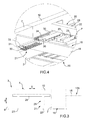
- unit 21 comprises a gantry frame 26, which is mounted substantially within one of the frames 4, is arranged outside the space with width L and in contact with the ground, and has two vertical uprights 27 parallel to direction 8 connected to one another, at the upper ends thereof, by a horizontal longitudinal member 28, which extends in direction 5, is arranged at a given distance from the corresponding longitudinal member 10 in direction 8, and has a guide 29 ( figure 5 ) obtained on a side face of the longitudinal member 10 parallel to direction 5 itself.
- guide 29 is slidingly engaged by a supporting bar 30, which protrudes from the longitudinal member 10 in direction 9, extends within the space with width L, and supports, in the case in hand, two gripping members 31, which protrude from the bar 30 towards the station 16 in direction 5, are arranged within the space with width L, and are fixed to the bar 30 in a lowered operating position.
- the members 31 are movable in direction 5 within a space having width L2 smaller than width L, measured parallel to direction 9, and each comprise a respective lower jaw 32 and a respective upper jaw 33 movable with respect to one another between a clamping position and a releasing position of at least one panel 2.
- the bar 30 further has a guide 34 which extends in direction 5, protrudes from the bar 30 from side opposite to the members 31 in direction 5, and is slidingly engaged by a shoe 35 fixed to a lower face of the bar 22 parallel to direction 5 itself.
- the machine 1 further comprises a stop device (not shown) interposed between the guide 34 and the shoe 35 and shaped so as to prevent the decoupling of the shoe 35 from the guide 34 in one sense or in both senses of direction 5.
- a stop device (not shown) interposed between the guide 34 and the shoe 35 and shaped so as to prevent the decoupling of the shoe 35 from the guide 34 in one sense or in both senses of direction 5.
- the bar 30, and thus the unit 22, are selectively locked onto the frame 26 and onto the bar 22 by means of respective locking devices 36, 37.
- the device 36 comprises two actuator cylinders (not shown), which are accommodated within the bar 30 on opposite sides of the guide 29 in direction 8, and have respective outlet rods 38 movable in direction 8 between an extracted locking position of the bar 30 on the guide 29 and a retracted releasing position.
- the device 37 comprises two actuator cylinders (not shown), which are accommodated within the shoe 35 on opposite sides of the guide 34 in direction 8, and have respective outlet rods 39 movable in direction 8 between an extracted locking position of the bar 30 on the bar 22 and a retracted releasing position.
- the displacement of the device 36 in its locking position and of the device 37 in its releasing position causes the locking of the unit 21 onto the frame 26 and the feeding through the cutting station 16 of the panels 2 carried by unit 20 only, while the displacement of the device 36 in its releasing position and of the device 37 in its locking position causes the locking of unit 21 onto unit 20 and the feeding through the station 16 of panels 2 carried by unit 20 and of panels 2 carried by unit 21.
- the displacement of unit 20 with respect to unit 21 is controlled by means of a measuring device (not shown) comprising, for instance, a magnetic band fixed to the guide 34 parallel to direction 5 and a sensor mounted on the shoe 35.
- a measuring device comprising, for instance, a magnetic band fixed to the guide 34 parallel to direction 5 and a sensor mounted on the shoe 35.
- the variant shown in figure 6 differs from that shown in the preceding figures only in that the gantry frame 26 is not present and the bar 30 is slidingly coupled to a guide 40 obtained on a lower face of one of the longitudinal members 10 parallel to direction 5.
- the bar 30 protrudes between the longitudinal members 10, and the members 31 are arranged within the space with width L.
- the variant shown in figure 7 differs from that shown in figure 6 only in that the bar 30 and the members 31 extend under the respective longitudinal member 10 and are thus arranged outside the space with width L.
- the bar 30 is thus arranged underneath the bar 22, and the members 31 are arranged within the space with width L.
- Bar 30 is thus arranged underneath bar 22, and members 31 are arranged within the space with width L.
- the machine 1 is relatively simple and cost-effective and allows to implement the unit 21 in machines designed and marketed only with unit 20 without requiring any changes to the electric cabinet or causing any operating assembly difficulties of unit 21.
Landscapes
- Life Sciences & Earth Sciences (AREA)
- Engineering & Computer Science (AREA)
- Mechanical Engineering (AREA)
- Wood Science & Technology (AREA)
- Forests & Forestry (AREA)
- Milling, Drilling, And Turning Of Wood (AREA)
Applications Claiming Priority (1)
| Application Number | Priority Date | Filing Date | Title |
|---|---|---|---|
| IT000398A ITBO20110398A1 (it) | 2011-07-01 | 2011-07-01 | Macchina sezionatrice per il taglio di pannelli di legno o simili |
Publications (2)
| Publication Number | Publication Date |
|---|---|
| EP2540429A1 true EP2540429A1 (fr) | 2013-01-02 |
| EP2540429B1 EP2540429B1 (fr) | 2018-09-05 |
Family
ID=44653396
Family Applications (1)
| Application Number | Title | Priority Date | Filing Date |
|---|---|---|---|
| EP12174674.7A Active EP2540429B1 (fr) | 2011-07-01 | 2012-07-02 | Machine de coupe pour panneaux de bois ou similaires |
Country Status (3)
| Country | Link |
|---|---|
| EP (1) | EP2540429B1 (fr) |
| ES (1) | ES2691214T3 (fr) |
| IT (1) | ITBO20110398A1 (fr) |
Cited By (10)
| Publication number | Priority date | Publication date | Assignee | Title |
|---|---|---|---|---|
| EP2941335A1 (fr) * | 2013-01-02 | 2015-11-11 | Valter Naldi | Machine de découpe de panneaux |
| CN105058505A (zh) * | 2015-08-24 | 2015-11-18 | 范县邢氏诚信木业有限公司 | 一种模板切割机 |
| ITUA20164117A1 (it) * | 2016-06-06 | 2017-12-06 | F O M Ind S R L | Macchina per la lavorazione di profilati |
| DE102017121958A1 (de) * | 2017-09-21 | 2019-03-21 | Homag Plattenaufteiltechnik Gmbh | Verfahren zum Aufteilen eines vorzugsweise plattenförmigen Werkstücks |
| DE102018110513A1 (de) * | 2018-05-02 | 2019-11-07 | Holz-Her Gmbh | Sägevorrichtung |
| IT201800009460A1 (it) | 2018-10-15 | 2020-04-15 | Biesse Spa | Macchina sezionatrice |
| CN112649221A (zh) * | 2021-01-06 | 2021-04-13 | 哈尔滨工程大学 | 一种木材原料含水率检测设备 |
| WO2022214472A1 (fr) * | 2021-04-07 | 2022-10-13 | Homag Plattenaufteiltechnik Gmbh | Dispositif de transport de pièces, installation d'usinage de plaques et procédé de fonctionnement d'un dispositif de transport de pièces |
| DE102021110333A1 (de) | 2021-04-22 | 2022-10-27 | Homag Plattenaufteiltechnik Gmbh | Vorbereitungsverfahren zum Vorbereiten der Aufteilung von mindestens zwei Werkstücken, Computerprogrammprodukt, computerlesbares Speichermedium, sowie Plattenaufteilanlage |
| DE102023112494A1 (de) | 2023-05-11 | 2024-11-14 | Homag Plattenaufteiltechnik Gmbh | Verfahren zum Betreiben einer Plattenbearbeitungsanlage, Plattenbearbeitungsanlage, sowie Steuereinrichtung für eine Plattenbearbeitungsanlage |
Citations (4)
| Publication number | Priority date | Publication date | Assignee | Title |
|---|---|---|---|---|
| US2657680A (en) * | 1950-08-29 | 1953-11-03 | Evans Harold | Sawing machine for stone and hard plastic material |
| US2945517A (en) * | 1956-12-06 | 1960-07-19 | Albert J Sower | Plural panel strip-cutting machine with traveling saw |
| US3946631A (en) * | 1974-03-04 | 1976-03-30 | Malm John A | Undercut saw |
| EP0911105A1 (fr) * | 1997-10-22 | 1999-04-28 | Selco Spa | Machine pour couper des corps plats à table rotative secondaire |
-
2011
- 2011-07-01 IT IT000398A patent/ITBO20110398A1/it unknown
-
2012
- 2012-07-02 EP EP12174674.7A patent/EP2540429B1/fr active Active
- 2012-07-02 ES ES12174674.7T patent/ES2691214T3/es active Active
Patent Citations (4)
| Publication number | Priority date | Publication date | Assignee | Title |
|---|---|---|---|---|
| US2657680A (en) * | 1950-08-29 | 1953-11-03 | Evans Harold | Sawing machine for stone and hard plastic material |
| US2945517A (en) * | 1956-12-06 | 1960-07-19 | Albert J Sower | Plural panel strip-cutting machine with traveling saw |
| US3946631A (en) * | 1974-03-04 | 1976-03-30 | Malm John A | Undercut saw |
| EP0911105A1 (fr) * | 1997-10-22 | 1999-04-28 | Selco Spa | Machine pour couper des corps plats à table rotative secondaire |
Cited By (14)
| Publication number | Priority date | Publication date | Assignee | Title |
|---|---|---|---|---|
| EP2941335A1 (fr) * | 2013-01-02 | 2015-11-11 | Valter Naldi | Machine de découpe de panneaux |
| CN105058505A (zh) * | 2015-08-24 | 2015-11-18 | 范县邢氏诚信木业有限公司 | 一种模板切割机 |
| ITUA20164117A1 (it) * | 2016-06-06 | 2017-12-06 | F O M Ind S R L | Macchina per la lavorazione di profilati |
| EP3254803A1 (fr) * | 2016-06-06 | 2017-12-13 | F.O.M. Industrie S.r.l. | Machine de traitement de barres de section |
| DE102017121958A1 (de) * | 2017-09-21 | 2019-03-21 | Homag Plattenaufteiltechnik Gmbh | Verfahren zum Aufteilen eines vorzugsweise plattenförmigen Werkstücks |
| DE102018110513A1 (de) * | 2018-05-02 | 2019-11-07 | Holz-Her Gmbh | Sägevorrichtung |
| IT201800009460A1 (it) | 2018-10-15 | 2020-04-15 | Biesse Spa | Macchina sezionatrice |
| EP3639993A1 (fr) | 2018-10-15 | 2020-04-22 | BIESSE S.p.A. | Machine à découper |
| CN112649221A (zh) * | 2021-01-06 | 2021-04-13 | 哈尔滨工程大学 | 一种木材原料含水率检测设备 |
| CN112649221B (zh) * | 2021-01-06 | 2022-09-27 | 舒城吉特育乐用品有限公司 | 一种木材原料含水率检测设备 |
| WO2022214472A1 (fr) * | 2021-04-07 | 2022-10-13 | Homag Plattenaufteiltechnik Gmbh | Dispositif de transport de pièces, installation d'usinage de plaques et procédé de fonctionnement d'un dispositif de transport de pièces |
| CN117157163A (zh) * | 2021-04-07 | 2023-12-01 | 豪迈面板分割科技有限公司 | 工件输送装置、板材加工设备和用于运行工件输送装置的方法 |
| DE102021110333A1 (de) | 2021-04-22 | 2022-10-27 | Homag Plattenaufteiltechnik Gmbh | Vorbereitungsverfahren zum Vorbereiten der Aufteilung von mindestens zwei Werkstücken, Computerprogrammprodukt, computerlesbares Speichermedium, sowie Plattenaufteilanlage |
| DE102023112494A1 (de) | 2023-05-11 | 2024-11-14 | Homag Plattenaufteiltechnik Gmbh | Verfahren zum Betreiben einer Plattenbearbeitungsanlage, Plattenbearbeitungsanlage, sowie Steuereinrichtung für eine Plattenbearbeitungsanlage |
Also Published As
| Publication number | Publication date |
|---|---|
| ITBO20110398A1 (it) | 2013-01-02 |
| ES2691214T3 (es) | 2018-11-26 |
| EP2540429B1 (fr) | 2018-09-05 |
Similar Documents
| Publication | Publication Date | Title |
|---|---|---|
| EP2540429B1 (fr) | Machine de coupe pour panneaux de bois ou similaires | |
| EP2251128B1 (fr) | Machine pour couper des plaques en bois ou similaires | |
| EP3647004B1 (fr) | Machine de découpage pour découper des panneaux en bois ou analogue | |
| EP3061582B1 (fr) | Machine pour découper des panneaux en bois ou similaire | |
| EP2574433B1 (fr) | Machine de coupe pour la coupe de panneaux en bois ou similaire | |
| KR101288254B1 (ko) | 절곡기용 판재 이송장치 | |
| EP2275388A1 (fr) | Procédé de manipulation et de découpe de plusieurs plaques et machine utilisée correspondante | |
| EP1815954A1 (fr) | Appareil pour traiter les composés en bois ou similaires | |
| EP3012053B1 (fr) | Machine pour découper des panneaux en bois, en plastique ou similaire | |
| EP2801430B1 (fr) | Machine à découper des panneaux de bois ou analogue | |
| EP0425700B1 (fr) | Dispositif transporteur de parties coupees pour machine a couper | |
| EP2210719A1 (fr) | Procédé de production de composants fabriqués en bois ou plastique | |
| EP2944409B1 (fr) | Machine pour la coupe de panneaux en bois ou en plastique | |
| EP3639957B1 (fr) | Machine pour découper des panneaux en bois ou analogue | |
| EP3639994B1 (fr) | Machine pour découper des panneaux en bois ou analogue | |
| EP3012052A1 (fr) | Machine pour découper des panneaux de bois ou analogue | |
| EP2275238B1 (fr) | Machine pour la découpe de panneaux de bois ou de matériaux similaires | |
| WO2010066519A1 (fr) | Machine permettant de couper des articles sensiblement en forme de blocs, composés en particulier de céramique, de matériaux semblables à de la pierre et similaires | |
| EP2868450B1 (fr) | Système de coupe pour couper des panneaux de bois ou similaire | |
| US20120213624A1 (en) | Tilting device for cropping a sheet of laminated glass | |
| EP2944408B1 (fr) | Machine pour la coupe des panneaux en bois ou en plastique | |
| CN205415896U (zh) | 实木零件全自动连续加工装置 | |
| ITTO20110759A1 (it) | Macchina sezionatrice per il taglio di pannelli di legno o simili | |
| CN210650805U (zh) | 一种新型的多功能标签切割机 | |
| EP3025835A1 (fr) | Machine pour traiter des panneaux de bois ou analogue |
Legal Events
| Date | Code | Title | Description |
|---|---|---|---|
| PUAI | Public reference made under article 153(3) epc to a published international application that has entered the european phase |
Free format text: ORIGINAL CODE: 0009012 |
|
| AK | Designated contracting states |
Kind code of ref document: A1 Designated state(s): AL AT BE BG CH CY CZ DE DK EE ES FI FR GB GR HR HU IE IS IT LI LT LU LV MC MK MT NL NO PL PT RO RS SE SI SK SM TR |
|
| AX | Request for extension of the european patent |
Extension state: BA ME |
|
| 17P | Request for examination filed |
Effective date: 20130701 |
|
| RBV | Designated contracting states (corrected) |
Designated state(s): AL AT BE BG CH CY CZ DE DK EE ES FI FR GB GR HR HU IE IS IT LI LT LU LV MC MK MT NL NO PL PT RO RS SE SI SK SM TR |
|
| 17Q | First examination report despatched |
Effective date: 20150924 |
|
| STAA | Information on the status of an ep patent application or granted ep patent |
Free format text: STATUS: EXAMINATION IS IN PROGRESS |
|
| GRAP | Despatch of communication of intention to grant a patent |
Free format text: ORIGINAL CODE: EPIDOSNIGR1 |
|
| STAA | Information on the status of an ep patent application or granted ep patent |
Free format text: STATUS: GRANT OF PATENT IS INTENDED |
|
| INTG | Intention to grant announced |
Effective date: 20180207 |
|
| GRAS | Grant fee paid |
Free format text: ORIGINAL CODE: EPIDOSNIGR3 |
|
| GRAA | (expected) grant |
Free format text: ORIGINAL CODE: 0009210 |
|
| STAA | Information on the status of an ep patent application or granted ep patent |
Free format text: STATUS: THE PATENT HAS BEEN GRANTED |
|
| AK | Designated contracting states |
Kind code of ref document: B1 Designated state(s): AL AT BE BG CH CY CZ DE DK EE ES FI FR GB GR HR HU IE IS IT LI LT LU LV MC MK MT NL NO PL PT RO RS SE SI SK SM TR |
|
| REG | Reference to a national code |
Ref country code: GB Ref legal event code: FG4D |
|
| REG | Reference to a national code |
Ref country code: CH Ref legal event code: EP |
|
| REG | Reference to a national code |
Ref country code: AT Ref legal event code: REF Ref document number: 1037249 Country of ref document: AT Kind code of ref document: T Effective date: 20180915 |
|
| REG | Reference to a national code |
Ref country code: IE Ref legal event code: FG4D |
|
| REG | Reference to a national code |
Ref country code: DE Ref legal event code: R096 Ref document number: 602012050571 Country of ref document: DE |
|
| REG | Reference to a national code |
Ref country code: ES Ref legal event code: FG2A Ref document number: 2691214 Country of ref document: ES Kind code of ref document: T3 Effective date: 20181126 |
|
| REG | Reference to a national code |
Ref country code: NL Ref legal event code: MP Effective date: 20180905 |
|
| REG | Reference to a national code |
Ref country code: LT Ref legal event code: MG4D |
|
| PG25 | Lapsed in a contracting state [announced via postgrant information from national office to epo] |
Ref country code: NO Free format text: LAPSE BECAUSE OF FAILURE TO SUBMIT A TRANSLATION OF THE DESCRIPTION OR TO PAY THE FEE WITHIN THE PRESCRIBED TIME-LIMIT Effective date: 20181205 Ref country code: GR Free format text: LAPSE BECAUSE OF FAILURE TO SUBMIT A TRANSLATION OF THE DESCRIPTION OR TO PAY THE FEE WITHIN THE PRESCRIBED TIME-LIMIT Effective date: 20181206 Ref country code: BG Free format text: LAPSE BECAUSE OF FAILURE TO SUBMIT A TRANSLATION OF THE DESCRIPTION OR TO PAY THE FEE WITHIN THE PRESCRIBED TIME-LIMIT Effective date: 20181205 Ref country code: FI Free format text: LAPSE BECAUSE OF FAILURE TO SUBMIT A TRANSLATION OF THE DESCRIPTION OR TO PAY THE FEE WITHIN THE PRESCRIBED TIME-LIMIT Effective date: 20180905 Ref country code: LT Free format text: LAPSE BECAUSE OF FAILURE TO SUBMIT A TRANSLATION OF THE DESCRIPTION OR TO PAY THE FEE WITHIN THE PRESCRIBED TIME-LIMIT Effective date: 20180905 Ref country code: RS Free format text: LAPSE BECAUSE OF FAILURE TO SUBMIT A TRANSLATION OF THE DESCRIPTION OR TO PAY THE FEE WITHIN THE PRESCRIBED TIME-LIMIT Effective date: 20180905 Ref country code: SE Free format text: LAPSE BECAUSE OF FAILURE TO SUBMIT A TRANSLATION OF THE DESCRIPTION OR TO PAY THE FEE WITHIN THE PRESCRIBED TIME-LIMIT Effective date: 20180905 |
|
| PG25 | Lapsed in a contracting state [announced via postgrant information from national office to epo] |
Ref country code: AL Free format text: LAPSE BECAUSE OF FAILURE TO SUBMIT A TRANSLATION OF THE DESCRIPTION OR TO PAY THE FEE WITHIN THE PRESCRIBED TIME-LIMIT Effective date: 20180905 Ref country code: LV Free format text: LAPSE BECAUSE OF FAILURE TO SUBMIT A TRANSLATION OF THE DESCRIPTION OR TO PAY THE FEE WITHIN THE PRESCRIBED TIME-LIMIT Effective date: 20180905 Ref country code: HR Free format text: LAPSE BECAUSE OF FAILURE TO SUBMIT A TRANSLATION OF THE DESCRIPTION OR TO PAY THE FEE WITHIN THE PRESCRIBED TIME-LIMIT Effective date: 20180905 |
|
| PG25 | Lapsed in a contracting state [announced via postgrant information from national office to epo] |
Ref country code: PL Free format text: LAPSE BECAUSE OF FAILURE TO SUBMIT A TRANSLATION OF THE DESCRIPTION OR TO PAY THE FEE WITHIN THE PRESCRIBED TIME-LIMIT Effective date: 20180905 Ref country code: EE Free format text: LAPSE BECAUSE OF FAILURE TO SUBMIT A TRANSLATION OF THE DESCRIPTION OR TO PAY THE FEE WITHIN THE PRESCRIBED TIME-LIMIT Effective date: 20180905 Ref country code: IS Free format text: LAPSE BECAUSE OF FAILURE TO SUBMIT A TRANSLATION OF THE DESCRIPTION OR TO PAY THE FEE WITHIN THE PRESCRIBED TIME-LIMIT Effective date: 20190105 Ref country code: CZ Free format text: LAPSE BECAUSE OF FAILURE TO SUBMIT A TRANSLATION OF THE DESCRIPTION OR TO PAY THE FEE WITHIN THE PRESCRIBED TIME-LIMIT Effective date: 20180905 Ref country code: NL Free format text: LAPSE BECAUSE OF FAILURE TO SUBMIT A TRANSLATION OF THE DESCRIPTION OR TO PAY THE FEE WITHIN THE PRESCRIBED TIME-LIMIT Effective date: 20180905 Ref country code: RO Free format text: LAPSE BECAUSE OF FAILURE TO SUBMIT A TRANSLATION OF THE DESCRIPTION OR TO PAY THE FEE WITHIN THE PRESCRIBED TIME-LIMIT Effective date: 20180905 |
|
| PG25 | Lapsed in a contracting state [announced via postgrant information from national office to epo] |
Ref country code: SM Free format text: LAPSE BECAUSE OF FAILURE TO SUBMIT A TRANSLATION OF THE DESCRIPTION OR TO PAY THE FEE WITHIN THE PRESCRIBED TIME-LIMIT Effective date: 20180905 Ref country code: PT Free format text: LAPSE BECAUSE OF FAILURE TO SUBMIT A TRANSLATION OF THE DESCRIPTION OR TO PAY THE FEE WITHIN THE PRESCRIBED TIME-LIMIT Effective date: 20190105 Ref country code: SK Free format text: LAPSE BECAUSE OF FAILURE TO SUBMIT A TRANSLATION OF THE DESCRIPTION OR TO PAY THE FEE WITHIN THE PRESCRIBED TIME-LIMIT Effective date: 20180905 |
|
| REG | Reference to a national code |
Ref country code: DE Ref legal event code: R097 Ref document number: 602012050571 Country of ref document: DE |
|
| PLBE | No opposition filed within time limit |
Free format text: ORIGINAL CODE: 0009261 |
|
| STAA | Information on the status of an ep patent application or granted ep patent |
Free format text: STATUS: NO OPPOSITION FILED WITHIN TIME LIMIT |
|
| PG25 | Lapsed in a contracting state [announced via postgrant information from national office to epo] |
Ref country code: DK Free format text: LAPSE BECAUSE OF FAILURE TO SUBMIT A TRANSLATION OF THE DESCRIPTION OR TO PAY THE FEE WITHIN THE PRESCRIBED TIME-LIMIT Effective date: 20180905 |
|
| 26N | No opposition filed |
Effective date: 20190606 |
|
| PG25 | Lapsed in a contracting state [announced via postgrant information from national office to epo] |
Ref country code: SI Free format text: LAPSE BECAUSE OF FAILURE TO SUBMIT A TRANSLATION OF THE DESCRIPTION OR TO PAY THE FEE WITHIN THE PRESCRIBED TIME-LIMIT Effective date: 20180905 |
|
| PG25 | Lapsed in a contracting state [announced via postgrant information from national office to epo] |
Ref country code: MC Free format text: LAPSE BECAUSE OF FAILURE TO SUBMIT A TRANSLATION OF THE DESCRIPTION OR TO PAY THE FEE WITHIN THE PRESCRIBED TIME-LIMIT Effective date: 20180905 |
|
| REG | Reference to a national code |
Ref country code: CH Ref legal event code: PL |
|
| GBPC | Gb: european patent ceased through non-payment of renewal fee |
Effective date: 20190702 |
|
| PG25 | Lapsed in a contracting state [announced via postgrant information from national office to epo] |
Ref country code: TR Free format text: LAPSE BECAUSE OF FAILURE TO SUBMIT A TRANSLATION OF THE DESCRIPTION OR TO PAY THE FEE WITHIN THE PRESCRIBED TIME-LIMIT Effective date: 20180905 |
|
| REG | Reference to a national code |
Ref country code: BE Ref legal event code: MM Effective date: 20190731 |
|
| PG25 | Lapsed in a contracting state [announced via postgrant information from national office to epo] |
Ref country code: GB Free format text: LAPSE BECAUSE OF NON-PAYMENT OF DUE FEES Effective date: 20190702 |
|
| PG25 | Lapsed in a contracting state [announced via postgrant information from national office to epo] |
Ref country code: BE Free format text: LAPSE BECAUSE OF NON-PAYMENT OF DUE FEES Effective date: 20190731 Ref country code: LU Free format text: LAPSE BECAUSE OF NON-PAYMENT OF DUE FEES Effective date: 20190702 Ref country code: CH Free format text: LAPSE BECAUSE OF NON-PAYMENT OF DUE FEES Effective date: 20190731 Ref country code: LI Free format text: LAPSE BECAUSE OF NON-PAYMENT OF DUE FEES Effective date: 20190731 |
|
| PG25 | Lapsed in a contracting state [announced via postgrant information from national office to epo] |
Ref country code: FR Free format text: LAPSE BECAUSE OF NON-PAYMENT OF DUE FEES Effective date: 20190731 |
|
| PG25 | Lapsed in a contracting state [announced via postgrant information from national office to epo] |
Ref country code: IE Free format text: LAPSE BECAUSE OF NON-PAYMENT OF DUE FEES Effective date: 20190702 |
|
| PG25 | Lapsed in a contracting state [announced via postgrant information from national office to epo] |
Ref country code: CY Free format text: LAPSE BECAUSE OF FAILURE TO SUBMIT A TRANSLATION OF THE DESCRIPTION OR TO PAY THE FEE WITHIN THE PRESCRIBED TIME-LIMIT Effective date: 20180905 |
|
| PG25 | Lapsed in a contracting state [announced via postgrant information from national office to epo] |
Ref country code: HU Free format text: LAPSE BECAUSE OF FAILURE TO SUBMIT A TRANSLATION OF THE DESCRIPTION OR TO PAY THE FEE WITHIN THE PRESCRIBED TIME-LIMIT; INVALID AB INITIO Effective date: 20120702 Ref country code: MT Free format text: LAPSE BECAUSE OF FAILURE TO SUBMIT A TRANSLATION OF THE DESCRIPTION OR TO PAY THE FEE WITHIN THE PRESCRIBED TIME-LIMIT Effective date: 20180905 |
|
| REG | Reference to a national code |
Ref country code: AT Ref legal event code: UEP Ref document number: 1037249 Country of ref document: AT Kind code of ref document: T Effective date: 20180905 |
|
| PG25 | Lapsed in a contracting state [announced via postgrant information from national office to epo] |
Ref country code: MK Free format text: LAPSE BECAUSE OF FAILURE TO SUBMIT A TRANSLATION OF THE DESCRIPTION OR TO PAY THE FEE WITHIN THE PRESCRIBED TIME-LIMIT Effective date: 20180905 |
|
| PGFP | Annual fee paid to national office [announced via postgrant information from national office to epo] |
Ref country code: ES Payment date: 20250812 Year of fee payment: 14 |
|
| PGFP | Annual fee paid to national office [announced via postgrant information from national office to epo] |
Ref country code: DE Payment date: 20250728 Year of fee payment: 14 |
|
| PGFP | Annual fee paid to national office [announced via postgrant information from national office to epo] |
Ref country code: IT Payment date: 20250623 Year of fee payment: 14 |
|
| PGFP | Annual fee paid to national office [announced via postgrant information from national office to epo] |
Ref country code: AT Payment date: 20250718 Year of fee payment: 14 |