EP2540603A2 - Véhicule de type à enfourcher - Google Patents
Véhicule de type à enfourcher Download PDFInfo
- Publication number
- EP2540603A2 EP2540603A2 EP20120173820 EP12173820A EP2540603A2 EP 2540603 A2 EP2540603 A2 EP 2540603A2 EP 20120173820 EP20120173820 EP 20120173820 EP 12173820 A EP12173820 A EP 12173820A EP 2540603 A2 EP2540603 A2 EP 2540603A2
- Authority
- EP
- European Patent Office
- Prior art keywords
- vehicle
- swing
- supporting portion
- swing member
- swing arm
- Prior art date
- Legal status (The legal status is an assumption and is not a legal conclusion. Google has not performed a legal analysis and makes no representation as to the accuracy of the status listed.)
- Granted
Links
Images



Classifications
-
- B—PERFORMING OPERATIONS; TRANSPORTING
- B62—LAND VEHICLES FOR TRAVELLING OTHERWISE THAN ON RAILS
- B62J—CYCLE SADDLES OR SEATS; AUXILIARY DEVICES OR ACCESSORIES SPECIALLY ADAPTED TO CYCLES AND NOT OTHERWISE PROVIDED FOR, e.g. ARTICLE CARRIERS OR CYCLE PROTECTORS
- B62J15/00—Mud-guards for wheels
-
- B—PERFORMING OPERATIONS; TRANSPORTING
- B62—LAND VEHICLES FOR TRAVELLING OTHERWISE THAN ON RAILS
- B62K—CYCLES; CYCLE FRAMES; CYCLE STEERING DEVICES; RIDER-OPERATED TERMINAL CONTROLS SPECIALLY ADAPTED FOR CYCLES; CYCLE AXLE SUSPENSIONS; CYCLE SIDECARS, FORECARS, OR THE LIKE
- B62K2202/00—Motorised scooters
Definitions
- This invention relates to a saddle type vehicle, and particularly to improvements in a structure of a rear portion of a saddle type vehicle.
- a saddle type vehicle wherein a hydraulic rear wheel brake is provided for a rear wheel is known (refer to, for example, Japanese Patent Laid-Open No. Hei 3-253485 , figure 1 and figure 2 ).
- a support shaft (21) is provided through a bracket (19), and a unit swing engine (20) is supported for upward and downward rocking motion on the support shaft 21.
- a rear wheel brake system is provided in such a saddle type vehicle as described above.
- the rear wheel brake system includes a master cylinder (51) provided at a front portion of the vehicle and serving as a pressure generating source, a brake hose (72) extending rearwardly of the vehicle from the master cylinder (51), and a disk brake (73) to which an end of the brake hose (72) is connected.
- the brake hose (72) is covered with a front cover (11) and a rear cover (16) indicated by imaginary lines.
- the brake hose (72) is attached to the rear frame (15) by a band (75) and supported on a support bracket (26) of the unit swing engine (20) by a holder (76).
- the brake hose (72) extends generally in a forward and backward direction of the vehicle between the band (75) and the support bracket (26).
- the brake hose (72) may be deflected in all of the vehicle longitudinal direction and the leftward and rightward vehicle widthwise direction.
- the brake hose (72) has a deflection margin in order to cope with the rocking motion.
- the rear cover (16) is designed taking the deflection margin into consideration.
- the rear cover (16) Since the brake hose (72) is deflected leftwardly and rightwardly in the vehicle widthwise direction, the rear cover (16) is provided in a swollen state in the vehicle widthwise direction, resulting in increase in size. If the rear cover (16) becomes larger in this manner, the vehicle body becomes great.
- a technique for decreasing the size of the vehicle body in a saddle type vehicle which includes a hydraulic brake for braking a rear wheel is demanded.
- a saddle type vehicle including a vehicle body frame including a pair of left and right rear frames and covered with a vehicle body cover, a swing member supported for upward and downward rocking motion on the vehicle body frame at a position below the paired left and right rear frames and extending in a vehicle rearward direction, a rear wheel supported at a rear portion of the swing member, a hydraulic brake supported on the swing member and configured to brake the rear wheel, and a hydraulic pipe connected to the hydraulic brake and disposed along one side of the paired left and right rear frames and further along the swing member for transmitting a hydraulic pressure for operating the hydraulic brake, wherein a frame side supporting portion disposed at an upper portion of the swing member as viewed in a vehicle side view and supporting the hydraulic pipe thereon is provided on the rear frames while a swing arm side supporting portion for supporting the hydraulic pipe thereon is provided on the swing member; the hydraulic pipe includes a first hydraulic pipe extending from a hydraulic pressure generation section to the frame side supporting portion, a flexible tube extending from the
- a rear fender integrally rockable with the swing member to avoid mud splashed by the rear wheel is provided for the rear wheel and is fastened to the swing member together with the swing arm side supporting portion.
- the swing member includes a power unit for generating power and a swing arm extending in the vehicle rearward direction from the opposite side of the power unit in the left and right vehicle widthwise direction; the swing arm side supporting portion is provided on the swing arm; and the flexible tube is disposed in the curved state to the other side in the left and right vehicle widthwise direction at the position above the power unit and is deflected when the swing member rocks upwardly and downwardly to absorb the rocking motion of the swing member.
- a rear fender integrally rockable with a unit swing to avoid mud splashed by the rear wheel is provided for the rear wheel, and a forward extension which covers a crankcase upper face of the power unit is provided on the rear fender.
- the power unit is an engine which includes a crankcase and a cylinder projecting a vehicle forward direction from the crankcase, and a radiator is provided on one side of the crankcase in the vehicle widthwise direction.
- the radiator includes a feed-water cap provided at an upper portion thereof.
- the flexible tube piped between the swing arm side supporting portion and the frame side supporting portion is disposed in a curved state from one side to the other side in the left and right vehicle widthwise direction in front of the rear wheel.
- the flexible tube is disposed in a curved state such that it is swollen to the vehicle body center.
- the flexible tube When the swing member is rocked, the flexible tube is deflected so as to move toward and away from the center in the vehicle widthwise direction. Since the flexible tube which is likely to be deflected to the center in the vehicle widthwise direction is used, the vehicle body cover can be reduced in size in comparison with a flexible tube which is likely to be deflected in any of the vehicle longitudinal direction and the vehicle widthwise direction. If the vehicle body cover can be reduced in size, then the vehicle body can be reduced in size.
- the flexible tube is disposed such that it is deflected in front of the rear wheel.
- the flexible tube is disposed otherwise such that it is deflected upwardly or sidewardly with respect to the rear frame, then in order to assure a deflection margin, the vehicle height is increased or the vehicle width is increased.
- the flexible tube is disposed in front of the rear wheel, a sufficient deflection margin can be assured without increasing the height of the vehicle.
- the flexible tube is disposed at the position above the swing member. Since the flexible tube of the hydraulic pipe is disposed utilizing a place above the swing member which is liable to become a dead space, the vehicle body can be made more compact.
- the rear fender integrally rockable with the swing member to avoid mud is fastened together with the swing arm side supporting portion. Since the rear fender is fastened together with the hydraulic pipe, the number of parts can be reduced in comparison with an alternative case in which the rear fender is fastened to the swing member and the swing arm side supporting portion is fastened to the swing member.
- the swing member includes the power unit for generating power and the swing arm extending in the vehicle rearward direction from the one side of the power unit in the left and right vehicle widthwise direction, and the swing arm side supporting portion is provided on the swing arm.
- the flexible tube is provided in a curved state from the swing arm provided on the one side in the leftward and rightward vehicle widthwise direction to the other side in front of the rear wheel.
- the flexible tube is disposed in a curved state so as to be swollen to the vehicle body center.
- the flexible tube When the swing member is rocked, the flexible tube is deflected so as to move toward and away from the vehicle widthwise center. Since the flexible tube which is likely to be deflected to the center in the vehicle widthwise direction, the vehicle body cover can be reduced in size. If the vehicle body cover is reduced in size, then the vehicle body can be reduced in size.
- the forward extension which covers the crankcase upper face is provided on the rear fender. Generated heat of the crankcase is shielded by the forward extension of the rear fender. Since the power unit and the hydraulic pipe are isolated from each other by the forward extension, it is possible to make it hard to transmit heat of the crankcase to the hydraulic pipe without additionally providing a separate shield member.
- the power unit is the engine, and the radiator is provided sidewardly of the crankcase of the engine.
- the hydraulic pipe is disposed above the crankcase which configures the power unit, and the radiator is disposed sidewardly of the crankcase.
- the radiator includes the feed-water cap provided at the upper portion thereof. Since the feed-water cap is disposed avoiding the hydraulic pipe, it can be caught readily by a hand and a water supplying operation is facilitated. In addition, since the hydraulic pipe is piped so as to avoid the radiator having the feed-water cap, the hydraulic pipe can be caught readily by a hand, and ease of the maintenance of the hydraulic pipe can be enhanced.
- a motorcycle 10 is a saddle type vehicle which has a front wheel 12 disposed at a vehicle front portion and provided for steering operation by a handle bar 11, an engine 14 disposed rearwardly of the vehicle with respect to the front wheel 12 and serving as a power unit 13, a rear wheel 16 disposed rearwardly with respect to the engine 14 and driven by the engine 14, and a seat 17 provided between the front wheel 12 and the rear wheel 16, and has a form in which an occupant is seated on and across the seat 17.
- the motorcycle 10 is a vehicle wherein it includes a vehicle body frame 20 and a unit swing 22 is supported for rocking motion on the vehicle body frame 20.
- a steering system 21 including the handle bar 11 is provided at a front portion of the vehicle body frame 20 and a link pivot 23 is attached to a lower portion of the vehicle body frame 20, and a link 28 is attached to the link pivot 23.
- a swing arm pivot 24 is provided at a rear portion of the link 28, and the unit swing 22 is attached to the swing arm pivot 24.
- the vehicle body frame 20 includes, as principal components thereof, a head pipe 31 having the steering system 21 supported at a front end portion thereof for steering pivotal motion, a down frame 32 extending rearwardly downwards of the vehicle from the head pipe 31, a pair of left and right lower frames 33L and 33R (only the reference character 33R on this side of the figure is shown) extending rearwardly of the vehicle from a lower portion of the down frame 32 and further extending obliquely rearwardly upwards of the vehicle, and rear frames 34L and 34R (only the reference character 34R on this side of the figure is shown) attached to rear end portions of the lower frames 33L and 33R and extending rearwardly upwards of the vehicle.
- a U-shaped member 37 which exhibits a substantially U shape as viewed in plan of the vehicle and supports an accommodation box 41 thereon extends between left and right inclined portions 36L and 36R (only the reference character 36R on this side of the figure is shown) which configure portions of the lower frames 33L and 33R which extend rearwardly upwards of the vehicle such that the closing side thereof is positioned forwardly.
- the left and right rear frames are secured at front ends 34La and 34Ra (only the reference character 34Ra on this side of the figure is shown) thereof to an intermediate portion of the U-shaped member 37.
- Left and right link brackets 43L and 43R each in the form of a plate are secured to the left and right lower frames 33L and 33R, respectively.
- the engine 14 as the power unit 13 which generates power is provided integrally.
- Left and right cushion units 45L and 45R are interposed between a rear portion of the unit swing 22 and the vehicle body frame 20. Further, an air cleaner 48 which configures an intake system 47 is provided on the unit swing 22.
- the steering system 21 of the motorcycle 10 is configured from a steering shaft 51 provided for rotation at a front end portion of the vehicle body frame 20, a front fork 52 connected to a lower end of the steering shaft 21 for supporting the front wheel 12, and the handle bar 11 attached to an upper end of the steering shaft 51.
- the vehicle body frame 20 of the motorcycle 10 is converted with a vehicle body cover 60.
- the vehicle body cover 60 has a front cover 61 which covers the vehicle body from forwardly, a center cowl 62 attached to the front cover 61 in such a manner as to cover an upper portion of the center cowl 62 from rearwardly of the vehicle, left and right under covers 64L and 64R (only the reference character 64R on this side of the figure is shown) extending rearwardly of the vehicle from a lower end of the center cowl 62 and having left and right steps 63L and 63R (only the reference character 63R on this side of the figure is shown) for receiving the feet of a rider placed thereon, respectively, and left and right rear side covers 65L and 65R (only the reference character 65R on this side of the figure is shown) extending rearwardly of the vehicle under the seat 17.
- the accommodation box 41 for receiving an article fitted therein is attached to the left and right rear frames 34L and 34R, and a fuel tank 67 is attached to the left and right rear frames 34L and 34R rearwardly of the vehicle with respect to the accommodation box 41.
- the seat 17 is placed on the accommodation box 41 and the fuel tank 67 in such a manner as to cover the accommodation box 41 and the fuel tank 67 from above.
- the power unit 13 for generating power is included in the unit swing 22 and is supported for upward and downward rocking motion on the vehicle body frame 20 at a position below the paired left and right rear frames 34L and 34R.
- the unit swing 22 supports the rear wheel 16 at the rear portion thereof.
- a front fender 53 for avoiding mud splashed by the front wheel 12 is attached to the front fork 52 above the front wheel 12, and a first rear fender 71 for avoiding mud splashed by the rear wheel 16 is attached to the rear frames 34L and 34R rearwardly upwardly with respect to the rear wheel 16. Meanwhile, a second rear fender 72 integrally rockable with the unit swing 22 for avoiding mud splashed by the rear wheel 16 is attached to the unit swing 22 forwardly upwardly with respect to the rear wheel 16.
- the power unit 13 has a crankcase 75, a cylinder 76 (cylinder block 76) projecting forwardly of the vehicle from the crankcase 75, a cylinder head 77 attached to a front end of the cylinder block 76, and a head cover 78 placed over a front end of the cylinder head 77.
- An engine block 79 which configures a main body of the engine 14 is configured from the crankcase 75, cylinder block 76, cylinder head 77 and head cover 78.
- the intake system 47 is connected to an upper face of the cylinder head 77
- an exhaust system 81 is connected to a lower face of the cylinder head 77.
- the intake system 47 includes, as principal components thereof, a throttle body 49 connected to the cylinder head 77 for adjusting the fuel supply amount, the air cleaner 48 connected to the intake system 47 for supplying clean air, and a connecting tube 50 for connecting the throttle body 49 and the air cleaner 48 to each other.
- the exhaust system 81 includes, as principal components thereof, an exhaust pipe 82 extending downwardly from the cylinder head 77 and further extending rearwardly of the vehicle, and a muffler 83 connected to a vehicle rear end of the exhaust pipe 82.
- the muffler 83 is covered with a muffler cover 84 from outwardly in the vehicle widthwise direction.
- a rear wheel brake 90 is a hydraulic disk brake and is configured from a brake master cylinder 92, a first hydraulic pipe 95, a frame side supporting portion 101, a flexible tube 97, a second hydraulic pipe 96, and a hydraulic brake 103.
- the brake master cylinder 92 serves as a hydraulic pressure generation section provided on the left side in the vehicle widthwise direction with respect to the handle bar 11 and driven by a left lever not shown.
- the first hydraulic pipe 95 is piped in order from the brake master cylinder 92 along the head pipe 31, down frame 32, lower frame 33R and rear frame 34R.
- the frame side supporting portion 101 is provided on the rear frame 34R at a rear end portion of the first hydraulic pipe 95 and disposed at an upper portion of the unit swing 22 as viewed in side elevation of the vehicle and supports a hydraulic pipe 94 thereon.
- the flexible tube 97 extends from the frame side supporting portion 101 to a swing arm side supporting portion 102 which is provided on a swing arm 26 and supports the hydraulic pipe 94 thereon.
- the second hydraulic pipe 96 is connected to the flexible tube 97 and extends from the swing arm side supporting portion 102.
- the hydraulic brake 103 is connected to an end of the second hydraulic pipe 96.
- the hydraulic pipe 94 is a pipe for transmitting a hydraulic pressure for operating the rear wheel brake 90 in the form of a hydraulic brake and is connected to the rear wheel brake 90 and piped along the right side rear frame 34R and then along the swing arm 26.
- the rear wheel brake 90 is a unit supported on the swing arm 26 for braking the rear wheel 16, and is configured from a brake disk 105 for integrally rotating with the rear wheel 16, and a brake caliper 106 provided at a position at which it can clamp the brake disk 105 and attached to the swing arm 26.
- an engine cooling section 110 provided for the engine 14 has a radiator unit 111 attached to the crankcase 75 rightwardly sidewardly in the vehicle widthwise direction, and a feed-water inlet 112 provided at an upper portion of the radiator unit 111 for supplementing cooling water therethrough and a feed-water cap 113 for covering the feed-water inlet 112 to open and close the same.
- the engine cooling section 110 further has a feed pipe 114 extending from a lower portion of the radiator unit 111 for feeding cooling water to the engine block 79, and a return pipe 115 for returning cooling water warmed by the engine 14 to the radiator unit 111.
- radiator unit may be attached leftwardly sidewardly of the crankcase in the vehicle widthwise direction.
- the link pivot 23 extending in the vehicle widthwise direction is supported on the left and right link brackets 43L and 43R, and the unit swing 22 extends rearwardly of the vehicle through a swing arm pivot ( Fig. 3 , reference numeral 24) extending in the vehicle widthwise direction at a rear portion of the vehicle with respect to the link pivot 23.
- the power unit 13 including a variable speed transmission 117 extends rearwardly of the vehicle on the left side in the vehicle widthwise direction, and the swing arm 26 extends rearwardly of the vehicle on the right side in the vehicle widthwise direction.
- the unit swing 22 is configured from the power unit 13 extending rearwardly of the vehicle from the left side in the vehicle widthwise direction, and the swing arm 26 extending rearwardly of the vehicle from the right side in the vehicle widthwise direction.
- the muffler 83 is attached to the swing arm 26, and the brake caliper 106 is attached.
- the second rear fender 72 provided in such a manner as to cover the rear wheel 16 is fastened to the swing arm 26 on the right side in the vehicle widthwise direction through fastening members 121 and 122 and is fastened to the air cleaner 48 on the left side in the vehicle widthwise direction through a fastening member 123.
- the second rear fender 72 has a forward extension 73 provided thereon for covering a crankcase upper face 75a of the power unit 13.
- the radiator unit 111 provided on the right side in the vehicle widthwise direction with respect to the engine 14 includes the feed-water cap 113 provided at an upper portion thereof such that it is opened and closed when cooling water is to be supplied.
- Reference character C in the figure denotes a center line of the feed-water cap 113 in the vehicle widthwise direction.
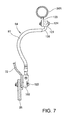
- the flexible tube 97 extending between the frame side supporting portion 101 and the swing arm side supporting portion 102 is disposed at a position above the power unit 13.
- an imaginary line I is a line of the flexible tube 97 where it extends linearly between the frame side supporting portion 101 and the swing arm side supporting portion 102. Where the flexible tube 97 extends linearly, it can be disposed in a spaced relationship from the feed-water cap 113, and consequently, it is easy to carry out a mounting or dismounting operation of the feed-water cap 113 or a water supplying operation.
- the swing arm side supporting portion 102 is disposed rearwardly downwards with respect to the frame side supporting portion 101 and besides the flexible tube 97 is curved to the left side in the vehicle widthwise direction which is the other side, when a water supplying operation is carried out, there is no possibility that the vehicle body cover or the like may make an obstacle, and supplying of water from rearwardly upwards can be carried out readily.
- the flexible tube 97 is disposed in a curved state to the left side in the vehicle widthwise direction in front of the rear wheel 16 and is deflected, when the unit swing 22 is rocked upwardly and downwardly, to absorb the rocking motion of the unit swing 22.
- a swing member 25 includes the power unit 13, and the swing arm 26 extending rearwardly of the vehicle from the right side in the vehicle widthwise direction which is the opposite side of the power unit 13 in the leftward and rightward direction.
- the unit swing 22 is configured from the power unit 13 including the variable speed transmission 117 disposed on the left side in the vehicle widthwise direction, and the swing arm 26 disposed on the right side in the vehicle widthwise direction.
- the variable speed transmission 117 transmits power from the engine 14 to the rear wheel 16 and changes the speed of rotation of the rear wheel 16 steplessly.
- An internal structure of the variable speed transmission 117 is omitted.
- the air cleaner 48 is attached to the top of the variable speed transmission 117, and the muffler 83 is attached to the swing arm 26 outwardly in the vehicle widthwise direction.
- the width W between the left and right rear frames 34L and 34R is made greater to assure the rigidity of the vehicle body frame 20 and the swing arm 26 is displaced to the inner side in the vehicle widthwise direction with respect to the width W between the rear frames 34L and 34R to assure a greater bank angle of the vehicle.
- the frame side supporting portion 101 is disposed on the outer side of the vehicle with respect to the center line C in the vehicle widthwise direction of the feed-water cap 113, and the swing arm side supporting portion 102 is disposed on the inner side of the vehicle with respect to the center line C in the vehicle widthwise direction of the feed-water cap 113. Therefore, although, if the flexible tube 97 is simply disposed linearly, then it becomes very hard to carry out a water supplying operation, in the embodiment, since the flexible tube 97 is spaced away from the feed-water cap 113, the flexible tube 97 is less likely to make an obstacle to a water supplying operation and also the water supplying operability becomes better.
- the imaginary line I is a line linearly interconnecting the flexible tube 97 between the frame side supporting portion 101 and the swing arm side supporting portion 102. Since the flexible tube 97 can be disposed in a spaced relationship from the feed-water cap 113 in comparison with an alternative case wherein the flexible tube 97 extends linearly, a mounting or dismounting operation of the feed-water cap 113 or a water supplying operation can be carried out readily.
- the connecting tube 50 extending from the throttle body 49 to the air cleaner 48 is piped such that it extends to the left side in the vehicle widthwise direction which is the other side, and consequently, the flexible tube 97 is piped in a dead space formed in this manner on the right side in the vehicle widthwise direction which is the one side.
- the second rear fender 72 is placed on the outer side of the swing arm 26 in the vehicle widthwise direction, and the swing arm side supporting portion 102 is disposed outwardly of the second rear fender 72. Then, the second rear fender 72 and the swing arm side supporting portion 102 are fastened together to the swing arm 26 by the fastening member 122 from outwardly in the vehicle widthwise direction.
- the second rear fender 72 which rocks integrally with the unit swing 22 to avoid mud is fastened together to the flexible tube 97 which configures the hydraulic pipe 94, the number of parts can be reduced in comparison with that in an alternative case in which the second rear fender 72 and the swing arm side supporting portion 102 are individually fastened to the swing arm 26.
- a stay 125 is extended downwardly from the rear frame 34R, and the frame side supporting portion 101 which supports the hydraulic pipe 94 is fastened to the stay 125 by a fastening member 124.
- the exit of the frame side supporting portion 101 is directed inwardly in the vehicle widthwise direction and has an inwardly directed portion 126 to which the flexible tube 97 is fastened, and this inwardly directed portion 126 makes it easy to direct the flexible tube 97 inwardly in the vehicle widthwise direction.
- Fig. 8(a) is a view illustrating deflection of the flexible tube 97 when the unit swing ( Fig. 5 , symbol 22) is rocked to a lower end position.
- Fig. 8(b) is a view illustrating deflection of the flexible tube 97 when the unit swing 22 is rocked to an upper end position.
- the swing arm 26 which configures the unit swing 22 moves upwardly by a length 8
- the flexible tube 97 connected to the inwardly directed portion 126 and piped between the swing arm side supporting portion 102 and the frame side supporting portion 101 is disposed in a curved state to the left side in the vehicle widthwise direction.
- the flexible tube 97 disposed in a curved state to the left side in the vehicle widthwise direction is deflected toward the center in the vehicle widthwise direction.
- the vehicle body can be reduced in size without making the vehicle body covers 65L and 65R greater outwardly in the vehicle longitudinal direction and/or the vehicle widthwise direction.
- the flexible tube 97 is disposed at a position above the power unit 13. Since the place above the power unit 13 which is likely to become a dead space is utilized to dispose the flexible tube 97 of the hydraulic pipe 94 therein, further compaction of the vehicle body can be anticipated.
- the flexible tube 97 is disposed in such a manner as to be deflected in the vehicle widthwise direction forwardly of the rear wheel 16.
- the flexible tube is disposed otherwise above the rear wheel, then the vehicle height becomes great because the room for the deflection in the vehicle widthwise direction is assured.
- the radiator 111 includes the feed-water cap 113 provided at an upper portion thereof. Since the feed-water cap 113 is disposed in such a manner as to avoid the hydraulic pipe 94 (flexible tube 97), the feed-water cap 113 can be caught readily by a hand and a water supplying operation is facilitated. In addition, since the hydraulic pipe 94 is piped so as to avoid the radiator 111, the hydraulic pipe 94 can be caught readily by a hand, and ease of the maintenance of the hydraulic pipe 94 can be enhanced.
- the power unit 13 includes the engine 14, and the radiator unit 111 (radiator 111) is provided sidewardly of the crankcase 75 of the engine 14.
- the hydraulic pipe 94 is disposed above the crankcase 75 which configures the power unit 13, and the radiator 111 is disposed sidewardly of the crankcase 75.
- the second rear fender 72 which configures the rear fender includes the forward extension 73 which covers the crankcase upper face 75a. Heat generation of the crankcase 75 is shielded by the forward extension 73 of the second rear fender 72. Since the power unit 13 and the hydraulic pipe 94 are isolated from each other by the forward extension 73, it is possible to make it less likely to transmit heat of the crankcase 75 to the hydraulic pipe 94 without addition of a separate shielding member.
- the present invention is applied to a motorcycle, it can be applied also to a three wheeled vehicle, and the present invention may be applied to general saddle type vehicles.
- the present invention can be applied suitably to a motorcycle which includes a hydraulic brake for a rear wheel.
Landscapes
- Engineering & Computer Science (AREA)
- Mechanical Engineering (AREA)
- Automatic Cycles, And Cycles In General (AREA)
- Axle Suspensions And Sidecars For Cycles (AREA)
- Motorcycle And Bicycle Frame (AREA)
Applications Claiming Priority (1)
| Application Number | Priority Date | Filing Date | Title |
|---|---|---|---|
| JP2011144363A JP5593274B2 (ja) | 2011-06-29 | 2011-06-29 | 鞍乗り型車両 |
Publications (3)
| Publication Number | Publication Date |
|---|---|
| EP2540603A2 true EP2540603A2 (fr) | 2013-01-02 |
| EP2540603A3 EP2540603A3 (fr) | 2014-05-07 |
| EP2540603B1 EP2540603B1 (fr) | 2016-03-09 |
Family
ID=46331093
Family Applications (1)
| Application Number | Title | Priority Date | Filing Date |
|---|---|---|---|
| EP12173820.7A Active EP2540603B1 (fr) | 2011-06-29 | 2012-06-27 | Véhicule de type à enfourcher |
Country Status (3)
| Country | Link |
|---|---|
| EP (1) | EP2540603B1 (fr) |
| JP (1) | JP5593274B2 (fr) |
| CN (1) | CN102849055B (fr) |
Cited By (1)
| Publication number | Priority date | Publication date | Assignee | Title |
|---|---|---|---|---|
| EP3539854A1 (fr) * | 2018-03-15 | 2019-09-18 | Honda Motor Co., Ltd. | Structure d'agencement de tuyau de frein arrière pour véhicule à enfourcher |
Families Citing this family (6)
| Publication number | Priority date | Publication date | Assignee | Title |
|---|---|---|---|---|
| CN104843129A (zh) * | 2015-05-14 | 2015-08-19 | 厦门厦杏摩托有限公司 | 摩托车后刹车装置 |
| CN108025786B (zh) * | 2015-09-08 | 2020-10-16 | 本田技研工业株式会社 | 两轮摩托车用车身架 |
| JP6527900B2 (ja) * | 2017-03-23 | 2019-06-05 | 本田技研工業株式会社 | 鞍乗型車両の線状部材保持構造 |
| JP6704945B2 (ja) * | 2018-02-09 | 2020-06-03 | 本田技研工業株式会社 | 鞍乗型車両 |
| JP6976913B2 (ja) * | 2018-08-21 | 2021-12-08 | 本田技研工業株式会社 | 鞍乗型車両 |
| JP7148487B2 (ja) * | 2019-12-23 | 2022-10-05 | 本田技研工業株式会社 | 鞍乗り型車両 |
Citations (1)
| Publication number | Priority date | Publication date | Assignee | Title |
|---|---|---|---|---|
| JPH03253485A (ja) | 1990-03-05 | 1991-11-12 | Yamaha Motor Co Ltd | 自動二輪車 |
Family Cites Families (12)
| Publication number | Priority date | Publication date | Assignee | Title |
|---|---|---|---|---|
| US4834221A (en) * | 1986-12-04 | 1989-05-30 | Honda Giken Kogyo Kabushiki Kaisha | Wheel angular acceleration sensor for anti-lock controller for vehicles |
| JPH0742953Y2 (ja) * | 1986-12-26 | 1995-10-04 | 本田技研工業株式会社 | 倒立型フロントフォークを備えたバーハンドル型車両 |
| JP3091970B2 (ja) * | 1990-03-05 | 2000-09-25 | ヤマハ発動機株式会社 | 自動二輪車のブレーキホース配置構造 |
| JP3620311B2 (ja) * | 1998-10-27 | 2005-02-16 | スズキ株式会社 | 自動二輪車の収納装置 |
| JP3848525B2 (ja) * | 2000-09-08 | 2006-11-22 | 本田技研工業株式会社 | 自動二輪車の制動装置 |
| JP4557109B2 (ja) * | 2000-09-12 | 2010-10-06 | ヤマハ発動機株式会社 | 自動二輪車 |
| JP4119344B2 (ja) * | 2003-10-10 | 2008-07-16 | 本田技研工業株式会社 | 自動二輪車 |
| JP2006069437A (ja) * | 2004-09-03 | 2006-03-16 | Honda Motor Co Ltd | 鞍乗り型不整地走行車両のブレーキホース支持構造 |
| US7451857B2 (en) * | 2004-09-03 | 2008-11-18 | Honda Motor Co., Ltd. | Seat mount structure for saddle ride type vehicle |
| JP4825543B2 (ja) * | 2006-02-24 | 2011-11-30 | 本田技研工業株式会社 | ブレーキ支持構造 |
| JP4883414B2 (ja) * | 2007-09-11 | 2012-02-22 | 本田技研工業株式会社 | 自動二輪車の連動ブレーキ装置 |
| JP4811959B2 (ja) * | 2009-01-30 | 2011-11-09 | ヤマハ発動機株式会社 | スクータ型自動二輪車 |
-
2011
- 2011-06-29 JP JP2011144363A patent/JP5593274B2/ja not_active Expired - Fee Related
-
2012
- 2012-06-26 CN CN201210217329.4A patent/CN102849055B/zh active Active
- 2012-06-27 EP EP12173820.7A patent/EP2540603B1/fr active Active
Patent Citations (1)
| Publication number | Priority date | Publication date | Assignee | Title |
|---|---|---|---|---|
| JPH03253485A (ja) | 1990-03-05 | 1991-11-12 | Yamaha Motor Co Ltd | 自動二輪車 |
Cited By (1)
| Publication number | Priority date | Publication date | Assignee | Title |
|---|---|---|---|---|
| EP3539854A1 (fr) * | 2018-03-15 | 2019-09-18 | Honda Motor Co., Ltd. | Structure d'agencement de tuyau de frein arrière pour véhicule à enfourcher |
Also Published As
| Publication number | Publication date |
|---|---|
| EP2540603A3 (fr) | 2014-05-07 |
| JP5593274B2 (ja) | 2014-09-17 |
| EP2540603B1 (fr) | 2016-03-09 |
| JP2013010422A (ja) | 2013-01-17 |
| CN102849055A (zh) | 2013-01-02 |
| CN102849055B (zh) | 2015-07-08 |
Similar Documents
| Publication | Publication Date | Title |
|---|---|---|
| EP2540603B1 (fr) | Véhicule de type à enfourcher | |
| JP5202075B2 (ja) | スクータ型車両の導風構造 | |
| EP2028095A2 (fr) | Motocyclette | |
| JP6141924B2 (ja) | 自動二輪車におけるステップ構造 | |
| EP2161187B1 (fr) | Motocyclette | |
| BRPI1004168A2 (pt) | estrutura perifÉrica de estribo de um veÍculo do tipo de montar no selim | |
| JP4700586B2 (ja) | 自動二輪車の排気装置 | |
| JP2008095509A5 (fr) | ||
| JP2013043547A (ja) | 鞍乗型車両 | |
| JP2014080057A (ja) | 自動二輪車のリヤブレーキ装置 | |
| JP5847775B2 (ja) | 鞍乗り型車両の燃料タンク取付構造 | |
| US9181908B2 (en) | Saddle ride type vehicle | |
| EP1772359A1 (fr) | Motocyclette | |
| JP6472482B2 (ja) | 鞍乗り型車両 | |
| US8051739B2 (en) | Vehicle-use transmission manipulating device | |
| JP4550797B2 (ja) | 車両の燃料ポンプ配置構造 | |
| GB2510487A (en) | Placement of radiators and exhausts on a saddle ride type vehicle | |
| JP2019081518A (ja) | 鞍乗り型車両 | |
| JP5759844B2 (ja) | 鞍乗型車両 | |
| JP5570940B2 (ja) | 鞍乗り型車両 | |
| JP2005104313A (ja) | 自動二輪車におけるサイドカバー構造 | |
| CN108626019A (zh) | 用于安装空气冷却式内燃发动机的车辆结构 | |
| CN110821624A (zh) | 鞍乘式车辆的消声器 | |
| CN218806272U (zh) | 鞍乘型车辆 | |
| JP5738475B2 (ja) | 鞍乗型車両の前部構造 |
Legal Events
| Date | Code | Title | Description |
|---|---|---|---|
| PUAI | Public reference made under article 153(3) epc to a published international application that has entered the european phase |
Free format text: ORIGINAL CODE: 0009012 |
|
| AK | Designated contracting states |
Kind code of ref document: A2 Designated state(s): AL AT BE BG CH CY CZ DE DK EE ES FI FR GB GR HR HU IE IS IT LI LT LU LV MC MK MT NL NO PL PT RO RS SE SI SK SM TR |
|
| AX | Request for extension of the european patent |
Extension state: BA ME |
|
| PUAL | Search report despatched |
Free format text: ORIGINAL CODE: 0009013 |
|
| AK | Designated contracting states |
Kind code of ref document: A3 Designated state(s): AL AT BE BG CH CY CZ DE DK EE ES FI FR GB GR HR HU IE IS IT LI LT LU LV MC MK MT NL NO PL PT RO RS SE SI SK SM TR |
|
| AX | Request for extension of the european patent |
Extension state: BA ME |
|
| RIC1 | Information provided on ipc code assigned before grant |
Ipc: B62J 37/00 20060101AFI20140403BHEP |
|
| 17P | Request for examination filed |
Effective date: 20141104 |
|
| RBV | Designated contracting states (corrected) |
Designated state(s): AL AT BE BG CH CY CZ DE DK EE ES FI FR GB GR HR HU IE IS IT LI LT LU LV MC MK MT NL NO PL PT RO RS SE SI SK SM TR |
|
| REG | Reference to a national code |
Ref country code: DE Ref legal event code: R079 Ref document number: 602012015349 Country of ref document: DE Free format text: PREVIOUS MAIN CLASS: B62J0037000000 Ipc: B62J0015000000 |
|
| GRAP | Despatch of communication of intention to grant a patent |
Free format text: ORIGINAL CODE: EPIDOSNIGR1 |
|
| RIC1 | Information provided on ipc code assigned before grant |
Ipc: B62J 15/00 20060101AFI20150428BHEP |
|
| INTG | Intention to grant announced |
Effective date: 20150602 |
|
| GRAS | Grant fee paid |
Free format text: ORIGINAL CODE: EPIDOSNIGR3 |
|
| GRAP | Despatch of communication of intention to grant a patent |
Free format text: ORIGINAL CODE: EPIDOSNIGR1 |
|
| INTG | Intention to grant announced |
Effective date: 20151026 |
|
| GRAA | (expected) grant |
Free format text: ORIGINAL CODE: 0009210 |
|
| AK | Designated contracting states |
Kind code of ref document: B1 Designated state(s): AL AT BE BG CH CY CZ DE DK EE ES FI FR GB GR HR HU IE IS IT LI LT LU LV MC MK MT NL NO PL PT RO RS SE SI SK SM TR |
|
| REG | Reference to a national code |
Ref country code: GB Ref legal event code: FG4D |
|
| REG | Reference to a national code |
Ref country code: AT Ref legal event code: REF Ref document number: 779264 Country of ref document: AT Kind code of ref document: T Effective date: 20160315 Ref country code: CH Ref legal event code: EP |
|
| REG | Reference to a national code |
Ref country code: IE Ref legal event code: FG4D |
|
| REG | Reference to a national code |
Ref country code: DE Ref legal event code: R096 Ref document number: 602012015349 Country of ref document: DE |
|
| REG | Reference to a national code |
Ref country code: FR Ref legal event code: PLFP Year of fee payment: 5 |
|
| REG | Reference to a national code |
Ref country code: LT Ref legal event code: MG4D |
|
| REG | Reference to a national code |
Ref country code: NL Ref legal event code: MP Effective date: 20160309 |
|
| PG25 | Lapsed in a contracting state [announced via postgrant information from national office to epo] |
Ref country code: HR Free format text: LAPSE BECAUSE OF FAILURE TO SUBMIT A TRANSLATION OF THE DESCRIPTION OR TO PAY THE FEE WITHIN THE PRESCRIBED TIME-LIMIT Effective date: 20160309 Ref country code: ES Free format text: LAPSE BECAUSE OF FAILURE TO SUBMIT A TRANSLATION OF THE DESCRIPTION OR TO PAY THE FEE WITHIN THE PRESCRIBED TIME-LIMIT Effective date: 20160309 Ref country code: FI Free format text: LAPSE BECAUSE OF FAILURE TO SUBMIT A TRANSLATION OF THE DESCRIPTION OR TO PAY THE FEE WITHIN THE PRESCRIBED TIME-LIMIT Effective date: 20160309 Ref country code: NO Free format text: LAPSE BECAUSE OF FAILURE TO SUBMIT A TRANSLATION OF THE DESCRIPTION OR TO PAY THE FEE WITHIN THE PRESCRIBED TIME-LIMIT Effective date: 20160609 Ref country code: GR Free format text: LAPSE BECAUSE OF FAILURE TO SUBMIT A TRANSLATION OF THE DESCRIPTION OR TO PAY THE FEE WITHIN THE PRESCRIBED TIME-LIMIT Effective date: 20160610 |
|
| REG | Reference to a national code |
Ref country code: AT Ref legal event code: MK05 Ref document number: 779264 Country of ref document: AT Kind code of ref document: T Effective date: 20160309 |
|
| PG25 | Lapsed in a contracting state [announced via postgrant information from national office to epo] |
Ref country code: PL Free format text: LAPSE BECAUSE OF FAILURE TO SUBMIT A TRANSLATION OF THE DESCRIPTION OR TO PAY THE FEE WITHIN THE PRESCRIBED TIME-LIMIT Effective date: 20160309 Ref country code: LV Free format text: LAPSE BECAUSE OF FAILURE TO SUBMIT A TRANSLATION OF THE DESCRIPTION OR TO PAY THE FEE WITHIN THE PRESCRIBED TIME-LIMIT Effective date: 20160309 Ref country code: SE Free format text: LAPSE BECAUSE OF FAILURE TO SUBMIT A TRANSLATION OF THE DESCRIPTION OR TO PAY THE FEE WITHIN THE PRESCRIBED TIME-LIMIT Effective date: 20160309 Ref country code: NL Free format text: LAPSE BECAUSE OF FAILURE TO SUBMIT A TRANSLATION OF THE DESCRIPTION OR TO PAY THE FEE WITHIN THE PRESCRIBED TIME-LIMIT Effective date: 20160309 Ref country code: LT Free format text: LAPSE BECAUSE OF FAILURE TO SUBMIT A TRANSLATION OF THE DESCRIPTION OR TO PAY THE FEE WITHIN THE PRESCRIBED TIME-LIMIT Effective date: 20160309 Ref country code: RS Free format text: LAPSE BECAUSE OF FAILURE TO SUBMIT A TRANSLATION OF THE DESCRIPTION OR TO PAY THE FEE WITHIN THE PRESCRIBED TIME-LIMIT Effective date: 20160309 |
|
| PG25 | Lapsed in a contracting state [announced via postgrant information from national office to epo] |
Ref country code: IS Free format text: LAPSE BECAUSE OF FAILURE TO SUBMIT A TRANSLATION OF THE DESCRIPTION OR TO PAY THE FEE WITHIN THE PRESCRIBED TIME-LIMIT Effective date: 20160709 Ref country code: EE Free format text: LAPSE BECAUSE OF FAILURE TO SUBMIT A TRANSLATION OF THE DESCRIPTION OR TO PAY THE FEE WITHIN THE PRESCRIBED TIME-LIMIT Effective date: 20160309 |
|
| PG25 | Lapsed in a contracting state [announced via postgrant information from national office to epo] |
Ref country code: SK Free format text: LAPSE BECAUSE OF FAILURE TO SUBMIT A TRANSLATION OF THE DESCRIPTION OR TO PAY THE FEE WITHIN THE PRESCRIBED TIME-LIMIT Effective date: 20160309 Ref country code: CZ Free format text: LAPSE BECAUSE OF FAILURE TO SUBMIT A TRANSLATION OF THE DESCRIPTION OR TO PAY THE FEE WITHIN THE PRESCRIBED TIME-LIMIT Effective date: 20160309 Ref country code: AT Free format text: LAPSE BECAUSE OF FAILURE TO SUBMIT A TRANSLATION OF THE DESCRIPTION OR TO PAY THE FEE WITHIN THE PRESCRIBED TIME-LIMIT Effective date: 20160309 Ref country code: PT Free format text: LAPSE BECAUSE OF FAILURE TO SUBMIT A TRANSLATION OF THE DESCRIPTION OR TO PAY THE FEE WITHIN THE PRESCRIBED TIME-LIMIT Effective date: 20160711 Ref country code: SM Free format text: LAPSE BECAUSE OF FAILURE TO SUBMIT A TRANSLATION OF THE DESCRIPTION OR TO PAY THE FEE WITHIN THE PRESCRIBED TIME-LIMIT Effective date: 20160309 Ref country code: RO Free format text: LAPSE BECAUSE OF FAILURE TO SUBMIT A TRANSLATION OF THE DESCRIPTION OR TO PAY THE FEE WITHIN THE PRESCRIBED TIME-LIMIT Effective date: 20160309 |
|
| REG | Reference to a national code |
Ref country code: DE Ref legal event code: R097 Ref document number: 602012015349 Country of ref document: DE |
|
| PG25 | Lapsed in a contracting state [announced via postgrant information from national office to epo] |
Ref country code: BE Free format text: LAPSE BECAUSE OF FAILURE TO SUBMIT A TRANSLATION OF THE DESCRIPTION OR TO PAY THE FEE WITHIN THE PRESCRIBED TIME-LIMIT Effective date: 20160309 |
|
| PLBE | No opposition filed within time limit |
Free format text: ORIGINAL CODE: 0009261 |
|
| STAA | Information on the status of an ep patent application or granted ep patent |
Free format text: STATUS: NO OPPOSITION FILED WITHIN TIME LIMIT |
|
| PG25 | Lapsed in a contracting state [announced via postgrant information from national office to epo] |
Ref country code: MC Free format text: LAPSE BECAUSE OF FAILURE TO SUBMIT A TRANSLATION OF THE DESCRIPTION OR TO PAY THE FEE WITHIN THE PRESCRIBED TIME-LIMIT Effective date: 20160309 Ref country code: DK Free format text: LAPSE BECAUSE OF FAILURE TO SUBMIT A TRANSLATION OF THE DESCRIPTION OR TO PAY THE FEE WITHIN THE PRESCRIBED TIME-LIMIT Effective date: 20160309 |
|
| REG | Reference to a national code |
Ref country code: CH Ref legal event code: PL |
|
| 26N | No opposition filed |
Effective date: 20161212 |
|
| PG25 | Lapsed in a contracting state [announced via postgrant information from national office to epo] |
Ref country code: BG Free format text: LAPSE BECAUSE OF FAILURE TO SUBMIT A TRANSLATION OF THE DESCRIPTION OR TO PAY THE FEE WITHIN THE PRESCRIBED TIME-LIMIT Effective date: 20160609 |
|
| GBPC | Gb: european patent ceased through non-payment of renewal fee |
Effective date: 20160627 |
|
| REG | Reference to a national code |
Ref country code: IE Ref legal event code: MM4A |
|
| PG25 | Lapsed in a contracting state [announced via postgrant information from national office to epo] |
Ref country code: CH Free format text: LAPSE BECAUSE OF NON-PAYMENT OF DUE FEES Effective date: 20160630 Ref country code: LI Free format text: LAPSE BECAUSE OF NON-PAYMENT OF DUE FEES Effective date: 20160630 |
|
| REG | Reference to a national code |
Ref country code: FR Ref legal event code: PLFP Year of fee payment: 6 |
|
| PG25 | Lapsed in a contracting state [announced via postgrant information from national office to epo] |
Ref country code: GB Free format text: LAPSE BECAUSE OF NON-PAYMENT OF DUE FEES Effective date: 20160627 Ref country code: SI Free format text: LAPSE BECAUSE OF FAILURE TO SUBMIT A TRANSLATION OF THE DESCRIPTION OR TO PAY THE FEE WITHIN THE PRESCRIBED TIME-LIMIT Effective date: 20160309 Ref country code: IE Free format text: LAPSE BECAUSE OF NON-PAYMENT OF DUE FEES Effective date: 20160627 |
|
| REG | Reference to a national code |
Ref country code: FR Ref legal event code: PLFP Year of fee payment: 7 |
|
| PG25 | Lapsed in a contracting state [announced via postgrant information from national office to epo] |
Ref country code: HU Free format text: LAPSE BECAUSE OF FAILURE TO SUBMIT A TRANSLATION OF THE DESCRIPTION OR TO PAY THE FEE WITHIN THE PRESCRIBED TIME-LIMIT; INVALID AB INITIO Effective date: 20120627 Ref country code: CY Free format text: LAPSE BECAUSE OF FAILURE TO SUBMIT A TRANSLATION OF THE DESCRIPTION OR TO PAY THE FEE WITHIN THE PRESCRIBED TIME-LIMIT Effective date: 20160309 |
|
| PG25 | Lapsed in a contracting state [announced via postgrant information from national office to epo] |
Ref country code: TR Free format text: LAPSE BECAUSE OF FAILURE TO SUBMIT A TRANSLATION OF THE DESCRIPTION OR TO PAY THE FEE WITHIN THE PRESCRIBED TIME-LIMIT Effective date: 20160309 Ref country code: LU Free format text: LAPSE BECAUSE OF NON-PAYMENT OF DUE FEES Effective date: 20160627 Ref country code: MT Free format text: LAPSE BECAUSE OF NON-PAYMENT OF DUE FEES Effective date: 20160630 Ref country code: MK Free format text: LAPSE BECAUSE OF FAILURE TO SUBMIT A TRANSLATION OF THE DESCRIPTION OR TO PAY THE FEE WITHIN THE PRESCRIBED TIME-LIMIT Effective date: 20160309 |
|
| PG25 | Lapsed in a contracting state [announced via postgrant information from national office to epo] |
Ref country code: AL Free format text: LAPSE BECAUSE OF FAILURE TO SUBMIT A TRANSLATION OF THE DESCRIPTION OR TO PAY THE FEE WITHIN THE PRESCRIBED TIME-LIMIT Effective date: 20160309 |
|
| PGFP | Annual fee paid to national office [announced via postgrant information from national office to epo] |
Ref country code: DE Payment date: 20190430 Year of fee payment: 19 |
|
| PGFP | Annual fee paid to national office [announced via postgrant information from national office to epo] |
Ref country code: FR Payment date: 20190510 Year of fee payment: 8 |
|
| REG | Reference to a national code |
Ref country code: DE Ref legal event code: R084 Ref document number: 602012015349 Country of ref document: DE |
|
| REG | Reference to a national code |
Ref country code: DE Ref legal event code: R119 Ref document number: 602012015349 Country of ref document: DE |
|
| PG25 | Lapsed in a contracting state [announced via postgrant information from national office to epo] |
Ref country code: FR Free format text: LAPSE BECAUSE OF NON-PAYMENT OF DUE FEES Effective date: 20200630 |
|
| PG25 | Lapsed in a contracting state [announced via postgrant information from national office to epo] |
Ref country code: DE Free format text: LAPSE BECAUSE OF NON-PAYMENT OF DUE FEES Effective date: 20210101 |
|
| PGFP | Annual fee paid to national office [announced via postgrant information from national office to epo] |
Ref country code: IT Payment date: 20260520 Year of fee payment: 15 |