EP2541022A2 - Gasturbineneinlass-Heizsystem - Google Patents
Gasturbineneinlass-Heizsystem Download PDFInfo
- Publication number
- EP2541022A2 EP2541022A2 EP12174324A EP12174324A EP2541022A2 EP 2541022 A2 EP2541022 A2 EP 2541022A2 EP 12174324 A EP12174324 A EP 12174324A EP 12174324 A EP12174324 A EP 12174324A EP 2541022 A2 EP2541022 A2 EP 2541022A2
- Authority
- EP
- European Patent Office
- Prior art keywords
- compressor
- inlet
- outlet
- conduit
- gas turbine
- Prior art date
- Legal status (The legal status is an assumption and is not a legal conclusion. Google has not performed a legal analysis and makes no representation as to the accuracy of the status listed.)
- Withdrawn
Links
- 238000010438 heat treatment Methods 0.000 title abstract description 10
- 238000011144 upstream manufacturing Methods 0.000 claims description 3
- 230000001276 controlling effect Effects 0.000 description 2
- 238000000605 extraction Methods 0.000 description 2
- 239000012530 fluid Substances 0.000 description 2
- 238000002955 isolation Methods 0.000 description 2
- 238000000034 method Methods 0.000 description 2
- 238000004064 recycling Methods 0.000 description 2
- 230000000694 effects Effects 0.000 description 1
- 230000006870 function Effects 0.000 description 1
- 238000010248 power generation Methods 0.000 description 1
- 230000001105 regulatory effect Effects 0.000 description 1
Images
Classifications
-
- F—MECHANICAL ENGINEERING; LIGHTING; HEATING; WEAPONS; BLASTING
- F02—COMBUSTION ENGINES; HOT-GAS OR COMBUSTION-PRODUCT ENGINE PLANTS
- F02C—GAS-TURBINE PLANTS; AIR INTAKES FOR JET-PROPULSION PLANTS; CONTROLLING FUEL SUPPLY IN AIR-BREATHING JET-PROPULSION PLANTS
- F02C7/00—Features, components parts, details or accessories, not provided for in, or of interest apart form groups F02C1/00 - F02C6/00; Air intakes for jet-propulsion plants
- F02C7/04—Air intakes for gas-turbine plants or jet-propulsion plants
- F02C7/047—Heating to prevent icing
-
- F—MECHANICAL ENGINEERING; LIGHTING; HEATING; WEAPONS; BLASTING
- F02—COMBUSTION ENGINES; HOT-GAS OR COMBUSTION-PRODUCT ENGINE PLANTS
- F02C—GAS-TURBINE PLANTS; AIR INTAKES FOR JET-PROPULSION PLANTS; CONTROLLING FUEL SUPPLY IN AIR-BREATHING JET-PROPULSION PLANTS
- F02C6/00—Plural gas-turbine plants; Combinations of gas-turbine plants with other apparatus; Adaptations of gas-turbine plants for special use
- F02C6/04—Gas-turbine plants providing heated or pressurised working fluid for other apparatus, e.g. without mechanical power output
- F02C6/06—Gas-turbine plants providing heated or pressurised working fluid for other apparatus, e.g. without mechanical power output providing compressed gas
- F02C6/08—Gas-turbine plants providing heated or pressurised working fluid for other apparatus, e.g. without mechanical power output providing compressed gas the gas being bled from the gas-turbine compressor
Definitions
- the subject matter disclosed herein relates to a gas turbine inlet heating system. Specifically, the subject matter disclosed herein relates to a system for extracting air from a compressor discharge section to heat a portion of a gas turbine inlet.
- Conventional gas turbine power systems employ a myriad of pipes and conduits to heat high pressure inlet bleed air. More particularly, conventional gas turbine systems divert heated compressed air from a compressor extraction discharge manifold, via a line, to an inlet duct of the compressor. The flow of the diverted heated compressed air from the compressor is controlled by an isolation valve and a control valve. After passing the control valve, the diverted air then flows through an array of heater tubes and eventually to the inlet guide vanes (IGVs) of the compressor for recycling through the compressor and potential use in an adjoining gas turbine.
- IGVs inlet guide vanes
- the distance that the diverted compressed air is required to travel before reaching the IGVs of the compressor can result in performance losses, and the hardware (e.g., piping, conduits, etc.) required to transport this diverted air can be costly.
- a gas turbine inlet heating system includes: a compressor having: an inlet bellmouth adjacent to a set of inlet guide vanes (IGVs); and an outlet fluidly connected to the inlet bellmouth; and a conduit coupled to an outlet of the compressor, the conduit including a control valve, the conduit for diverting a first portion of compressed air from the outlet of the compressor to the inlet bellmouth.
- a compressor having: an inlet bellmouth adjacent to a set of inlet guide vanes (IGVs); and an outlet fluidly connected to the inlet bellmouth; and a conduit coupled to an outlet of the compressor, the conduit including a control valve, the conduit for diverting a first portion of compressed air from the outlet of the compressor to the inlet bellmouth.
- IGVs inlet guide vanes
- a first aspect of the invention includes a system having: a compressor including: an inlet bellmouth adjacent to a set of inlet guide vanes (IGVs); and an outlet fluidly connected to the inlet bellmouth; and a conduit coupled to an outlet of the compressor, the conduit including a control valve, the conduit for diverting a first portion of compressed air from the outlet of the compressor to the inlet bellmouth.
- a compressor including: an inlet bellmouth adjacent to a set of inlet guide vanes (IGVs); and an outlet fluidly connected to the inlet bellmouth; and a conduit coupled to an outlet of the compressor, the conduit including a control valve, the conduit for diverting a first portion of compressed air from the outlet of the compressor to the inlet bellmouth.
- IGVs inlet guide vanes
- a second aspect of the invention includes a gas turbine system having:
- a third aspect of the invention includes a gas turbine system having: a turbine; a compressor coupled to the turbine at an outlet of the compressor, the compressor including: an inlet bellmouth adjacent to a set of inlet guide vanes (IGVs); and an outlet fluidly connected to the inlet bellmouth; a conduit coupled to the outlet of the compressor and the inlet bellmouth, the conduit including a control valve; and a control system configured to instruct the control valve to provide a first portion of compressed air from the outlet of the compressor to the inlet bellmouth.
- IGVs inlet guide vanes
- aspects of the invention provide for a gas turbine inlet heating system.
- the subject matter disclosed herein relates to system for extracting air from a compressor discharge section to heat a portion of a gas turbine inlet.
- the first conventional system is the gas turbine power system.
- This system employs a myriad of pipes and conduits to heat high pressure inlet bleed air.
- conventional gas turbine systems divert heated compressed air from a compressor extraction discharge manifold, via a line, to an inlet duct of the compressor.
- the flow of the diverted heated compressed air from the compressor is controlled by an isolation valve and a control valve.
- the diverted air then flows through heater tubes and eventually to the inlet guide vanes (IGVs) of the compressor for recycling through the compressor and potential use in an adjoining gas turbine.
- IGVs inlet guide vanes
- the second conventional system is the engine (e.g., an aircraft engine).
- the aircraft engine includes less piping than in the conventional power system (described above), and utilizes the diverted heated compressor air for the purposes of anti-icing (e.g., on a cold day). While this conventional system does feed diverted compressor air back to the compressor inlet with less hardware (e.g., piping), it provides little control over the flow of diverted air. That is, the aircraft engine is designed with a simple "on/off ' switch, that either provides diverted heated compressor air, or does not, according to the position of the switch.
- the engine controller e.g., an aircraft pilot
- simply flips a switch allowing for a large portion of heated compressor air to be diverted away from the turbine and to the compressor inlet. This can cause a significant decrease in the output of the turbine, and cause system inefficiencies. Additionally, the amount of air delivered to the compressor inlet is fixed and subject to the size of the on/off vale size.
- aspects of the invention provide for a gas turbine inlet heating system having: a compressor including: an inlet bellmouth adjacent to a set of inlet guide vanes (IGVs) and an outlet fluidly connected to the inlet bellmouth; and a conduit including a control valve, the conduit for diverting a portion of compressed air from the outlet of the compressor to the inlet bellmouth.
- a compressor including: an inlet bellmouth adjacent to a set of inlet guide vanes (IGVs) and an outlet fluidly connected to the inlet bellmouth; and a conduit including a control valve, the conduit for diverting a portion of compressed air from the outlet of the compressor to the inlet bellmouth.
- IGVs inlet guide vanes
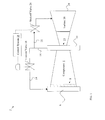
- FIG. 1 a schematic view of a system (e.g., a gas turbine inlet heating system) 2 is disclosed including a compressor 4 having an inlet bellmouth 6 adjacent to a set of inlet guide vanes (IGVs) 8 (shown in phantom as an internal component within compressor 4).
- the compressor 4 may further include an outlet 10 (e.g., an outlet manifold) fluidly connected to the inlet bellmouth 6 via a conduit 14, as described further herein.
- the conduit 14 can be coupled to the outlet 10 of the compressor 4.
- the conduit 14 can include a control valve 16, which is described further herein with respect to a control system 18 and control processes according to embodiments of the invention.
- the conduit 14 is for diverting a first portion of compressed air from the outlet 10 of the compressor 4 to the inlet bellmouth 6. That is, in contrast to conventional systems, the system 2 is capable of diverting exhaust compressed air from the outlet 10 of the compressor 4 directly to the IGVs 8, via the inlet bellmouth 6 (or, manifold). These conventional systems do not have the inlet bellmouth 6 as shown and described with reference to FIG. 1 .
- the system 2 can further include a control system 18 operably connected to the control valve 16.
- the control system 18 and control valve 16 can take any conventional forms capable of controlling the flow of fluid (e.g., air) through the conduit 14 (which may be a conventional conduit for carrying fluid).
- control valve 16 is a mechanically controlled valve
- the control system 18 may include mechanical components for opening and closing the control valve 16.
- the control system 18 can be an at least partially electrical system.
- the control system 18 and/or control valve 16 can be electro-mechanical devices.
- the control system 18 and/or control valve 16 can be at least partially software controlled.
- the control system 18 can be configured to provide instructions to the control valve 16 for providing a portion of the compressed air from the outlet 10 to the inlet bellmouth 6.
- the control system 18 can be further configured to monitor parameters of the turbine 20 and/or compressor 4 to determine an amount of air to be diverted via the conduit 14 (and/or bypass conduit 22). That is, the control system 18 may monitor temperature, flow rates, volumes, output, shaft speeds, etc. of one or more of the turbine 20 and/or compressor 4 to determine an amount of air to be diverted through conduit 14 and provided to inlet bellmouth 6. Further, the control system 18 may include or be operably connected with, a temperature sensor for determining an ambient temperature proximate to the compressor 4 and/or the turbine 20. This may allow the control system 18 to determine, e.g., whether anti-icing conditions are in effect.
- the inlet bellmouth 6 may be designed to receive compressed air exhaust from the outlet 10 directly from the conduit 14.
- the inlet bellmouth 6 may have an inner diameter of approximately 38 inches to approximately 66 inches. In other embodiments, the inlet bellmouth 6 may have an inner diameter of approximately 70 inches to approximately 95 inches.
- the compressor 4 can be coupled to a gas turbine 20, which may be a conventional gas turbine used for converting the motion of a gas across turbine blades within the turbine 20 into rotational motion in the turbine's shaft.
- the gas turbine 20 is configured to receive a second portion of compressed air from the outlet 10 of the compressor 4 via a second, or bypass conduit 22.
- the bypass conduit 22 can be connected with the first conduit 14 upstream of the control valve 16. That is, the bypass conduit 22 is connected to the first conduit 14 at a location closer to the outlet 10 of the compressor 4 than the location of the control valve 16 within the first conduit 14.
- the bypass conduit 22 is configured to receive a distinct portion of exhaust from the compressor 4 than the portion provided to the compressor's inlet bellmouth 6.
- the bypass conduit 22 is configured to supply bypass compressed air from the outlet 10 of the compressor 4 to a stage of the gas turbine 20, between the turbine's inlet 23 and its outlet 24. That is, the bypass conduit 22 is configured to supply bypass compressed air to a portion of the gas turbine downstream of the turbine inlet 23, in a lower-pressure section of the gas turbine 20.
- the flow of compressed air through the bypass conduit 22 can be controlled by a shut-off valve 26 (e.g., via the control system 18, or optionally, independently).
- the amount of compressed air extracted from the outlet 10 of the compressor 4 and provided to the inlet bellmouth 6 may be a function of the position of the control valve 16, compressor IGV's (8) angle position, and the compressor measured pressure ratio.
- the shut-off valve 26, together with control valve (16) can be controlled by the control system 18.
- aspects of the invention provide a control system 18 for actively controlling the control valve 16 (and/or the shut-off valve 26) to provide a predetermined portion of compressed air from the compressor outlet 10 to the IGVs 8, thereby allowing for heating of the compressor inlet bellmouth 6.
- This may allow for, among other things, anti-icing of the area around the compressor inlet bellmouth 6.
- the compressor inlet bellmouth 6 is designed to receive higher-pressure, higher temperature compressed air than in conventional systems. In some cases, this can require the compressor inlet bellmouth 6 to include a built-up, or reinforced portion configured to receive higher-pressure, higher-temperature compressed air.
- the inlet bellmouth 6 can include a flared-out or bell-shaped section having a greater inlet diameter than a portion of the compressor 4 surrounding the IGVs 8. That is, the inlet bellmouth 6 may have an inner diameter of such dimension that it can receive the higher-pressure compressed air from the conduit 14.
- the inlet bellmouth 6 may take a conventional manifold shape, which includes sections or steps that progressively narrow upon axial approach to the IGVs 8 from the inlet.
- the inlet bellmouth 6 can include several steps or sections along its inner surface for receiving air from the conduit 14.
- the system 2 shown and described herein can provide for performance gains in at least the following scenarios: a) Turndown operation, where the output of the turbine is being intentionally reduced; b) Anti-icing, where the ambient temperature conditions are cold enough to warrant heating of the compressor inlet (or, compressor skin); and c) Surge control, where unwanted variations in turbine output are being regulated.
- the system 2 shown and described herein can provide for a reduction in hardware components (e.g., additional piping, valves, etc.) while maintaining performance goals of the system.
- aspects of the invention allow for control of an amount of extracted compressed air (via control system 18) from the compressor outlet 10, which may allow for improved performance as compared to those conventional engine systems.
Landscapes
- Engineering & Computer Science (AREA)
- Chemical & Material Sciences (AREA)
- Combustion & Propulsion (AREA)
- Mechanical Engineering (AREA)
- General Engineering & Computer Science (AREA)
- Structures Of Non-Positive Displacement Pumps (AREA)
Applications Claiming Priority (1)
| Application Number | Priority Date | Filing Date | Title |
|---|---|---|---|
| US13/175,006 US8904747B2 (en) | 2011-07-01 | 2011-07-01 | Gas turbine inlet heating system |
Publications (2)
| Publication Number | Publication Date |
|---|---|
| EP2541022A2 true EP2541022A2 (de) | 2013-01-02 |
| EP2541022A3 EP2541022A3 (de) | 2016-08-24 |
Family
ID=46419978
Family Applications (1)
| Application Number | Title | Priority Date | Filing Date |
|---|---|---|---|
| EP12174324.9A Withdrawn EP2541022A3 (de) | 2011-07-01 | 2012-06-29 | Gasturbineneinlass-Heizsystem |
Country Status (3)
| Country | Link |
|---|---|
| US (1) | US8904747B2 (de) |
| EP (1) | EP2541022A3 (de) |
| CN (1) | CN102852644B (de) |
Cited By (3)
| Publication number | Priority date | Publication date | Assignee | Title |
|---|---|---|---|---|
| US9492780B2 (en) | 2014-01-16 | 2016-11-15 | Bha Altair, Llc | Gas turbine inlet gas phase contaminant removal |
| EP3379054A1 (de) * | 2017-03-20 | 2018-09-26 | General Electric Company | Systeme und verfahren zur steuerung der zapfluftwärme eines gasturbineneinlassfilters |
| US10502136B2 (en) | 2014-10-06 | 2019-12-10 | Bha Altair, Llc | Filtration system for use in a gas turbine engine assembly and method of assembling thereof |
Families Citing this family (9)
| Publication number | Priority date | Publication date | Assignee | Title |
|---|---|---|---|---|
| US20130193127A1 (en) * | 2012-01-26 | 2013-08-01 | General Electric Company | Combustion turbine inlet anti-icing resistive heating system |
| JP6039056B2 (ja) | 2012-04-02 | 2016-12-07 | パワーフェイズ・エルエルシー | ガスタービンエンジン用の圧縮空気注入システム方法および装置 |
| WO2014066276A2 (en) | 2012-10-26 | 2014-05-01 | Kraft Robert J | Gas turbine energy supplementing systems and heating systems, and methods of making and using the same |
| US20140123666A1 (en) * | 2012-11-07 | 2014-05-08 | General Electric Company | System to Improve Gas Turbine Output and Hot Gas Path Component Life Utilizing Humid Air for Nozzle Over Cooling |
| US9470150B2 (en) * | 2013-04-30 | 2016-10-18 | General Electric Company | Gas turbine power augmentation system |
| US10036321B2 (en) * | 2014-05-29 | 2018-07-31 | General Electric Company | Systems and methods for utilizing gas turbine compartment ventilation discharge air |
| US10054052B2 (en) * | 2015-07-07 | 2018-08-21 | United Technologies Corporation | Nacelle anti-ice system and method with equalized flow |
| US10876549B2 (en) | 2019-04-05 | 2020-12-29 | Pratt & Whitney Canada Corp. | Tandem stators with flow recirculation conduit |
| CN112196673A (zh) * | 2020-09-04 | 2021-01-08 | 华电电力科学研究院有限公司 | 一种用于联合循环发电厂的进气加热系统及其控制方法 |
Family Cites Families (17)
| Publication number | Priority date | Publication date | Assignee | Title |
|---|---|---|---|---|
| US2594118A (en) * | 1949-04-07 | 1952-04-22 | A V Roe Canada Ltd | Heated intake component for gas turbine engines |
| GB702931A (en) * | 1951-04-18 | 1954-01-27 | Bristol Aeroplane Co Ltd | Improvements in or relating to rotary machines comprising fluid compressing means |
| US3123283A (en) * | 1962-12-07 | 1964-03-03 | Anti-icing valve means | |
| US3919837A (en) | 1974-03-07 | 1975-11-18 | Sterling Drug Inc | Method and apparatus for startup of a wet air oxidation unit provided with rotating air compressors driven by rotating expanders |
| DE3333437A1 (de) * | 1983-09-16 | 1985-04-11 | MTU Motoren- und Turbinen-Union München GmbH, 8000 München | Einrichtung zur verdichterregelung von gasturbinentriebwerken |
| US4552579A (en) | 1983-12-07 | 1985-11-12 | Emhart Industries, Inc. | Glass forehearth |
| US5560195A (en) | 1995-02-13 | 1996-10-01 | General Electric Co. | Gas turbine inlet heating system using jet blower |
| US5763876A (en) | 1996-04-04 | 1998-06-09 | Mine Safety Appliances Company | Inlet heating device for ion mobility spectrometer |
| US5988283A (en) | 1997-07-02 | 1999-11-23 | Union Pacific Resources Company | Vertical combined production facility |
| US6027304A (en) * | 1998-05-27 | 2000-02-22 | General Electric Co. | High pressure inlet bleed heat system for the compressor of a turbine |
| US6226974B1 (en) | 1999-06-25 | 2001-05-08 | General Electric Co. | Method of operation of industrial gas turbine for optimal performance |
| GB2384058B (en) * | 2002-01-15 | 2005-11-30 | Rolls Royce Plc | Thrust correction |
| US7202447B2 (en) | 2004-04-02 | 2007-04-10 | Kingdon Charles J | Conveyor type oven |
| US7841186B2 (en) | 2007-01-31 | 2010-11-30 | Power Systems Mfg., Llc | Inlet bleed heat and power augmentation for a gas turbine engine |
| FR2920829B1 (fr) * | 2007-09-11 | 2014-03-21 | Ge Energy Products France Snc | Systeme d'admission d'air pour compresseur de turbine a gaz, et procede associe |
| US20100107594A1 (en) * | 2008-10-31 | 2010-05-06 | General Electric Company | Turbine integrated bleed system and method for a gas turbine engine |
| US8083466B2 (en) * | 2009-03-13 | 2011-12-27 | General Electric Company | Turbomachine inlet heating system |
-
2011
- 2011-07-01 US US13/175,006 patent/US8904747B2/en not_active Expired - Fee Related
-
2012
- 2012-06-29 EP EP12174324.9A patent/EP2541022A3/de not_active Withdrawn
- 2012-07-02 CN CN201210228520.9A patent/CN102852644B/zh not_active Expired - Fee Related
Non-Patent Citations (1)
| Title |
|---|
| None |
Cited By (4)
| Publication number | Priority date | Publication date | Assignee | Title |
|---|---|---|---|---|
| US9492780B2 (en) | 2014-01-16 | 2016-11-15 | Bha Altair, Llc | Gas turbine inlet gas phase contaminant removal |
| US10502136B2 (en) | 2014-10-06 | 2019-12-10 | Bha Altair, Llc | Filtration system for use in a gas turbine engine assembly and method of assembling thereof |
| EP3379054A1 (de) * | 2017-03-20 | 2018-09-26 | General Electric Company | Systeme und verfahren zur steuerung der zapfluftwärme eines gasturbineneinlassfilters |
| US10364754B2 (en) | 2017-03-20 | 2019-07-30 | General Electric Company | Systems and methods for controlling overboard bleed heat of a turbine inlet filter |
Also Published As
| Publication number | Publication date |
|---|---|
| US8904747B2 (en) | 2014-12-09 |
| CN102852644A (zh) | 2013-01-02 |
| EP2541022A3 (de) | 2016-08-24 |
| US20130000321A1 (en) | 2013-01-03 |
| CN102852644B (zh) | 2016-08-24 |
Similar Documents
| Publication | Publication Date | Title |
|---|---|---|
| US8904747B2 (en) | Gas turbine inlet heating system | |
| US8083495B2 (en) | Ejectors with separably secured nozzles, adjustable size nozzles, or adjustable size mixing tubes | |
| EP3318743B1 (de) | Zwischengekühlte gekühlte kühlungsintegrierte luftkreislaufmaschine | |
| US7946806B2 (en) | Gas turbine engine systems and related methods involving heat exchange | |
| EP3312091B1 (de) | Klimaregelungsanlage | |
| US9260974B2 (en) | System and method for active clearance control | |
| CN204152645U (zh) | 用于增强燃气涡轮机功率输出的系统及燃气涡轮机 | |
| US10634065B2 (en) | Engine bleed air system | |
| EP1998027B1 (de) | Gasturbine mit einem Plenum innerhalb einer Triebwerksgondel und einem Zapfluftsystem | |
| US9163562B2 (en) | Constant speed pump system for engine ECS loss elimination | |
| CN107120146B (zh) | 主动hpc间隙控制 | |
| US8356486B2 (en) | APU bleed valve with integral anti-surge port | |
| US10113484B2 (en) | High pressure exhaust muffling device with multiple sources | |
| JP2016537550A (ja) | ガスタービンエンジン用の圧縮機抽気及び周囲空気による冷却システム | |
| EP3321490A1 (de) | Turbogeneratorbasiertes zapfluftsystem | |
| US8371162B2 (en) | Apparatus and method for testing a compressor | |
| EP2982846A1 (de) | Turbomaschinensystem mit einer einlasszapfenlufterwärmung und verfahren zum betreiben einer turbomaschine in teillast | |
| EP2944772A1 (de) | Interner antifrostverteiler für gasturbinentriebwerk | |
| JP7429337B2 (ja) | 圧縮空気供給システム | |
| US12116930B2 (en) | Scoop for an aircraft turbine engine | |
| RU2573437C1 (ru) | Противообледенительная система газоперекачивающего агрегата с газотурбинным приводом | |
| US11236671B2 (en) | Air supply system for an aircraft | |
| WO2015033844A1 (ja) | タービン、ターボ過給機、内燃機関、及び船舶 | |
| EP3499005B1 (de) | Zapfluftejektor für eine gasturbine | |
| GB2399396A (en) | Bypass valve for a recuperator |
Legal Events
| Date | Code | Title | Description |
|---|---|---|---|
| PUAI | Public reference made under article 153(3) epc to a published international application that has entered the european phase |
Free format text: ORIGINAL CODE: 0009012 |
|
| AK | Designated contracting states |
Kind code of ref document: A2 Designated state(s): AL AT BE BG CH CY CZ DE DK EE ES FI FR GB GR HR HU IE IS IT LI LT LU LV MC MK MT NL NO PL PT RO RS SE SI SK SM TR |
|
| AX | Request for extension of the european patent |
Extension state: BA ME |
|
| PUAL | Search report despatched |
Free format text: ORIGINAL CODE: 0009013 |
|
| AK | Designated contracting states |
Kind code of ref document: A3 Designated state(s): AL AT BE BG CH CY CZ DE DK EE ES FI FR GB GR HR HU IE IS IT LI LT LU LV MC MK MT NL NO PL PT RO RS SE SI SK SM TR |
|
| AX | Request for extension of the european patent |
Extension state: BA ME |
|
| RIC1 | Information provided on ipc code assigned before grant |
Ipc: F02C 7/047 20060101AFI20160715BHEP Ipc: F02C 6/08 20060101ALI20160715BHEP |
|
| 17P | Request for examination filed |
Effective date: 20170224 |
|
| RBV | Designated contracting states (corrected) |
Designated state(s): AL AT BE BG CH CY CZ DE DK EE ES FI FR GB GR HR HU IE IS IT LI LT LU LV MC MK MT NL NO PL PT RO RS SE SI SK SM TR |
|
| STAA | Information on the status of an ep patent application or granted ep patent |
Free format text: STATUS: THE APPLICATION IS DEEMED TO BE WITHDRAWN |
|
| 18D | Application deemed to be withdrawn |
Effective date: 20190103 |