EP2541050A2 - Procédé pour l'identification de la fréquence principale de la transmission dans une éolienne - Google Patents
Procédé pour l'identification de la fréquence principale de la transmission dans une éolienne Download PDFInfo
- Publication number
- EP2541050A2 EP2541050A2 EP12004480A EP12004480A EP2541050A2 EP 2541050 A2 EP2541050 A2 EP 2541050A2 EP 12004480 A EP12004480 A EP 12004480A EP 12004480 A EP12004480 A EP 12004480A EP 2541050 A2 EP2541050 A2 EP 2541050A2
- Authority
- EP
- European Patent Office
- Prior art keywords
- wind turbine
- drive train
- signal
- generator speed
- speed
- Prior art date
- Legal status (The legal status is an assumption and is not a legal conclusion. Google has not performed a legal analysis and makes no representation as to the accuracy of the status listed.)
- Withdrawn
Links
- 238000000034 method Methods 0.000 title claims abstract description 26
- 238000013016 damping Methods 0.000 claims abstract description 13
- 238000001914 filtration Methods 0.000 claims abstract description 4
- 230000010355 oscillation Effects 0.000 description 4
- 230000003044 adaptive effect Effects 0.000 description 2
- 238000010586 diagram Methods 0.000 description 2
- 230000014509 gene expression Effects 0.000 description 2
- 238000004519 manufacturing process Methods 0.000 description 2
- 230000009471 action Effects 0.000 description 1
- 238000013459 approach Methods 0.000 description 1
- 238000004364 calculation method Methods 0.000 description 1
- 238000006243 chemical reaction Methods 0.000 description 1
- 238000011217 control strategy Methods 0.000 description 1
- 230000001276 controlling effect Effects 0.000 description 1
- 230000008878 coupling Effects 0.000 description 1
- 238000010168 coupling process Methods 0.000 description 1
- 238000005859 coupling reaction Methods 0.000 description 1
- 230000001934 delay Effects 0.000 description 1
- 238000012986 modification Methods 0.000 description 1
- 230000004048 modification Effects 0.000 description 1
- 238000012545 processing Methods 0.000 description 1
- 230000001105 regulatory effect Effects 0.000 description 1
- 230000004044 response Effects 0.000 description 1
- 238000010408 sweeping Methods 0.000 description 1
- 238000012546 transfer Methods 0.000 description 1
Images
Classifications
-
- F—MECHANICAL ENGINEERING; LIGHTING; HEATING; WEAPONS; BLASTING
- F03—MACHINES OR ENGINES FOR LIQUIDS; WIND, SPRING, OR WEIGHT MOTORS; PRODUCING MECHANICAL POWER OR A REACTIVE PROPULSIVE THRUST, NOT OTHERWISE PROVIDED FOR
- F03D—WIND MOTORS
- F03D7/00—Controlling wind motors
- F03D7/02—Controlling wind motors the wind motors having rotation axis substantially parallel to the air flow entering the rotor
- F03D7/0296—Controlling wind motors the wind motors having rotation axis substantially parallel to the air flow entering the rotor to prevent, counteract or reduce noise emissions
-
- F—MECHANICAL ENGINEERING; LIGHTING; HEATING; WEAPONS; BLASTING
- F03—MACHINES OR ENGINES FOR LIQUIDS; WIND, SPRING, OR WEIGHT MOTORS; PRODUCING MECHANICAL POWER OR A REACTIVE PROPULSIVE THRUST, NOT OTHERWISE PROVIDED FOR
- F03D—WIND MOTORS
- F03D17/00—Monitoring or testing of wind motors, e.g. diagnostics
-
- F—MECHANICAL ENGINEERING; LIGHTING; HEATING; WEAPONS; BLASTING
- F05—INDEXING SCHEMES RELATING TO ENGINES OR PUMPS IN VARIOUS SUBCLASSES OF CLASSES F01-F04
- F05B—INDEXING SCHEME RELATING TO WIND, SPRING, WEIGHT, INERTIA OR LIKE MOTORS, TO MACHINES OR ENGINES FOR LIQUIDS COVERED BY SUBCLASSES F03B, F03D AND F03G
- F05B2270/00—Control
- F05B2270/30—Control parameters, e.g. input parameters
- F05B2270/334—Vibration measurements
-
- Y—GENERAL TAGGING OF NEW TECHNOLOGICAL DEVELOPMENTS; GENERAL TAGGING OF CROSS-SECTIONAL TECHNOLOGIES SPANNING OVER SEVERAL SECTIONS OF THE IPC; TECHNICAL SUBJECTS COVERED BY FORMER USPC CROSS-REFERENCE ART COLLECTIONS [XRACs] AND DIGESTS
- Y02—TECHNOLOGIES OR APPLICATIONS FOR MITIGATION OR ADAPTATION AGAINST CLIMATE CHANGE
- Y02E—REDUCTION OF GREENHOUSE GAS [GHG] EMISSIONS, RELATED TO ENERGY GENERATION, TRANSMISSION OR DISTRIBUTION
- Y02E10/00—Energy generation through renewable energy sources
- Y02E10/70—Wind energy
- Y02E10/72—Wind turbines with rotation axis in wind direction
Definitions
- the invention relates to the damping of the drive train vibrations in wind turbines and, more in particular, to the identification of the drive train main frequency vibration.
- Wind turbines are devices that convert mechanical wind energy to electrical energy.
- a typical wind turbine includes a nacelle mounted on a tower housing a drive train for transmitting the rotation of a rotor to an electric generator and other components such as a yaw drive which orientates the wind turbine, several actuators and sensors and a brake.
- the rotor supports a number of blades that capture the kinetic energy of the wind and cause the drive train rotational motion.
- the rotor blades have an aerodynamic shape such that when a wind blows across the surface of the blade, a lift force is generated causing the rotation of a shaft which is connected -directly or through a gearing arrangement-to the electrical generator located inside the nacelle.
- the amount of energy produced by wind turbines depends on the rotor blade sweeping surface that receives the action from the wind and consequently increasing the length of the blades leads normally to an increase of the power output of the wind turbine.
- the blades are controlled to stay in autorotation regime during normal phase, and its attitude depends on the wind intensity.
- the dynamic coupling of the first symmetric in-plane mode of the 3 bladed rotor with the drive-train main frequency results in a coupled mode which is practically undamped in the wind turbine operation.
- This coupled mode may even be excited when operating at nominal power for high wind speeds leading to unaffordable loading on the drive-train.
- a wind turbine control operation without considering such dynamics can easily lead to damaging levels of fatigue loading on the gearbox.
- US 2006/0066111 discloses a vibration damping technique for variable speed wind turbines that not only aids damping of drive train vibrations caused by variation in wind speed, but also mitigates tower loads caused by side-to-side oscillations of the tower. Further, the technique advantageously reduces power fluctuations of the generator coupled to the wind turbine rotor. Said vibrations are determined as a function of the rotor speed using Fourier transforms in real-time operation.
- a drawback of said proposal regarding particularly to the identification of the drive train vibrations is that the Fourier transforms require time windows of data of a certain size that may cause important delays in the processing of the generator speed signal.
- the present invention focuses on finding a solution for said drawback.
- An object of the present invention is to provide an online identification of the drive train main frequency in a wind turbine for an enhancement of the drive train damping.
- this and other objects are met by a method for the identification in operation of the drive train main vibration frequency of a wind turbine, comprising online steps of: a) obtaining a input signal r of the generator speed ⁇ , b) filtering the generator speed input signal r for obtaining a generator speed signal r1 in a suitable band for representing the oscillating signal o comprised in the input signal r of the generator speed ⁇ ; c) extracting the drive train main vibration frequency f from said filtered signal r1.
- said suitable band in said step b) is the better band, among a predetermined number of bands, for taking into account the oscillating signal o comprised in the input signal r of the generator speed ⁇ and, particularly, the band that, representing said input signal r as a filtered signal s plus an oscillating signal o of a frequency fi + ⁇ fi, being fi the central frequency of the each band, achieves a minimum value of ⁇ fi.
- the method also includes a first step where said input signal r is obtained as a filtered signal of the raw generator speed signal r0 in a predetermined frequency interval, preferably in the interval 1-2,5 Hz.
- a predetermined frequency interval preferably in the interval 1-2,5 Hz.
- said predetermined number of bands is five, covering in equally dimensioned intervals a frequency range between 1,45-2,05 Hz.
- a suitable number of bands for providing a good response time for the calculation of the drive train main frequency.
- the above-mentioned objects are met by a method of damping the drive train vibrations of a wind turbine comprising steps of setting the generator torque reference Tr ref as a function of the generator speed ⁇ and of the drive train main vibration frequency f identified by the above-mentioned method.
- a wind turbine control system connected to measuring devices of, at least, wind speed V , generator speed ⁇ , pitch angle ⁇ of each blade, power P and to, at least, pitch and torque control actuators; the wind turbine control system being arranged for performing a regulation of the wind turbine according to a predetermined power curve 25 for wind speeds below the cut-out wind speed V out ; the wind turbine control system being also arranged for implementing the above-mentioned damping method.
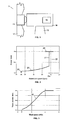
- a typical wind turbine 11 comprises a tower 13 supporting a nacelle 18 housing a generator 19 for converting the rotational energy of the wind turbine rotor into electrical energy.
- the wind turbine rotor comprises a rotor hub 15 and, typically, three blades 17.
- the rotor hub 15 is connected either directly or through a gearbox to the generator 19 of the wind turbine for transferring the torque generated by the rotor 15 to the generator 19 and increase the shaft speed in order to achieve a suitable rotational speed of the generator rotor.
- the power output from a modern wind turbine is typically controlled by means of a control system for regulating the pitch angle of the rotor blades and the generator torque.
- the rotor rotational speed and power output of the wind turbine can hereby be initially controlled e.g. before a transfer to a utility grid through a converter.
- variable speed wind turbines The basic aim of the methods of operation of variable speed wind turbines is to achieve an operation at the ideal aerodynamic output for as much time as possible.
- the kinetic energy associated with the incoming wind depends on the area swept by the rotor blades, on the air density and on the cube of the wind speed and it is considered that wind turbines can extract up to 59% of this energy. Accordingly, the capacity of each wind turbine to approach this limit is represented by the so-called power coefficient Cp which is determined by its aerodynamic characteristics, particularly by its tip-speed ratio ⁇ which is defined as the relationship between the tangential speed of the blade tip and the speed of the incident wind. If this ratio is kept at its optimal value, so that the rotor speed follows the wind speed, the maximum power coefficient Cp of the wind turbine is obtained, achieving an extremely efficient energy conversion.
- control strategy generally used in variable speed wind turbines is based on electrically adjusting the generator's torque to achieve the maximum output and this is carried out using a controller which receives signals indicating the speed of the generator and the power produced by the generator and which provides a torque reference signal to the converter to obtain the required power.
- the wind turbine controller uses a curve which defines the desired functional relationship between power and generator speed to achieve ideal output.
- the Power vs. Generator speed curve shown in Figure 2 comprises a first sub-nominal zone 23 where the wind speed attains the minimum level for starting the wind turbine operation. In this zone, the wind turbine control is limited since the wind turbine can not capture the maximum energy.
- the second sub-nominal zone 25 corresponds to wind speeds in a certain range where generator speed increases and the turbine is running with optimum power coefficient Cp.
- the third sub-nominal zone 27 corresponds to wind speeds in a certain range where the generator speed is kept constant at the nominal generator speed ⁇ n while power increases up to the nominal power Pwn. Within this zone the pitch angle is fixed and the generator speed is controlled via torque. At the nominal zone 29 the full load wind turbine operation at nominal power Pwn takes place under pitch control to avoid overloads.
- the resulting average power curve will be curve 22 in Figure 3 that shows that the power production P increases from a minimum wind speed V 2 to the nominal wind speed V n and then remain constant in the nominal power value Pwn up to the cut-out wind speed.
- This curve defines the desired functional relationship between power and speed to achieve ideal output and therefore the wind turbine control system shall be accordingly arranged.
- a control unit receives input data such as wind speed V, generator speed ⁇ , pitch angle ⁇ , power Pw from well known measuring devices and send output data ⁇ ref . Tr ref to, respectively, the pitch actuator system for changing the angular position of the blades 17 and to a generator command unit for changing the reference for the power production.
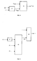
- the basic inputs to a torque controller 33 provided with means for damping the drive train vibrations are a torque demand Tr dem according to the Power vs. Generator speed curve 21 and a torque Tr dam according to the damping needs of the drive train determined in block 31 as a function of generator speed ⁇ and of the drive train main frequency f .
- the output is a torque reference Tr ref for the generator command unit.
- This invention is focused in the online identification of the drive train main frequency f when the wind turbine is in operation and comprises the following steps in a preferred embodiment (see Figure 5 ).
- the raw generator speed signal r0 provided by the above-mentioned measuring device of the generator speed ⁇ is filtered in block 41 for obtaining an input signal r in a predetermined frequency interval, preferably a 1-2,5 Hz interval, to avoid signal perturbations.
- the better frequency band (between a predetermined number of bands defined by the variable P2), defined by the variable P3, representing the oscillating signal o comprised in the input signal r of the generator speed ⁇ is obtained in block 43.
- the input signal r can be represented in each of said bands as a filtered signal s plus an oscillation signal o with unknown amplitude and phase and with a known frequency with a certain uncertainty (the central frequency of each subband plus an offset).
- ⁇ ⁇ and ⁇ ⁇ are the step size to define the convergence time and the stability of the algorithm. They must be experimentally calculated. All the parameters needed for this step are defined in variable P1.
- the band where the oscillation is occurring is determined calculating the ⁇ f in each band.
- the minimum ⁇ f will determine the band to be filtered.
- Said filtering is done in a third step in block 45 obtaining the signal r1 needed for obtaining the drive train main frequency f.
Landscapes
- Engineering & Computer Science (AREA)
- Life Sciences & Earth Sciences (AREA)
- Sustainable Development (AREA)
- Sustainable Energy (AREA)
- Chemical & Material Sciences (AREA)
- Combustion & Propulsion (AREA)
- Mechanical Engineering (AREA)
- General Engineering & Computer Science (AREA)
- Wind Motors (AREA)
- Control Of Eletrric Generators (AREA)
Applications Claiming Priority (1)
| Application Number | Priority Date | Filing Date | Title |
|---|---|---|---|
| ES201100728A ES2398051B1 (es) | 2011-06-28 | 2011-06-28 | Un método para la identificación de la frecuencia principal del tren de potencia de un aerogenerador. |
Publications (2)
| Publication Number | Publication Date |
|---|---|
| EP2541050A2 true EP2541050A2 (fr) | 2013-01-02 |
| EP2541050A3 EP2541050A3 (fr) | 2014-08-06 |
Family
ID=46516482
Family Applications (1)
| Application Number | Title | Priority Date | Filing Date |
|---|---|---|---|
| EP12004480.5A Withdrawn EP2541050A3 (fr) | 2011-06-28 | 2012-06-14 | Procédé pour l'identification de la fréquence principale de la transmission dans une éolienne |
Country Status (3)
| Country | Link |
|---|---|
| US (1) | US9273671B2 (fr) |
| EP (1) | EP2541050A3 (fr) |
| ES (1) | ES2398051B1 (fr) |
Cited By (3)
| Publication number | Priority date | Publication date | Assignee | Title |
|---|---|---|---|---|
| CN106089581A (zh) * | 2015-03-13 | 2016-11-09 | 通用电气公司 | 用于风轮机的可变末梢速度比控制的系统及方法 |
| EP3734833A1 (fr) * | 2019-05-02 | 2020-11-04 | Siemens Gamesa Renewable Energy A/S | Procédé de fonctionnement d'une machine électrique à l'aide d'une courbe de capacité dynamique |
| CN117332602A (zh) * | 2023-10-18 | 2024-01-02 | 华北电力大学 | 一种风力发电机一次调频模拟方法及装置 |
Families Citing this family (5)
| Publication number | Priority date | Publication date | Assignee | Title |
|---|---|---|---|---|
| ES2396504B1 (es) * | 2010-10-29 | 2014-01-02 | Gamesa Innovation & Technology, S.L. | Aerogenerador con un control activo del ángulo de paso de las palas durante una situación de marcha en vacío. |
| CN105863971A (zh) * | 2016-06-27 | 2016-08-17 | 国电联合动力技术有限公司 | 一种适用于风力发电机组塔筒避振的虚拟质量控制方法 |
| US11635062B2 (en) | 2018-11-07 | 2023-04-25 | General Electric Renovables Espana, S.L. | Wind turbine and method to determine modal characteristics of the wind turbine in a continuous manner |
| EP3667074A1 (fr) * | 2018-12-13 | 2020-06-17 | Siemens Gamesa Renewable Energy A/S | Dispositif et procédé d'amortissement des mouvements avant et arrière d'une tour d'éolienne |
| CN113266538B (zh) * | 2021-05-31 | 2022-03-22 | 明阳智慧能源集团股份公司 | 一种海上风电塔架与传动链模态频率自动识别方法及系统 |
Citations (2)
| Publication number | Priority date | Publication date | Assignee | Title |
|---|---|---|---|---|
| US20060066111A1 (en) | 2004-09-30 | 2006-03-30 | Shashikanth Suryanarayanan | Vibration damping system and method for variable speed wind turbines |
| US20110140425A1 (en) * | 2010-08-25 | 2011-06-16 | Martin Staedler | Method and System For Controlling Wind Turbine Rotational Speed |
Family Cites Families (8)
| Publication number | Priority date | Publication date | Assignee | Title |
|---|---|---|---|---|
| AU2046499A (en) * | 1998-01-14 | 1999-08-02 | Dancontrol Engineering A/S | Method for measuring and controlling oscillations in a wind turbine |
| JP4007268B2 (ja) * | 2003-07-22 | 2007-11-14 | 株式会社日立製作所 | 風力発電装置 |
| US7495403B2 (en) * | 2004-03-30 | 2009-02-24 | Continental Automotive Systems Us, Inc. | Method, apparatus and article for vibration compensation in electric drivetrains |
| KR100608109B1 (ko) * | 2004-06-28 | 2006-08-02 | 삼성전자주식회사 | 이동통신 시스템에서 도플러 주파수 및 단말기의 이동속도 계산 장치 및 방법 |
| CN101535634A (zh) * | 2006-10-02 | 2009-09-16 | 维斯塔斯风力系统有限公司 | 风轮机,通过改变叶片桨距减弱风轮机的一个或多个叶片中边沿振荡的方法及其使用 |
| DE102007019907B4 (de) * | 2007-04-27 | 2009-04-30 | Nordex Energy Gmbh | Vorrichtung zur aktiven Dämpfung eines Triebstrangs bei einer Windenergieanlage |
| DK200701144A (da) * | 2007-08-13 | 2009-02-14 | Siemens Wind Power As | Monitoring of blade frequencies of a wind turbine |
| EP2072975A1 (fr) * | 2007-12-19 | 2009-06-24 | Siemens Aktiengesellschaft | Procédé et appareil pour la surveillance de la condition automatique à base de vibrations d'une éolienne |
-
2011
- 2011-06-28 ES ES201100728A patent/ES2398051B1/es not_active Expired - Fee Related
-
2012
- 2012-06-14 EP EP12004480.5A patent/EP2541050A3/fr not_active Withdrawn
- 2012-06-26 US US13/532,987 patent/US9273671B2/en not_active Expired - Fee Related
Patent Citations (2)
| Publication number | Priority date | Publication date | Assignee | Title |
|---|---|---|---|---|
| US20060066111A1 (en) | 2004-09-30 | 2006-03-30 | Shashikanth Suryanarayanan | Vibration damping system and method for variable speed wind turbines |
| US20110140425A1 (en) * | 2010-08-25 | 2011-06-16 | Martin Staedler | Method and System For Controlling Wind Turbine Rotational Speed |
Cited By (10)
| Publication number | Priority date | Publication date | Assignee | Title |
|---|---|---|---|---|
| CN106089581A (zh) * | 2015-03-13 | 2016-11-09 | 通用电气公司 | 用于风轮机的可变末梢速度比控制的系统及方法 |
| US10473088B2 (en) | 2015-03-13 | 2019-11-12 | General Electric Company | System and method for variable tip-speed-ratio control of a wind turbine |
| CN106089581B (zh) * | 2015-03-13 | 2020-02-07 | 通用电气公司 | 用于风轮机的可变末梢速度比控制的系统及方法 |
| EP3734833A1 (fr) * | 2019-05-02 | 2020-11-04 | Siemens Gamesa Renewable Energy A/S | Procédé de fonctionnement d'une machine électrique à l'aide d'une courbe de capacité dynamique |
| WO2020221541A1 (fr) * | 2019-05-02 | 2020-11-05 | Siemens Gamesa Renewable Energy A/S | Procédé d'utilisation d'une machine électrique à l'aide d'une courbe de capacité dynamique |
| CN114026778A (zh) * | 2019-05-02 | 2022-02-08 | 西门子歌美飒可再生能源公司 | 用于使用动态能力曲线来操作电机的方法 |
| US11739730B2 (en) | 2019-05-02 | 2023-08-29 | Siemens Gamesa Renewable Energy A/S | Method for operating an electric machine using a dynamic capacity curve |
| CN114026778B (zh) * | 2019-05-02 | 2025-08-05 | 西门子歌美飒可再生能源公司 | 用于使用动态能力曲线来操作电机的方法 |
| CN117332602A (zh) * | 2023-10-18 | 2024-01-02 | 华北电力大学 | 一种风力发电机一次调频模拟方法及装置 |
| CN117332602B (zh) * | 2023-10-18 | 2024-04-19 | 华北电力大学 | 一种风力发电机一次调频模拟方法及装置 |
Also Published As
| Publication number | Publication date |
|---|---|
| US20130001945A1 (en) | 2013-01-03 |
| ES2398051A2 (es) | 2013-03-13 |
| EP2541050A3 (fr) | 2014-08-06 |
| ES2398051R1 (es) | 2013-11-28 |
| US9273671B2 (en) | 2016-03-01 |
| ES2398051B1 (es) | 2014-09-05 |
Similar Documents
| Publication | Publication Date | Title |
|---|---|---|
| US9273671B2 (en) | Method for the identification of the drive train main frequency in a wind turbine | |
| CN101520027B (zh) | 用于风力涡轮机的可变叶尖速比跟踪控制 | |
| CN101688518B (zh) | 可变速度风力涡轮机、谐振控制系统、运行可变速度风力涡轮机的方法、可变速度风力涡轮机中方法的使用以及谐振控制系统的使用 | |
| CN103026059B (zh) | 风力涡轮机的控制方法 | |
| EP3892851B1 (fr) | Système et procédé de commande sous charge extrême améliorée pour pales de rotor d'éolienne | |
| EP2492499B1 (fr) | Procédés de commande d'aérogénérateurs permettant d'améliorer la production d'énergie | |
| EP2336558B1 (fr) | Procédé d'opération d'une éolienne à vitesse variable | |
| EP3575595B1 (fr) | Procédé et systèmes de fonctionnement d'une éolienne | |
| CN102803716B (zh) | 风力发电装置的控制装置、风力发电装置及风力发电装置的控制方法 | |
| US8677810B2 (en) | Methods for monitoring wind turbines | |
| EP2655876B1 (fr) | Supervision de l'instabilité du dispositif de commande dans une éolienne | |
| EP2113659B1 (fr) | Procédé de fonctionnement d'éolienne qui minimise les oscillations de la tour | |
| US20100078939A1 (en) | System and method for controlling a wind turbine during loss of grid power and changing wind conditions | |
| US20090146424A1 (en) | System and method for controlling a wind power plant | |
| EP2966297A1 (fr) | Système de génération d'énergie éolienne | |
| EP3032095A1 (fr) | Procédé de fonctionnement d'une éolienne et éoliennes | |
| US11608811B2 (en) | System and method for mitigating loads acting on a rotor blade of a wind turbine | |
| EP3812577B1 (fr) | Système et procédé pour atténuer les charges agissant sur une pale de rotor d'une éolienne | |
| KR101363516B1 (ko) | 풍력 발전기용 발전기의 제어 방법 | |
| US10704533B2 (en) | Wind turbine power generating apparatus and method of operating the same | |
| US20240102448A1 (en) | Method and system for damping a wind turbine tower |
Legal Events
| Date | Code | Title | Description |
|---|---|---|---|
| PUAI | Public reference made under article 153(3) epc to a published international application that has entered the european phase |
Free format text: ORIGINAL CODE: 0009012 |
|
| AK | Designated contracting states |
Kind code of ref document: A2 Designated state(s): AL AT BE BG CH CY CZ DE DK EE ES FI FR GB GR HR HU IE IS IT LI LT LU LV MC MK MT NL NO PL PT RO RS SE SI SK SM TR |
|
| AX | Request for extension of the european patent |
Extension state: BA ME |
|
| PUAL | Search report despatched |
Free format text: ORIGINAL CODE: 0009013 |
|
| AK | Designated contracting states |
Kind code of ref document: A3 Designated state(s): AL AT BE BG CH CY CZ DE DK EE ES FI FR GB GR HR HU IE IS IT LI LT LU LV MC MK MT NL NO PL PT RO RS SE SI SK SM TR |
|
| AX | Request for extension of the european patent |
Extension state: BA ME |
|
| RIC1 | Information provided on ipc code assigned before grant |
Ipc: F03D 11/00 20060101ALI20140703BHEP Ipc: F03D 7/02 20060101AFI20140703BHEP |
|
| 17P | Request for examination filed |
Effective date: 20150204 |
|
| RBV | Designated contracting states (corrected) |
Designated state(s): AL AT BE BG CH CY CZ DE DK EE ES FI FR GB GR HR HU IE IS IT LI LT LU LV MC MK MT NL NO PL PT RO RS SE SI SK SM TR |
|
| 17Q | First examination report despatched |
Effective date: 20170317 |
|
| RAP1 | Party data changed (applicant data changed or rights of an application transferred) |
Owner name: SIEMENS GAMESA RENEWABLE ENERGY INNOVATION & TECHN |
|
| STAA | Information on the status of an ep patent application or granted ep patent |
Free format text: STATUS: THE APPLICATION IS DEEMED TO BE WITHDRAWN |
|
| 18D | Application deemed to be withdrawn |
Effective date: 20200603 |