EP2541071A2 - Agencement de soupapes pour un système de commande hydraulique - Google Patents
Agencement de soupapes pour un système de commande hydraulique Download PDFInfo
- Publication number
- EP2541071A2 EP2541071A2 EP12004137A EP12004137A EP2541071A2 EP 2541071 A2 EP2541071 A2 EP 2541071A2 EP 12004137 A EP12004137 A EP 12004137A EP 12004137 A EP12004137 A EP 12004137A EP 2541071 A2 EP2541071 A2 EP 2541071A2
- Authority
- EP
- European Patent Office
- Prior art keywords
- connection
- valve
- port
- consumer
- pressure
- Prior art date
- Legal status (The legal status is an assumption and is not a legal conclusion. Google has not performed a legal analysis and makes no representation as to the accuracy of the status listed.)
- Granted
Links
Images

Classifications
-
- F—MECHANICAL ENGINEERING; LIGHTING; HEATING; WEAPONS; BLASTING
- F15—FLUID-PRESSURE ACTUATORS; HYDRAULICS OR PNEUMATICS IN GENERAL
- F15B—SYSTEMS ACTING BY MEANS OF FLUIDS IN GENERAL; FLUID-PRESSURE ACTUATORS, e.g. SERVOMOTORS; DETAILS OF FLUID-PRESSURE SYSTEMS, NOT OTHERWISE PROVIDED FOR
- F15B11/00—Servomotor systems without provision for follow-up action; Circuits therefor
- F15B11/006—Hydraulic "Wheatstone bridge" circuits, i.e. with four nodes, P-A-T-B, and on-off or proportional valves in each link
-
- F—MECHANICAL ENGINEERING; LIGHTING; HEATING; WEAPONS; BLASTING
- F15—FLUID-PRESSURE ACTUATORS; HYDRAULICS OR PNEUMATICS IN GENERAL
- F15B—SYSTEMS ACTING BY MEANS OF FLUIDS IN GENERAL; FLUID-PRESSURE ACTUATORS, e.g. SERVOMOTORS; DETAILS OF FLUID-PRESSURE SYSTEMS, NOT OTHERWISE PROVIDED FOR
- F15B2211/00—Circuits for servomotor systems
- F15B2211/20—Fluid pressure source, e.g. accumulator or variable axial piston pump
- F15B2211/205—Systems with pumps
- F15B2211/20576—Systems with pumps with multiple pumps
- F15B2211/20592—Combinations of pumps for supplying high and low pressure
-
- F—MECHANICAL ENGINEERING; LIGHTING; HEATING; WEAPONS; BLASTING
- F15—FLUID-PRESSURE ACTUATORS; HYDRAULICS OR PNEUMATICS IN GENERAL
- F15B—SYSTEMS ACTING BY MEANS OF FLUIDS IN GENERAL; FLUID-PRESSURE ACTUATORS, e.g. SERVOMOTORS; DETAILS OF FLUID-PRESSURE SYSTEMS, NOT OTHERWISE PROVIDED FOR
- F15B2211/00—Circuits for servomotor systems
- F15B2211/30—Directional control
- F15B2211/305—Directional control characterised by the type of valves
- F15B2211/3056—Assemblies of multiple valves
- F15B2211/30565—Assemblies of multiple valves having multiple valves for a single output member, e.g. for creating higher valve function by use of multiple valves like two 2/2-valves replacing a 5/3-valve
- F15B2211/30575—Assemblies of multiple valves having multiple valves for a single output member, e.g. for creating higher valve function by use of multiple valves like two 2/2-valves replacing a 5/3-valve in a Wheatstone Bridge arrangement (also half bridges)
-
- F—MECHANICAL ENGINEERING; LIGHTING; HEATING; WEAPONS; BLASTING
- F15—FLUID-PRESSURE ACTUATORS; HYDRAULICS OR PNEUMATICS IN GENERAL
- F15B—SYSTEMS ACTING BY MEANS OF FLUIDS IN GENERAL; FLUID-PRESSURE ACTUATORS, e.g. SERVOMOTORS; DETAILS OF FLUID-PRESSURE SYSTEMS, NOT OTHERWISE PROVIDED FOR
- F15B2211/00—Circuits for servomotor systems
- F15B2211/40—Flow control
- F15B2211/41—Flow control characterised by the positions of the valve element
- F15B2211/413—Flow control characterised by the positions of the valve element the positions being continuously variable, e.g. as realised by proportional valves
-
- F—MECHANICAL ENGINEERING; LIGHTING; HEATING; WEAPONS; BLASTING
- F15—FLUID-PRESSURE ACTUATORS; HYDRAULICS OR PNEUMATICS IN GENERAL
- F15B—SYSTEMS ACTING BY MEANS OF FLUIDS IN GENERAL; FLUID-PRESSURE ACTUATORS, e.g. SERVOMOTORS; DETAILS OF FLUID-PRESSURE SYSTEMS, NOT OTHERWISE PROVIDED FOR
- F15B2211/00—Circuits for servomotor systems
- F15B2211/40—Flow control
- F15B2211/415—Flow control characterised by the connections of the flow control means in the circuit
- F15B2211/41563—Flow control characterised by the connections of the flow control means in the circuit being connected to a pressure source and a return line
-
- F—MECHANICAL ENGINEERING; LIGHTING; HEATING; WEAPONS; BLASTING
- F15—FLUID-PRESSURE ACTUATORS; HYDRAULICS OR PNEUMATICS IN GENERAL
- F15B—SYSTEMS ACTING BY MEANS OF FLUIDS IN GENERAL; FLUID-PRESSURE ACTUATORS, e.g. SERVOMOTORS; DETAILS OF FLUID-PRESSURE SYSTEMS, NOT OTHERWISE PROVIDED FOR
- F15B2211/00—Circuits for servomotor systems
- F15B2211/40—Flow control
- F15B2211/45—Control of bleed-off flow, e.g. control of bypass flow to the return line
-
- F—MECHANICAL ENGINEERING; LIGHTING; HEATING; WEAPONS; BLASTING
- F15—FLUID-PRESSURE ACTUATORS; HYDRAULICS OR PNEUMATICS IN GENERAL
- F15B—SYSTEMS ACTING BY MEANS OF FLUIDS IN GENERAL; FLUID-PRESSURE ACTUATORS, e.g. SERVOMOTORS; DETAILS OF FLUID-PRESSURE SYSTEMS, NOT OTHERWISE PROVIDED FOR
- F15B2211/00—Circuits for servomotor systems
- F15B2211/70—Output members, e.g. hydraulic motors or cylinders or control therefor
- F15B2211/705—Output members, e.g. hydraulic motors or cylinders or control therefor characterised by the type of output members or actuators
- F15B2211/7051—Linear output members
- F15B2211/7053—Double-acting output members
Definitions
- the present invention relates to a valve assembly for a hydraulic control system for controlling a hydraulic consumer, having a pressure port for connection to a pressure supply, a tank port for connection to a return line, and two load ports for connection to the terminals of the hydraulic consumer.
- valve assemblies are commonly used in hydraulic control systems to control the supply to and drain from a hydraulic consumer.
- a 4/3-way proportional valve is usually used to control the movement of the hydraulic consumer in both directions.
- the present invention shows a valve assembly for a hydraulic control system for driving a hydraulic consumer, with a pressure port for connection to a pressure supply, a tank port for connection to a return line, and two load ports for connection to the terminals of the hydraulic consumer. At least two separate valves are provided for controlling the connection of the two consumer connections with pressure connection and tank connection.
- the valve assembly further comprises a valve for connection of pressure port and tank port.
- valve according to the invention for connecting the pressure connection and the tank connection, an "open center" function is made possible, which connects the pressure connection and tank connection as long as there is no volumetric flow demand for the hydraulic consumer.
- This allows a more flexible use of the invention Valve arrangement and improves the drive options. In particular, it is possible to connect several valve assemblies in series.
- the system of resolved control edges also makes it possible to control the individual control edges separately from each other and / or to design or dimension different to adapt the cross sections and to minimize the flow losses.
- valves for connection of pressure connection and tank connection are at least partially separately and optionally controlled differently.
- valves for connecting the pressure connection and the tank connection, in particular differently dimensioned valves.
- valve for connecting pressure port and tank port is designed as a separate valve.
- the "open center" function is thus not integrated in the valves for connecting the two consumer connections with pressure connection and tank connection, but executed separately.
- a 2/2-way valve can be used for the valve for connecting the pressure connection and tank connection.
- the present invention is advantageously used for controlling hydraulic consumers with two directions of movement.
- the valve arrangement is designed so that it can connect both consumer connections with the pressure connection or the tank connection, depending on the desired direction of movement.
- the present invention is used in valve assemblies with resolved control edges, in which for connecting the first consumer terminal another valve is used with the pressure connection than for connecting the second consumer connection to the tank connection and / or wherein a second valve is used to connect the second consumer connection to the pressure connection than to connect the first consumer connection to the tank connection.
- a different valve is used to connect the first consumer port to the pressure port than to connect the second consumer port to the pressure port and / or to connect the first consumer port to the tank port, a different valve is used to connect the second consumer port with the tank connection.
- valves are used for all connections between the two consumer connections and pressure connection and tank connection, that is, a total of four valves for connecting the two consumer connections with pressure connection and tank connection.
- 2/2-way valves can be used according to the invention for the valves for connecting the consumer connections with pressure connection and tank connection.
- valves can be used to connect the consumer connections with pressure connection and tank connection. If a consumer is to be controlled with two directions of movement, two 3/3-way valves are advantageously used for this purpose.
- the valve arrangement according to the invention comprises a control which closes the valve for connection of pressure port and tank port when the connection between one of the consumer ports and the pressure port is opened. Conversely, when all connections between one of the consumer ports and the pressure port are closed, the controller opens the pressure port and tank port connection valve. Furthermore, the controller can equally account for the connections between the load ports and the tank port.
- the actuation of the valves of the valve arrangement according to the invention can be carried out both hydraulically, as well as electrically.
- control of the valves for connection of the consumer connections with pressure connection and tank connection and / or the valve for connection of pressure connection and tank connection takes place hydraulically.
- the valves for connection of the consumer connections with pressure connection and tank connection and / or the valve for connection of pressure connection and tank connection can be controlled in each case via a separate valve associated therewith.
- a separate valve associated therewith for example, in each case a 3/3-way valve can be used.
- the valves for connecting the consumer connections with pressure connection and tank connection are each controlled via a separate valve associated with them.
- the valve for connection of pressure connection and tank connection is controlled via a separate valve associated with it.
- valves for connecting the consumer connections with pressure connection and tank connection and / or the valve for connection of pressure connection and tank connection are at least partially controlled jointly.
- valves for connection of the consumer connections with pressure connection and tank connection can be controlled at least partially together become.
- control can take place via two separate valves, which each control a direction of movement of the hydraulic consumer.
- valve for connection of pressure port and tank port is controlled together with the valves for connecting the load ports with pressure port and tank port.
- valve arrangement can be designed so that the control terminal of the valve for connection of pressure connection and tank connection with one or more control lines for driving the valves for connecting the load ports with pressure port and tank port is in communication.
- control connection of the valve for connecting the pressure connection and the tank connection is in this case connected to a plurality of control lines for activating the other valves, furthermore advantageously with all control lines.
- the connection takes place via one or more check valves. In this way can be ensured by the hydraulic control that the valve for connection of pressure port and tank port opens when all other valves are closed, and closes when one of the other valves opens.
- the present invention further includes a hydraulic control system having a valve assembly as described above.
- the present invention includes a hydraulic system with a valve assembly or with a hydraulic control system as set forth above.
- the hydraulic system advantageously comprises at least one hydraulic pump for providing a hydraulic pressure at the pressure connection of the valve arrangement, and a return line for connection to the tank connection of the valve arrangement.
- the hydraulic system according to the invention comprises a consumer whose inlet and outlet are connected to the two load ports of the valve assembly.
- valve assembly according to the invention is used with a consumer with two directions of movement.
- the consumer may be in particular a translational or rotary consumer.
- the hydraulic consumer may be a hydraulic cylinder or a hydraulic motor.
- the hydraulic control system may comprise a further valve arrangement, which is connected in series with the valve arrangement according to the invention.
- a further valve arrangement which is connected in series with the valve arrangement according to the invention.
- valve arrangement is also a valve arrangement according to the invention with dissolved control edges and a valve for connecting the pressure connection and the tank connection.
- it may also be a conventional valve.
- the present invention further includes an implement having a hydraulic system as described above.
- it may be a movable working device.
- the implement according to the invention may be an earthmoving device, a handling device and / or a crane.
- the inventive hydraulic control system is used to control a working equipment of the implement.
- a hydraulic cylinder or a hydraulic motor of the working equipment For example, a hydraulic cylinder for lifting a boom or hydraulic motor for driving a slewing gear or a winch can be controlled.
- the present invention further includes a method of operating a hydraulic system as set forth above.
- the valve is closed to connect pressure port and tank port, when the connection between one of the consumer ports and the pressure port is opened.
- the operation of the hydraulic system takes place here as already described above with regard to the valve arrangement according to the invention.
- the present invention enables a particularly efficient distribution of the volume flows to a consumer.
- resolved control edges are used.
- an "open center” function is integrated with another seat valve.
- the invention can thus minimize the pressure losses of the returns of the consumer.
- different size seat valves for the inlet and the outlet of the hydraulic consumer can be used for this purpose. Simultaneously with the opening of the orifice to the inlet, the "open center" orifice closes to restrict the volume flow.
- the inlet and outlet control edges are not carried out as usual as 4/3-way valve, but as a single control edges in the form of 2/2-way valves. This results in a number of four 2/2-way valves, two each for the two consumer connections A and B, that is for each of the consumer connections each a valve for the inlet and a valve for the flow.
- the "open center” function is implemented via an additional 2/2-way valve, which is closed at a volumetric flow demand of the hydraulic consumer. This makes it possible to connect valve sections in series.
- the system of dissolved control edges makes it possible to use different valves and / or to control inlet and outlet edges or directions of movement of the hydraulic consumer separately from each other. As a result, the cross sections can be adapted and flow losses can be minimized.
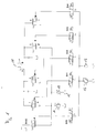
- valve assemblies according to the invention serve to control a hydraulic load 11.
- this is a hydraulic cylinder.
- a hydraulic motor could also be activated.
- the hydraulic consumer 11 has two connections, which form the inlet or outlet depending on the direction of movement. Furthermore, a hydraulic pump 10 is provided, which provides hydraulic pressure for operating the hydraulic consumer 11, as well as a tank 12, to which hydraulic fluid can flow back.
- the valve arrangement according to the invention now has two consumer ports A and B for connection to the terminals of the hydraulic consumer 11, a pressure port P for connection to the hydraulic pump 12 and a tank port T for connection to a return line leading to the tank.
- the individual connections can also be designed in the form of a plurality of connections connected in parallel.
- valve assembly is a valve assembly with dissolved control edges, so that the two consumer terminals A and B and both directions of movement of the consumer via separate valves and thus not mechanically interconnected control edges are controlled.
- valves 1 to 4 are present in the embodiment, wherein valve 1, the pressure port P to the first consumer port A, valve 2, the tank port T with the first consumer port A, valve 3, the pressure port P to the second consumer port B and valve 4, the tank port T. connects to the second consumer terminal B.
- 2/2-way valves are used as valves.
- valves for controlling the two load ports could also be an arrangement with only two separate valves are used. In such an arrangement, either the two consumer connections could then be controlled separately, or the two directions of movement of the hydraulic consumer. For example, two 3/3-way valves could be used for this purpose.
- valves for controlling the two consumer connections or directions of movement allows for a separate and possibly different control of the valves, and on the other hand, the use of different sized valves. These two options can be used both individually and combined to adapt to the particular application and thus to reduce losses.
- valve or the valves which connect or connect the first consumer connection A to the pressure connection P and the tank connection T can be designed differently from the valve or the valves connecting the second consumer connection B to the tank connection T and the pressure connection P . connect.
- different valve cross sections can be used.
- the valve or valves which actuate a first direction of movement of the hydraulic consumer be designed differently from the valve or valves which actuate a second direction of movement.
- valve 5 which connects the pressure port P to the tank port T.
- the valve 5 is designed as a separate valve to the other valves. As a result, there is a further separate control edge, via which a direct connection between the pressure connection and the tank connection can be established.
- valve 5 an "open center” function can be realized, which connects pressure port and tank connection with each other when the two consumer ports are disconnected from the pressure port and vice versa.
- a corresponding control is provided for this purpose.
- the controller is designed so that the valve 5 closes when one of the valves for connecting the pressure port opens with one of the two load ports, so as to throttle the flow.
- valves 1 to 5 are hydraulically controlled.
- a hydraulic pump 13 is provided in each case, which provides the control pressure required for this purpose.
- a separate control valve SV1 to SV5 is provided for each of the valves 1 to 5.
- a control valve while 3/3-way valves are used.
- the control valves SV1 to SV5 can be electrically controlled, for example.
- control valves SV1 to SV5 can also be integrated in the valves 1 to 5, so that in each case two-stage valves are used.
- control valve SV1 'and SV2' are used to control the valves 1 to 5.
- the control valve SV1 ' controls the valves 1 and 4, that is, the connection of the first consumer port A to the pressure port and the connection of the second consumer port B to the tank port.
- the second control valve SV2 ' controls, however, the valves 2 and 3, that is, the connection of the second consumer port to the pressure port and the connection of the first consumer port to the tank port.
- the first control valve SV1 'thus controls the first direction of movement, in which the terminal A of the consumer is pressurized, while hydraulic fluid from the second terminal B flows.
- the control valve SV2 ' controls the opposite direction.
- the control valves SV1 'and SV2' for controlling the valves 1 to 4 are now also used to control the valve 5 to connect the pressure port and tank port.
- the control terminal of the valve 5 via check valves 16 with the control lines for controlling the valves 1 to 4 in connection.
- the check valves 16 ensure that the respective highest control pressure is applied to the control terminal of the valve 5. The valve 5 is thereby automatically closed when one of the valves 1 to 4 is opened.
- a corresponding control of the valve 5 for the connection of pressure connection and tank connection would also be in the in FIG. 1 embodiment shown conceivable by dispensing with the control valve SV5 and the control terminal of the valve 5 is connected via check valves to the control lines for the valves 1 to 4.
Landscapes
- Engineering & Computer Science (AREA)
- Physics & Mathematics (AREA)
- Fluid Mechanics (AREA)
- Mechanical Engineering (AREA)
- General Engineering & Computer Science (AREA)
- Fluid-Pressure Circuits (AREA)
- Valve Housings (AREA)
Applications Claiming Priority (2)
| Application Number | Priority Date | Filing Date | Title |
|---|---|---|---|
| DE102011106081 | 2011-06-30 | ||
| CH01393/11A CH705150A1 (de) | 2011-06-30 | 2011-08-25 | Ventilanordnung für ein hydraulisches Steuerungssystem. |
Publications (3)
| Publication Number | Publication Date |
|---|---|
| EP2541071A2 true EP2541071A2 (fr) | 2013-01-02 |
| EP2541071A3 EP2541071A3 (fr) | 2016-12-07 |
| EP2541071B1 EP2541071B1 (fr) | 2020-11-11 |
Family
ID=46245447
Family Applications (1)
| Application Number | Title | Priority Date | Filing Date |
|---|---|---|---|
| EP12004137.1A Not-in-force EP2541071B1 (fr) | 2011-06-30 | 2012-05-29 | Agencement de soupapes pour un système de commande hydraulique |
Country Status (1)
| Country | Link |
|---|---|
| EP (1) | EP2541071B1 (fr) |
Cited By (2)
| Publication number | Priority date | Publication date | Assignee | Title |
|---|---|---|---|---|
| CN105987036A (zh) * | 2015-02-05 | 2016-10-05 | 徐工集团工程机械股份有限公司 | 支腿控制组合阀、液压系统及起重机 |
| US20230142326A1 (en) * | 2021-11-08 | 2023-05-11 | Pdc Machines, Inc. | High-throughput diaphragm compressor |
Family Cites Families (4)
| Publication number | Priority date | Publication date | Assignee | Title |
|---|---|---|---|---|
| US3411536A (en) * | 1966-07-06 | 1968-11-19 | Koehring Co | Pilot operated control valve mechanism |
| US4723576A (en) * | 1985-06-24 | 1988-02-09 | Fluidcircuit Technologies, Inc. | Fluid power control system |
| DE19500749C2 (de) * | 1995-01-12 | 2000-12-07 | Danfoss As | Drei- oder Mehr-Wege-Ventil |
| US6467264B1 (en) * | 2001-05-02 | 2002-10-22 | Husco International, Inc. | Hydraulic circuit with a return line metering valve and method of operation |
-
2012
- 2012-05-29 EP EP12004137.1A patent/EP2541071B1/fr not_active Not-in-force
Non-Patent Citations (1)
| Title |
|---|
| None |
Cited By (2)
| Publication number | Priority date | Publication date | Assignee | Title |
|---|---|---|---|---|
| CN105987036A (zh) * | 2015-02-05 | 2016-10-05 | 徐工集团工程机械股份有限公司 | 支腿控制组合阀、液压系统及起重机 |
| US20230142326A1 (en) * | 2021-11-08 | 2023-05-11 | Pdc Machines, Inc. | High-throughput diaphragm compressor |
Also Published As
| Publication number | Publication date |
|---|---|
| EP2541071A3 (fr) | 2016-12-07 |
| EP2541071B1 (fr) | 2020-11-11 |
Similar Documents
| Publication | Publication Date | Title |
|---|---|---|
| EP1767824B1 (fr) | Système de commande hydraulique pour une boîte de vitesses à double embrayage automatisée | |
| EP3058236B1 (fr) | Dispositif de commande | |
| DE102010034187A1 (de) | Steuereinrichtung für erstes und zweites Arbeitsgerät | |
| DE102018003728A1 (de) | Ventilanordnung zur Druckmittelversorgung eines hydraulischen Verbrauchers | |
| EP3012463A1 (fr) | Agregat hydraulique | |
| EP3625457B1 (fr) | Dispositif de contrôle de l'approvisionnement d'au moins un consommateur hydraulique avec fluide | |
| EP2672124A2 (fr) | Système hydraulique et vanne de limitation de pression | |
| DE102010043372A1 (de) | Fahrzeuglenksystem | |
| DE102016205582A1 (de) | Hydraulische Antriebsvorrichtung mit Regenerationsbetrieb | |
| EP2157320B1 (fr) | Commande hydraulique pour un moteur hydraulique | |
| EP2541071B1 (fr) | Agencement de soupapes pour un système de commande hydraulique | |
| EP3436705B1 (fr) | Dispositif de commande | |
| DE102016123503B4 (de) | Hydraulikventilverband | |
| DE102015212101A1 (de) | Hydrauliksteuerung für einen Aktuator in einem Fahrzeuggetriebe | |
| DE102013002814A1 (de) | Hydrauliksystem für eine Arbeitsvorrichtung | |
| EP1574720B1 (fr) | Commande électro-hydraulique et méthode de sa déactivation | |
| DE102017002784A1 (de) | Steuereinheit für eine Steuerungsvorrichtung für ein Schwerlast-Fahrzeug, insbesondere für einen Schwanenhals, eine Hubanordnung oder eine Lenkanordnung eines Schwerlast-Fahrzeugs, sowie eine derartige Steuerungsvorrichtung | |
| DE102016212306A1 (de) | Zwischenblock und Kompaktachse mit einem Zwischenblock | |
| CH705150A1 (de) | Ventilanordnung für ein hydraulisches Steuerungssystem. | |
| EP1161929A2 (fr) | Système hydraulique pour une table, en particulier table d'opération, comprenant plusieurs consommateurs hydrauliques | |
| DE102007057624A1 (de) | Vorrichtung und Verfahren zum Betätigen eines elektrischen Systems, insbesondere eines Cabriolet-Verdecks | |
| DE102017102307B3 (de) | Kraftfahrzeug mit offener Fahrgastzelle | |
| EP1215397B1 (fr) | Bloc de distributeur à voies multiples | |
| DE3640640C2 (de) | Hydrostatisches Antriebssystem mit einem Verbraucher mit zwei Anschlüssen | |
| DE102009058404A1 (de) | Schaltungsanordnung zur Ansteuerung eines doppelt wirkenden Verbrauchers |
Legal Events
| Date | Code | Title | Description |
|---|---|---|---|
| PUAI | Public reference made under article 153(3) epc to a published international application that has entered the european phase |
Free format text: ORIGINAL CODE: 0009012 |
|
| AK | Designated contracting states |
Kind code of ref document: A2 Designated state(s): AL AT BE BG CH CY CZ DE DK EE ES FI FR GB GR HR HU IE IS IT LI LT LU LV MC MK MT NL NO PL PT RO RS SE SI SK SM TR |
|
| AX | Request for extension of the european patent |
Extension state: BA ME |
|
| PUAL | Search report despatched |
Free format text: ORIGINAL CODE: 0009013 |
|
| AK | Designated contracting states |
Kind code of ref document: A3 Designated state(s): AL AT BE BG CH CY CZ DE DK EE ES FI FR GB GR HR HU IE IS IT LI LT LU LV MC MK MT NL NO PL PT RO RS SE SI SK SM TR |
|
| AX | Request for extension of the european patent |
Extension state: BA ME |
|
| RIC1 | Information provided on ipc code assigned before grant |
Ipc: F15B 11/00 20060101AFI20161102BHEP |
|
| STAA | Information on the status of an ep patent application or granted ep patent |
Free format text: STATUS: REQUEST FOR EXAMINATION WAS MADE |
|
| 17P | Request for examination filed |
Effective date: 20170607 |
|
| STAA | Information on the status of an ep patent application or granted ep patent |
Free format text: STATUS: EXAMINATION IS IN PROGRESS |
|
| 17Q | First examination report despatched |
Effective date: 20181115 |
|
| GRAP | Despatch of communication of intention to grant a patent |
Free format text: ORIGINAL CODE: EPIDOSNIGR1 |
|
| STAA | Information on the status of an ep patent application or granted ep patent |
Free format text: STATUS: GRANT OF PATENT IS INTENDED |
|
| INTG | Intention to grant announced |
Effective date: 20200515 |
|
| GRAS | Grant fee paid |
Free format text: ORIGINAL CODE: EPIDOSNIGR3 |
|
| GRAA | (expected) grant |
Free format text: ORIGINAL CODE: 0009210 |
|
| STAA | Information on the status of an ep patent application or granted ep patent |
Free format text: STATUS: THE PATENT HAS BEEN GRANTED |
|
| RAP1 | Party data changed (applicant data changed or rights of an application transferred) |
Owner name: LIEBHERR-MACHINES BULLE SA |
|
| AK | Designated contracting states |
Kind code of ref document: B1 Designated state(s): AL AT BE BG CH CY CZ DE DK EE ES FI FR GB GR HR HU IE IS IT LI LT LU LV MC MK MT NL NO PL PT RO RS SE SI SK SM TR |
|
| RAP1 | Party data changed (applicant data changed or rights of an application transferred) |
Owner name: LIEBHERR MACHINES BULLE SA |
|
| REG | Reference to a national code |
Ref country code: GB Ref legal event code: FG4D Free format text: NOT ENGLISH |
|
| REG | Reference to a national code |
Ref country code: CH Ref legal event code: EP |
|
| REG | Reference to a national code |
Ref country code: AT Ref legal event code: REF Ref document number: 1333745 Country of ref document: AT Kind code of ref document: T Effective date: 20201115 |
|
| REG | Reference to a national code |
Ref country code: DE Ref legal event code: R096 Ref document number: 502012016466 Country of ref document: DE |
|
| REG | Reference to a national code |
Ref country code: IE Ref legal event code: FG4D Free format text: LANGUAGE OF EP DOCUMENT: GERMAN |
|
| REG | Reference to a national code |
Ref country code: NL Ref legal event code: MP Effective date: 20201111 |
|
| PG25 | Lapsed in a contracting state [announced via postgrant information from national office to epo] |
Ref country code: GR Free format text: LAPSE BECAUSE OF FAILURE TO SUBMIT A TRANSLATION OF THE DESCRIPTION OR TO PAY THE FEE WITHIN THE PRESCRIBED TIME-LIMIT Effective date: 20210212 Ref country code: RS Free format text: LAPSE BECAUSE OF FAILURE TO SUBMIT A TRANSLATION OF THE DESCRIPTION OR TO PAY THE FEE WITHIN THE PRESCRIBED TIME-LIMIT Effective date: 20201111 Ref country code: FI Free format text: LAPSE BECAUSE OF FAILURE TO SUBMIT A TRANSLATION OF THE DESCRIPTION OR TO PAY THE FEE WITHIN THE PRESCRIBED TIME-LIMIT Effective date: 20201111 Ref country code: PT Free format text: LAPSE BECAUSE OF FAILURE TO SUBMIT A TRANSLATION OF THE DESCRIPTION OR TO PAY THE FEE WITHIN THE PRESCRIBED TIME-LIMIT Effective date: 20210311 Ref country code: NO Free format text: LAPSE BECAUSE OF FAILURE TO SUBMIT A TRANSLATION OF THE DESCRIPTION OR TO PAY THE FEE WITHIN THE PRESCRIBED TIME-LIMIT Effective date: 20210211 |
|
| PG25 | Lapsed in a contracting state [announced via postgrant information from national office to epo] |
Ref country code: LV Free format text: LAPSE BECAUSE OF FAILURE TO SUBMIT A TRANSLATION OF THE DESCRIPTION OR TO PAY THE FEE WITHIN THE PRESCRIBED TIME-LIMIT Effective date: 20201111 Ref country code: PL Free format text: LAPSE BECAUSE OF FAILURE TO SUBMIT A TRANSLATION OF THE DESCRIPTION OR TO PAY THE FEE WITHIN THE PRESCRIBED TIME-LIMIT Effective date: 20201111 Ref country code: SE Free format text: LAPSE BECAUSE OF FAILURE TO SUBMIT A TRANSLATION OF THE DESCRIPTION OR TO PAY THE FEE WITHIN THE PRESCRIBED TIME-LIMIT Effective date: 20201111 Ref country code: IS Free format text: LAPSE BECAUSE OF FAILURE TO SUBMIT A TRANSLATION OF THE DESCRIPTION OR TO PAY THE FEE WITHIN THE PRESCRIBED TIME-LIMIT Effective date: 20210311 Ref country code: BG Free format text: LAPSE BECAUSE OF FAILURE TO SUBMIT A TRANSLATION OF THE DESCRIPTION OR TO PAY THE FEE WITHIN THE PRESCRIBED TIME-LIMIT Effective date: 20210211 |
|
| REG | Reference to a national code |
Ref country code: LT Ref legal event code: MG9D |
|
| PG25 | Lapsed in a contracting state [announced via postgrant information from national office to epo] |
Ref country code: HR Free format text: LAPSE BECAUSE OF FAILURE TO SUBMIT A TRANSLATION OF THE DESCRIPTION OR TO PAY THE FEE WITHIN THE PRESCRIBED TIME-LIMIT Effective date: 20201111 |
|
| PG25 | Lapsed in a contracting state [announced via postgrant information from national office to epo] |
Ref country code: RO Free format text: LAPSE BECAUSE OF FAILURE TO SUBMIT A TRANSLATION OF THE DESCRIPTION OR TO PAY THE FEE WITHIN THE PRESCRIBED TIME-LIMIT Effective date: 20201111 Ref country code: SK Free format text: LAPSE BECAUSE OF FAILURE TO SUBMIT A TRANSLATION OF THE DESCRIPTION OR TO PAY THE FEE WITHIN THE PRESCRIBED TIME-LIMIT Effective date: 20201111 Ref country code: LT Free format text: LAPSE BECAUSE OF FAILURE TO SUBMIT A TRANSLATION OF THE DESCRIPTION OR TO PAY THE FEE WITHIN THE PRESCRIBED TIME-LIMIT Effective date: 20201111 Ref country code: SM Free format text: LAPSE BECAUSE OF FAILURE TO SUBMIT A TRANSLATION OF THE DESCRIPTION OR TO PAY THE FEE WITHIN THE PRESCRIBED TIME-LIMIT Effective date: 20201111 Ref country code: EE Free format text: LAPSE BECAUSE OF FAILURE TO SUBMIT A TRANSLATION OF THE DESCRIPTION OR TO PAY THE FEE WITHIN THE PRESCRIBED TIME-LIMIT Effective date: 20201111 Ref country code: CZ Free format text: LAPSE BECAUSE OF FAILURE TO SUBMIT A TRANSLATION OF THE DESCRIPTION OR TO PAY THE FEE WITHIN THE PRESCRIBED TIME-LIMIT Effective date: 20201111 |
|
| REG | Reference to a national code |
Ref country code: DE Ref legal event code: R097 Ref document number: 502012016466 Country of ref document: DE |
|
| PG25 | Lapsed in a contracting state [announced via postgrant information from national office to epo] |
Ref country code: DK Free format text: LAPSE BECAUSE OF FAILURE TO SUBMIT A TRANSLATION OF THE DESCRIPTION OR TO PAY THE FEE WITHIN THE PRESCRIBED TIME-LIMIT Effective date: 20201111 |
|
| PLBE | No opposition filed within time limit |
Free format text: ORIGINAL CODE: 0009261 |
|
| STAA | Information on the status of an ep patent application or granted ep patent |
Free format text: STATUS: NO OPPOSITION FILED WITHIN TIME LIMIT |
|
| 26N | No opposition filed |
Effective date: 20210812 |
|
| PG25 | Lapsed in a contracting state [announced via postgrant information from national office to epo] |
Ref country code: NL Free format text: LAPSE BECAUSE OF FAILURE TO SUBMIT A TRANSLATION OF THE DESCRIPTION OR TO PAY THE FEE WITHIN THE PRESCRIBED TIME-LIMIT Effective date: 20201111 Ref country code: IT Free format text: LAPSE BECAUSE OF FAILURE TO SUBMIT A TRANSLATION OF THE DESCRIPTION OR TO PAY THE FEE WITHIN THE PRESCRIBED TIME-LIMIT Effective date: 20201111 Ref country code: AL Free format text: LAPSE BECAUSE OF FAILURE TO SUBMIT A TRANSLATION OF THE DESCRIPTION OR TO PAY THE FEE WITHIN THE PRESCRIBED TIME-LIMIT Effective date: 20201111 |
|
| PG25 | Lapsed in a contracting state [announced via postgrant information from national office to epo] |
Ref country code: SI Free format text: LAPSE BECAUSE OF FAILURE TO SUBMIT A TRANSLATION OF THE DESCRIPTION OR TO PAY THE FEE WITHIN THE PRESCRIBED TIME-LIMIT Effective date: 20201111 Ref country code: ES Free format text: LAPSE BECAUSE OF FAILURE TO SUBMIT A TRANSLATION OF THE DESCRIPTION OR TO PAY THE FEE WITHIN THE PRESCRIBED TIME-LIMIT Effective date: 20201111 |
|
| REG | Reference to a national code |
Ref country code: CH Ref legal event code: PL |
|
| GBPC | Gb: european patent ceased through non-payment of renewal fee |
Effective date: 20210529 |
|
| PG25 | Lapsed in a contracting state [announced via postgrant information from national office to epo] |
Ref country code: LI Free format text: LAPSE BECAUSE OF NON-PAYMENT OF DUE FEES Effective date: 20210531 Ref country code: MC Free format text: LAPSE BECAUSE OF FAILURE TO SUBMIT A TRANSLATION OF THE DESCRIPTION OR TO PAY THE FEE WITHIN THE PRESCRIBED TIME-LIMIT Effective date: 20201111 Ref country code: LU Free format text: LAPSE BECAUSE OF NON-PAYMENT OF DUE FEES Effective date: 20210529 Ref country code: CH Free format text: LAPSE BECAUSE OF NON-PAYMENT OF DUE FEES Effective date: 20210531 |
|
| REG | Reference to a national code |
Ref country code: BE Ref legal event code: MM Effective date: 20210531 |
|
| PG25 | Lapsed in a contracting state [announced via postgrant information from national office to epo] |
Ref country code: IE Free format text: LAPSE BECAUSE OF NON-PAYMENT OF DUE FEES Effective date: 20210529 Ref country code: GB Free format text: LAPSE BECAUSE OF NON-PAYMENT OF DUE FEES Effective date: 20210529 |
|
| PG25 | Lapsed in a contracting state [announced via postgrant information from national office to epo] |
Ref country code: IS Free format text: LAPSE BECAUSE OF FAILURE TO SUBMIT A TRANSLATION OF THE DESCRIPTION OR TO PAY THE FEE WITHIN THE PRESCRIBED TIME-LIMIT Effective date: 20210311 Ref country code: FR Free format text: LAPSE BECAUSE OF NON-PAYMENT OF DUE FEES Effective date: 20210531 |
|
| REG | Reference to a national code |
Ref country code: AT Ref legal event code: MM01 Ref document number: 1333745 Country of ref document: AT Kind code of ref document: T Effective date: 20210529 |
|
| PG25 | Lapsed in a contracting state [announced via postgrant information from national office to epo] |
Ref country code: BE Free format text: LAPSE BECAUSE OF NON-PAYMENT OF DUE FEES Effective date: 20210531 |
|
| PG25 | Lapsed in a contracting state [announced via postgrant information from national office to epo] |
Ref country code: AT Free format text: LAPSE BECAUSE OF NON-PAYMENT OF DUE FEES Effective date: 20210529 |
|
| PG25 | Lapsed in a contracting state [announced via postgrant information from national office to epo] |
Ref country code: HU Free format text: LAPSE BECAUSE OF FAILURE TO SUBMIT A TRANSLATION OF THE DESCRIPTION OR TO PAY THE FEE WITHIN THE PRESCRIBED TIME-LIMIT; INVALID AB INITIO Effective date: 20120529 Ref country code: CY Free format text: LAPSE BECAUSE OF FAILURE TO SUBMIT A TRANSLATION OF THE DESCRIPTION OR TO PAY THE FEE WITHIN THE PRESCRIBED TIME-LIMIT Effective date: 20201111 |
|
| PG25 | Lapsed in a contracting state [announced via postgrant information from national office to epo] |
Ref country code: MK Free format text: LAPSE BECAUSE OF FAILURE TO SUBMIT A TRANSLATION OF THE DESCRIPTION OR TO PAY THE FEE WITHIN THE PRESCRIBED TIME-LIMIT Effective date: 20201111 |
|
| PGFP | Annual fee paid to national office [announced via postgrant information from national office to epo] |
Ref country code: DE Payment date: 20240523 Year of fee payment: 13 |
|
| PG25 | Lapsed in a contracting state [announced via postgrant information from national office to epo] |
Ref country code: MT Free format text: LAPSE BECAUSE OF FAILURE TO SUBMIT A TRANSLATION OF THE DESCRIPTION OR TO PAY THE FEE WITHIN THE PRESCRIBED TIME-LIMIT Effective date: 20201111 |
|
| REG | Reference to a national code |
Ref country code: DE Ref legal event code: R119 Ref document number: 502012016466 Country of ref document: DE |
|
| PG25 | Lapsed in a contracting state [announced via postgrant information from national office to epo] |
Ref country code: TR Free format text: LAPSE BECAUSE OF FAILURE TO SUBMIT A TRANSLATION OF THE DESCRIPTION OR TO PAY THE FEE WITHIN THE PRESCRIBED TIME-LIMIT Effective date: 20201111 |
|
| PG25 | Lapsed in a contracting state [announced via postgrant information from national office to epo] |
Ref country code: DE Free format text: LAPSE BECAUSE OF NON-PAYMENT OF DUE FEES Effective date: 20251202 |