EP2541229A2 - Procédé et système d'élimination de contaminants d'un capteur de matière particulaire - Google Patents
Procédé et système d'élimination de contaminants d'un capteur de matière particulaire Download PDFInfo
- Publication number
- EP2541229A2 EP2541229A2 EP12173092A EP12173092A EP2541229A2 EP 2541229 A2 EP2541229 A2 EP 2541229A2 EP 12173092 A EP12173092 A EP 12173092A EP 12173092 A EP12173092 A EP 12173092A EP 2541229 A2 EP2541229 A2 EP 2541229A2
- Authority
- EP
- European Patent Office
- Prior art keywords
- sensor
- temperature
- particulate matter
- heater
- heating
- Prior art date
- Legal status (The legal status is an assumption and is not a legal conclusion. Google has not performed a legal analysis and makes no representation as to the accuracy of the status listed.)
- Withdrawn
Links
- 239000013618 particulate matter Substances 0.000 title claims abstract description 54
- 238000000034 method Methods 0.000 title claims abstract description 33
- 238000011109 contamination Methods 0.000 title claims abstract description 25
- 239000000758 substrate Substances 0.000 claims abstract description 36
- 238000010438 heat treatment Methods 0.000 claims abstract description 26
- 239000004071 soot Substances 0.000 claims description 25
- 238000004891 communication Methods 0.000 claims description 8
- 238000003860 storage Methods 0.000 claims description 6
- 238000001514 detection method Methods 0.000 claims description 5
- 230000000694 effects Effects 0.000 claims description 5
- 230000001351 cycling effect Effects 0.000 claims description 2
- 239000000356 contaminant Substances 0.000 abstract description 26
- 239000000463 material Substances 0.000 description 21
- BASFCYQUMIYNBI-UHFFFAOYSA-N platinum Chemical compound [Pt] BASFCYQUMIYNBI-UHFFFAOYSA-N 0.000 description 18
- 238000011069 regeneration method Methods 0.000 description 17
- 230000008929 regeneration Effects 0.000 description 15
- 239000004020 conductor Substances 0.000 description 14
- 229910052697 platinum Inorganic materials 0.000 description 9
- 238000005259 measurement Methods 0.000 description 8
- KDLHZDBZIXYQEI-UHFFFAOYSA-N Palladium Chemical compound [Pd] KDLHZDBZIXYQEI-UHFFFAOYSA-N 0.000 description 6
- 239000007789 gas Substances 0.000 description 5
- 239000012535 impurity Substances 0.000 description 5
- 230000000670 limiting effect Effects 0.000 description 5
- UQSXHKLRYXJYBZ-UHFFFAOYSA-N Iron oxide Chemical compound [Fe]=O UQSXHKLRYXJYBZ-UHFFFAOYSA-N 0.000 description 4
- 238000002485 combustion reaction Methods 0.000 description 4
- 230000007423 decrease Effects 0.000 description 4
- 238000005516 engineering process Methods 0.000 description 4
- 239000000446 fuel Substances 0.000 description 4
- 239000010410 layer Substances 0.000 description 4
- 230000008569 process Effects 0.000 description 4
- 239000011241 protective layer Substances 0.000 description 4
- 230000004044 response Effects 0.000 description 4
- PNEYBMLMFCGWSK-UHFFFAOYSA-N aluminium oxide Inorganic materials [O-2].[O-2].[O-2].[Al+3].[Al+3] PNEYBMLMFCGWSK-UHFFFAOYSA-N 0.000 description 3
- 125000004122 cyclic group Chemical group 0.000 description 3
- PCHJSUWPFVWCPO-UHFFFAOYSA-N gold Chemical compound [Au] PCHJSUWPFVWCPO-UHFFFAOYSA-N 0.000 description 3
- 229910052737 gold Inorganic materials 0.000 description 3
- 239000010931 gold Substances 0.000 description 3
- 150000002430 hydrocarbons Chemical class 0.000 description 3
- 229910052751 metal Inorganic materials 0.000 description 3
- 239000002184 metal Substances 0.000 description 3
- 229910052763 palladium Inorganic materials 0.000 description 3
- 238000012545 processing Methods 0.000 description 3
- 238000000926 separation method Methods 0.000 description 3
- KJTLSVCANCCWHF-UHFFFAOYSA-N Ruthenium Chemical compound [Ru] KJTLSVCANCCWHF-UHFFFAOYSA-N 0.000 description 2
- VYPSYNLAJGMNEJ-UHFFFAOYSA-N Silicium dioxide Chemical compound O=[Si]=O VYPSYNLAJGMNEJ-UHFFFAOYSA-N 0.000 description 2
- RTAQQCXQSZGOHL-UHFFFAOYSA-N Titanium Chemical compound [Ti] RTAQQCXQSZGOHL-UHFFFAOYSA-N 0.000 description 2
- QCWXUUIWCKQGHC-UHFFFAOYSA-N Zirconium Chemical compound [Zr] QCWXUUIWCKQGHC-UHFFFAOYSA-N 0.000 description 2
- MCMNRKCIXSYSNV-UHFFFAOYSA-N Zirconium dioxide Chemical compound O=[Zr]=O MCMNRKCIXSYSNV-UHFFFAOYSA-N 0.000 description 2
- 239000000956 alloy Substances 0.000 description 2
- 229910045601 alloy Inorganic materials 0.000 description 2
- 229910052782 aluminium Inorganic materials 0.000 description 2
- XAGFODPZIPBFFR-UHFFFAOYSA-N aluminium Chemical compound [Al] XAGFODPZIPBFFR-UHFFFAOYSA-N 0.000 description 2
- 230000015572 biosynthetic process Effects 0.000 description 2
- 239000011195 cermet Substances 0.000 description 2
- 230000008859 change Effects 0.000 description 2
- 238000005229 chemical vapour deposition Methods 0.000 description 2
- 238000000151 deposition Methods 0.000 description 2
- 230000008021 deposition Effects 0.000 description 2
- 239000012777 electrically insulating material Substances 0.000 description 2
- 238000010285 flame spraying Methods 0.000 description 2
- 239000000295 fuel oil Substances 0.000 description 2
- 230000006870 function Effects 0.000 description 2
- 229930195733 hydrocarbon Natural products 0.000 description 2
- 230000000977 initiatory effect Effects 0.000 description 2
- 229910052741 iridium Inorganic materials 0.000 description 2
- GKOZUEZYRPOHIO-UHFFFAOYSA-N iridium atom Chemical compound [Ir] GKOZUEZYRPOHIO-UHFFFAOYSA-N 0.000 description 2
- 238000003475 lamination Methods 0.000 description 2
- MRELNEQAGSRDBK-UHFFFAOYSA-N lanthanum(3+);oxygen(2-) Chemical compound [O-2].[O-2].[O-2].[La+3].[La+3] MRELNEQAGSRDBK-UHFFFAOYSA-N 0.000 description 2
- 150000002739 metals Chemical class 0.000 description 2
- 229910052762 osmium Inorganic materials 0.000 description 2
- SYQBFIAQOQZEGI-UHFFFAOYSA-N osmium atom Chemical compound [Os] SYQBFIAQOQZEGI-UHFFFAOYSA-N 0.000 description 2
- 229910052703 rhodium Inorganic materials 0.000 description 2
- 239000010948 rhodium Substances 0.000 description 2
- MHOVAHRLVXNVSD-UHFFFAOYSA-N rhodium atom Chemical compound [Rh] MHOVAHRLVXNVSD-UHFFFAOYSA-N 0.000 description 2
- 229910052707 ruthenium Inorganic materials 0.000 description 2
- 238000007650 screen-printing Methods 0.000 description 2
- 238000004544 sputter deposition Methods 0.000 description 2
- 229910052719 titanium Inorganic materials 0.000 description 2
- 239000010936 titanium Substances 0.000 description 2
- 229910052726 zirconium Inorganic materials 0.000 description 2
- OYPRJOBELJOOCE-UHFFFAOYSA-N Calcium Chemical compound [Ca] OYPRJOBELJOOCE-UHFFFAOYSA-N 0.000 description 1
- 239000004215 Carbon black (E152) Substances 0.000 description 1
- UGFAIRIUMAVXCW-UHFFFAOYSA-N Carbon monoxide Chemical compound [O+]#[C-] UGFAIRIUMAVXCW-UHFFFAOYSA-N 0.000 description 1
- QPLDLSVMHZLSFG-UHFFFAOYSA-N Copper oxide Chemical compound [Cu]=O QPLDLSVMHZLSFG-UHFFFAOYSA-N 0.000 description 1
- 239000005751 Copper oxide Substances 0.000 description 1
- DGAQECJNVWCQMB-PUAWFVPOSA-M Ilexoside XXIX Chemical compound C[C@@H]1CC[C@@]2(CC[C@@]3(C(=CC[C@H]4[C@]3(CC[C@@H]5[C@@]4(CC[C@@H](C5(C)C)OS(=O)(=O)[O-])C)C)[C@@H]2[C@]1(C)O)C)C(=O)O[C@H]6[C@@H]([C@H]([C@@H]([C@H](O6)CO)O)O)O.[Na+] DGAQECJNVWCQMB-PUAWFVPOSA-M 0.000 description 1
- WHXSMMKQMYFTQS-UHFFFAOYSA-N Lithium Chemical compound [Li] WHXSMMKQMYFTQS-UHFFFAOYSA-N 0.000 description 1
- ZLMJMSJWJFRBEC-UHFFFAOYSA-N Potassium Chemical compound [K] ZLMJMSJWJFRBEC-UHFFFAOYSA-N 0.000 description 1
- 239000000654 additive Substances 0.000 description 1
- 230000032683 aging Effects 0.000 description 1
- 238000003915 air pollution Methods 0.000 description 1
- 230000004075 alteration Effects 0.000 description 1
- QVGXLLKOCUKJST-UHFFFAOYSA-N atomic oxygen Chemical compound [O] QVGXLLKOCUKJST-UHFFFAOYSA-N 0.000 description 1
- 230000033228 biological regulation Effects 0.000 description 1
- 239000011575 calcium Substances 0.000 description 1
- 229910052791 calcium Inorganic materials 0.000 description 1
- BRPQOXSCLDDYGP-UHFFFAOYSA-N calcium oxide Chemical compound [O-2].[Ca+2] BRPQOXSCLDDYGP-UHFFFAOYSA-N 0.000 description 1
- 239000000292 calcium oxide Substances 0.000 description 1
- ODINCKMPIJJUCX-UHFFFAOYSA-N calcium oxide Inorganic materials [Ca]=O ODINCKMPIJJUCX-UHFFFAOYSA-N 0.000 description 1
- 229910002091 carbon monoxide Inorganic materials 0.000 description 1
- 239000000919 ceramic Substances 0.000 description 1
- 229910000420 cerium oxide Inorganic materials 0.000 description 1
- 238000002144 chemical decomposition reaction Methods 0.000 description 1
- 238000006243 chemical reaction Methods 0.000 description 1
- 238000004590 computer program Methods 0.000 description 1
- 239000002826 coolant Substances 0.000 description 1
- 229910000431 copper oxide Inorganic materials 0.000 description 1
- 230000003247 decreasing effect Effects 0.000 description 1
- 230000000593 degrading effect Effects 0.000 description 1
- 230000032798 delamination Effects 0.000 description 1
- 230000001419 dependent effect Effects 0.000 description 1
- 238000013461 design Methods 0.000 description 1
- 238000002405 diagnostic procedure Methods 0.000 description 1
- 239000002283 diesel fuel Substances 0.000 description 1
- 239000003344 environmental pollutant Substances 0.000 description 1
- 238000001914 filtration Methods 0.000 description 1
- 238000002847 impedance measurement Methods 0.000 description 1
- 230000002401 inhibitory effect Effects 0.000 description 1
- 238000002955 isolation Methods 0.000 description 1
- 238000010030 laminating Methods 0.000 description 1
- 229910052744 lithium Inorganic materials 0.000 description 1
- 238000002156 mixing Methods 0.000 description 1
- 239000000203 mixture Substances 0.000 description 1
- 239000010705 motor oil Substances 0.000 description 1
- 230000003647 oxidation Effects 0.000 description 1
- 238000007254 oxidation reaction Methods 0.000 description 1
- BMMGVYCKOGBVEV-UHFFFAOYSA-N oxo(oxoceriooxy)cerium Chemical compound [Ce]=O.O=[Ce]=O BMMGVYCKOGBVEV-UHFFFAOYSA-N 0.000 description 1
- 229910052760 oxygen Inorganic materials 0.000 description 1
- 239000001301 oxygen Substances 0.000 description 1
- 239000002245 particle Substances 0.000 description 1
- 230000002085 persistent effect Effects 0.000 description 1
- 231100000719 pollutant Toxicity 0.000 description 1
- 229910052700 potassium Inorganic materials 0.000 description 1
- 239000011591 potassium Substances 0.000 description 1
- 239000000843 powder Substances 0.000 description 1
- 238000007639 printing Methods 0.000 description 1
- 230000009467 reduction Effects 0.000 description 1
- 230000002829 reductive effect Effects 0.000 description 1
- 239000000523 sample Substances 0.000 description 1
- 238000005070 sampling Methods 0.000 description 1
- 230000035945 sensitivity Effects 0.000 description 1
- 239000000377 silicon dioxide Substances 0.000 description 1
- 239000002356 single layer Substances 0.000 description 1
- 230000000391 smoking effect Effects 0.000 description 1
- 229910052708 sodium Inorganic materials 0.000 description 1
- 239000011734 sodium Substances 0.000 description 1
- 239000002904 solvent Substances 0.000 description 1
- 239000000126 substance Substances 0.000 description 1
- 238000006467 substitution reaction Methods 0.000 description 1
- -1 such as Substances 0.000 description 1
- 238000010345 tape casting Methods 0.000 description 1
- 238000005979 thermal decomposition reaction Methods 0.000 description 1
- 230000008646 thermal stress Effects 0.000 description 1
- 238000012546 transfer Methods 0.000 description 1
- XLYOFNOQVPJJNP-UHFFFAOYSA-N water Substances O XLYOFNOQVPJJNP-UHFFFAOYSA-N 0.000 description 1
- RUDFQVOCFDJEEF-UHFFFAOYSA-N yttrium(III) oxide Inorganic materials [O-2].[O-2].[O-2].[Y+3].[Y+3] RUDFQVOCFDJEEF-UHFFFAOYSA-N 0.000 description 1
Images

Classifications
-
- G—PHYSICS
- G01—MEASURING; TESTING
- G01N—INVESTIGATING OR ANALYSING MATERIALS BY DETERMINING THEIR CHEMICAL OR PHYSICAL PROPERTIES
- G01N15/00—Investigating characteristics of particles; Investigating permeability, pore-volume or surface-area of porous materials
- G01N15/06—Investigating concentration of particle suspensions
- G01N15/0656—Investigating concentration of particle suspensions using electric, e.g. electrostatic methods or magnetic methods
-
- F—MECHANICAL ENGINEERING; LIGHTING; HEATING; WEAPONS; BLASTING
- F02—COMBUSTION ENGINES; HOT-GAS OR COMBUSTION-PRODUCT ENGINE PLANTS
- F02D—CONTROLLING COMBUSTION ENGINES
- F02D41/00—Electrical control of supply of combustible mixture or its constituents
- F02D41/02—Circuit arrangements for generating control signals
- F02D41/14—Introducing closed-loop corrections
- F02D41/1438—Introducing closed-loop corrections using means for determining characteristics of the combustion gases; Sensors therefor
- F02D41/1444—Introducing closed-loop corrections using means for determining characteristics of the combustion gases; Sensors therefor characterised by the characteristics of the combustion gases
- F02D41/1466—Introducing closed-loop corrections using means for determining characteristics of the combustion gases; Sensors therefor characterised by the characteristics of the combustion gases the characteristics being a soot concentration or content
-
- F—MECHANICAL ENGINEERING; LIGHTING; HEATING; WEAPONS; BLASTING
- F02—COMBUSTION ENGINES; HOT-GAS OR COMBUSTION-PRODUCT ENGINE PLANTS
- F02D—CONTROLLING COMBUSTION ENGINES
- F02D41/00—Electrical control of supply of combustible mixture or its constituents
- F02D41/02—Circuit arrangements for generating control signals
- F02D41/14—Introducing closed-loop corrections
- F02D41/1438—Introducing closed-loop corrections using means for determining characteristics of the combustion gases; Sensors therefor
- F02D41/1493—Details
- F02D41/1494—Control of sensor heater
Definitions
- This invention relates generally to sensors for detecting electrically conductive particulate matter, such as soot, and more particularly to a method and system for removing contamination from such sensors.
- Particulate sensors such as those described above generally have a pair of spaced apart sensing electrodes disposed on a substrate.
- the sensing electrodes are coupled to a measurement circuit by way of electrically conductive leads.
- the operating principle of the particulate sensor is based on the conductivity of the particulates (e.g., soot) deposited on (or over) the sensing electrodes.
- the electrical resistance between the sensing electrodes is relatively high when the sensor is clean but such resistance decreases as soot particulates accumulate.
- These sensors also have a heater that can be selectively activated to regenerate the sensor, that is, to burn off the soot particulates to "reset" the sensor to a known, base "clean” state.
- a sensor may become “poisoned” by deposition of contamination on the sensor.
- contamination and “contaminant” refer to materials that, when deposited on the sensor, interfere with the ability of the sensor to detect soot deposited on the sensor.
- contaminant materials include iron oxide and calcium oxide. These materials may be introduced, for example, by thermal or chemical decomposition of additives in fuel or motor oil. These contaminant materials may have an electrical resistance that is relatively high at lower temperatures, with the resistance decreasing at increasing temperatures. Deposition of a relative high resistance contaminant layer on the sensor may act to insulate the sensing electrodes from the soot particulates, reducing the sensitivity of the sensor for its intended purpose of sensing particulate matter.
- the contaminant material may be thermally stable at the temperature used to regenerate the sensor, resulting in the contaminant persisting on the surface of the sensor throughout the normal operating conditions of the sensor.
- the present invention relates to a method of removing contamination from a particulate matter sensor.
- the method according to the invention comprises the steps of:
- Exemplary embodiments of the invention also relate to a storage medium encoded with machine readable computer program code for removing contamination from an electrically conductive particulate matter sensor as described above where the storage medium includes instructions for causing a computer to implement the above-described method.
- Another exemplary embodiment of the invention relates to a contamination removal system for an electrically conductive particulate matter sensor as described above, the system comprising a microprocessor in communication with the sensor and a storage medium including instructions for causing the microprocessor to implement the above-described method.
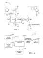
- FIG. 1 is an electrical schematic of a particulate matter sensing system for which the sensor contamination removal of the invention may be practiced.
- FIG. 2 is an electrical schematic of an alternative particulate matter sensing system incorporating a bias resistor for which the sensor contamination removal of the invention may be practiced.
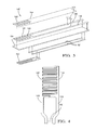
- FIG. 3 is an exploded perspective view of a sensing element as found in the particulate matter sensing system of Fig. 2 .
- FIG. 4 is a plan view of a sensing element as found in the particulate matter sensing system of Fig. 2 .
- FIG. 5 is an electrical schematic that includes aspects of the present invention.
- FIG. 6 is a schematic illustration of an engine control module and a particulate matter sensor.
- measurements of resistance between the electrodes may be made by applying a known current across the electrodes, measuring the voltage differential between the electrodes and calculating the resistance using Ohm's law, as is well-known in the art. It would of course be possible to simply use the voltage values in place of resistance values in the algorithm of the invention by converting the various resistance constants and equations to voltage, and such alternative embodiments are considered to be within the scope of the invention.
- the sensor may include a multi-layered structure comprising the sensing element, the temperature sensor, the heater, and a combination comprising at least one of the foregoing, contained in a single structure formed, e.g., by multi-layer technology.
- the sensing electrodes can include metals, such as, gold, platinum, osmium, rhodium, iridium, ruthenium, aluminum, titanium, zirconium, and the like, as well as, oxides, cermets, alloys, and combinations comprising at least one of the foregoing metals.
- the sensing electrode can comprise a platinum/alumina cermet wherein the platinum is about 90 wt % (weight percent) to about 98 wt % of the sensing electrode.
- the sensing electrode comprises about 93 wt % to about 95 wt % platinum, where weight percent is based on the total dry weight of the cermet.
- Each sensing electrode may be composed of the same or different material as the other sensing electrode(s).
- the sensing electrodes can be formulated in any fashion. In one exemplary embodiment, however, the sensing electrodes are formed by first preparing an ink paste by mixing an electrode forming-metal powder (e.g., platinum, gold, osmium, rhodium, iridium, ruthenium, aluminum, titanium, zirconium, and the like, or combinations of at least one of the foregoing) with oxides in a sufficient amount of solvent to attain a viscosity suitable for printing.
- the oxides used to form the sensing electrodes may include those oxides that do not promote the oxidation of particulates and that do not lower the burn-off temperature of the particulates.
- Non-suitable oxides are, e.g., copper oxide, cerium oxide, and iron oxide.
- the ink paste forming the sensing electrode can then be applied to an electrode substrate via sputtering, chemical vapor deposition, screen printing, flame spraying, lamination, stenciling, or the like.
- the sensing electrodes may be disposed onto the electrode substrate such that a constant distance of separation between each sensing electrode is created.
- a contiguous conductor area may be disposed on the substrate, and conductor material may subsequently be removed along a path by an ablative means, thereby defining a separation between electrode regions.
- the width of the distance separating the sensing electrodes can vary widely, depending upon desired design parameters. In one exemplary embodiment, this distance comprises a width of separation of about 0.01 to about 0.12 millimeter (mm).
- Both the heater and the temperature sensor, forming in whole or in part, the heating element can comprise various materials. Possible materials include platinum, gold, palladium, and the like; and alloys, oxides, and combinations comprising at least one of the foregoing materials, with platinum/alumina, platinum/palladium, platinum, and palladium.
- the heater and temperature sensor can be applied to the sensor in any fashion, such as by sputtering, chemical vapor deposition, screen printing, flame spraying, lamination, and stenciling among others.
- the heater can comprise a thickness of about 3 to about 50 micrometers. In another embodiment the heater thickness is about 5 to about 30 micrometers. In yet another embodiment, the heater thickness is about 10 to about 20 micrometers.
- the sensor may further comprise various substrates useful in electrically isolating and protecting the sensing element and the heating element from the temperature surrounding the sensor and/or from the thermal reduction of the condensed particulates during the self-regeneration cycles.
- the substrates include, but are not limited to, an electrode protective layer, an electrode substrate, an isolation layer, an insulating temperature substrate, a heater substrate, insulating substrates, wherein the number of insulating substrates is sufficient to prevent disruptive ionic or electrical communication between the heating element and the sensing electrode (e.g., about 2 to about 3 insulating substrates), and combinations comprising at least one of the foregoing.
- the substrates can comprise non-ionically conducting, electrically insulating materials.
- Possible electrically insulating materials include oxides, such as alumina, zirconia, yttria, lanthanum oxide, silica, and combinations comprising at least one of the foregoing, or any like material capable of inhibiting electrical communication and providing physical protection.
- the substrates may be composed of a high purity oxide; e.g., less than about 10.0 wt % impurities. In another embodiment, the substrates comprise less than about 8.0 wt % impurities.
- the substrates comprise less than about 5.0 wt impurities, wherein the weight percent of the impurities is based on the total weight of the substrate.
- the composition of the individual substrates can vary, in certain embodiments they comprise a material having substantially similar coefficients of thermal expansion, shrinkage characteristics, and chemical compatibility in order to minimize, if not eliminate, delamination and other processing problems.
- Alkaline (e.g., sodium, potassium, lithium, and the like) oxides should be avoided as they can be easily reduced to form impurities in the heater, temperature sensor, and the sensing electrodes.
- each of the substrates can be of sufficient size to support the entire length of the sensing electrodes, the temperature sensor, and/or the heater.
- the thickness of each substrate can be determined based on the desired thermal response time of the self-regeneration cycle, where shorter thermal response times require a smaller thickness.
- the thickness of each substrate can be up to about 200 micrometers thick. In an exemplary embodiment, the substrate thickness is about 50 to about 180 micrometers. In another exemplary embodiment, the substrate thickness is about 140 to about 160 micrometers.
- the substrates can be formed using ceramic tape casting methods, and the like.
- the sensor may further comprise various leads responsible for electrically communicating the sensor with the sensor circuit.
- One end of each sensing electrode, one end of the temperature sensor, and one end of the heater may have a connecting point to which one end of at least one lead may be attached.
- Each sensing electrode may be electrically connected with at least one lead extending from one end of each sensing electrode; and the heater is electrically connected with at least one lead extending from one end of the heater.
- the senor may be constructed according to thick film multilayer technology such that the thickness of the sensor allows for good thermal response time toward the thermal cycle of sensor regeneration.
- the sensor element thickness is about 0.1 to about 3.0 millimeter (mm).
- Fig. 1 is an electrical schematic of a particulate matter sensing system 10.
- the system may be generally considered as partitioned as indicated into a controller portion 20, a wiring harness portion 30, and a sensing element portion 40.
- the controller portion 20 comprises a means for measuring the impedance of a circuit connected thereto.
- the impedance measurement means includes a voltage source 22 that provides a voltage value V supply , a pull-up resistor 24 having a resistance value R pullup , and a voltage measurement means 26. While voltage source 22 is depicted in Fig.
- voltage source 22 can alternatively be an AC source, a DC source having opposite polarity from what is depicted, or a source providing both an AC and a DC voltage component, without departing from the inventive concept described herein.
- the controller portion 20 electrically interfaces to the wiring harness portion 30 by connection means 27 and 28.
- the wiring harness portion 30 includes conductors 32 and 34.
- the wiring harness portion 30 electrically interfaces to the sensing element portion 40 by connection means 37 and 38.
- the sensing element portion 40 includes a first electrode 42 electrically connected by conductor 46 to connection means 37, and a second electrode 44 electrically connected by conductor 48 to connection means 38.
- the first electrode 42 is electrically isolated from the second electrode 44, so that a sensing element 40 in the absence of particulate matter appears electrically as an open circuit when measured between connection means 37 and connection means 38.
- the voltage measured by measurement means 26 will be essentially equal to V supply , the voltage provided by voltage source 22.
- the first electrode 42 and second electrode 44 are preferably shaped in the form of interdigitized fingers with a small gap therebetween.
- the controller portion can thereby determine the impedance connected across connection means 27 and 28 as a function of the voltage measured between points 27 and 28.
- Fig. 2 is an electrical schematic of an alternative particulate matter sensing system 100 incorporating a bias resistor, as disclosed in U.S. Patent Application Serial Number 12/947,867 filed November 17, 2010 titled "SELF DIAGNOSTICS OF A PARTICULATE MATTER SENSOR", the contents of which are incorporated by reference in their entirety.
- Controller portion 20 and wiring harness portion 30 are essentially the same as in the system 10 in Fig. 1 .
- the sensing element portion 140 includes a first electrode 142 electrically connected by conductor 146 to connection means 37, and a second electrode 144 electrically connected by conductor 148 to connection means 38.
- R sensor R turn ⁇ R particulate R render + R particulate
- R particulate In the absence of particulate matter on sensing element 140, the term R particulate is very large compared to R bias , and the effective sensor resistance R sensor is essentially equal to R bias . This condition provides the maximum resistance value of R sensor . As particulate matter accumulates so as to bridge the gap between the first electrode 142 and the second electrode 144, the effective sensor resistance R sensor will decrease from its maximum value of R bias .
- V measured V supply ⁇ R sensor R pullup + R sensor
- Fig. 3 is an exploded perspective view of the sensing element 140 of Fig. 2 .
- the sensing element 140 includes an electrically insulating substrate 154. While shown as a single layer, it will be appreciated that substrate 154 may be formed by laminating together a plurality of layers. Conductive material disposed on one surface of substrate 154 is patterned to form conductors 146 and 148 and electrodes 142 and 144. Resistor material to form bias resistor 150 is deposited so as to form a resistive path between conductors 146 and 148.
- a protective layer 164 may also be included to protect the conductive material that forms electrodes 142 and 144, as well as portions of the conductors 146, 148 that may be exposed to abrasive particles in the gas stream being measured.
- the protective layer 164 includes an open area 166 exposing the gap between the electrodes 142 and 144 to allow particulate matter to bridge the electrodes 142 and 144.
- the protective layer 164 may also extend to cover bias resistor 150.
- a particulate matter sensor may also include a heating means that is controllable to raise the temperature in the vicinity of the electrodes 142, 144 on the sensing element. Raising the temperature sufficiently for a sufficient duration of time will result in particulate matter being removed from the surface of the sensing element, thereby restoring the resistance of the area between the sensing electrodes 142, 144 to a high resistance or essentially open circuit condition. This open circuit condition appears electrically in parallel with the bias resistor 150, so that the total resistance measured between connection means 37 and connection means 38 is restored to R bias .
- the sensing element 140 depicted in Fig. 4 includes a heater 160 and heater leads 162, on the opposite surface of the substrate from the electrodes 142, 144. The heater 160 is positioned to allow the heater 160 to clean the particulate matter from the vicinity of the electrodes 142, 144 when the heater 160 is electrically powered by supplying current through heater leads 162.
- Fig. 4 is a plan view of the conductor and resistor pattern of a sensing element 140 as depicted in Figs. 2 and 3 .
- Bias resistor 150 is located remote from the first electrode 142 and the second electrode 144 to minimize heating of the bias resistor 150 when the heater (not shown) is activated to clean the particulate matter from the vicinity of the electrodes 142, 144.
- a non-limiting example of a particulate sensor system 500 is illustrated.
- the system includes a reference voltage source 22, a pull-up resistor 24, a bias resistor 150, and an arrangement for measuring the voltage across electrodes 142, 144.
- voltage across the electrodes 142, 144 is dependent on the resistance between these electrodes.
- This resistance can be viewed as the parallel combination of three resistances, identified in Fig. 5 as 150, 542, and 554.
- Resistance 150 is the bias resistor
- resistance 542 represents the resistance of material deposited between the sensing electrodes 142 and 144
- resistance 554 represents the resistance contribution of the material that comprises substrate 154 in Fig. 3 .
- the substrate typically has a high resistivity such that resistance 554 can for most purposes be ignored, that is, treated as an open circuit.
- information regarding the resistivity 554 and the temperature coefficient of resistance of the substrate material 154 may be used advantageously in diagnostic methods related to the particulate matter sensor, as disclosed in U.S. Patent Application Serial No. 12/614,654 and U.S. Patent Application Serial No. 13/171,540 , the contents of both of which are hereby incorporated by reference in their entirety.
- Fig. 5 also includes a voltage source 502 configured to deliver energy to heater 160 when heater switch 504 is turned on.
- the material deposited between the sensing electrodes 142 and 144 that forms resistance 542 is preferably the particulate matter (soot) that the sensor is intended to detect. It has been found that other contaminant materials may be present in the gas stream to which the sensor is exposed, and these contaminant materials may be deposited on the surface of the sensor. Further, the presence of a contaminant material between the electrodes 142, 144 may interfere with the ability of the sensor to detect the presence of soot. It is therefore desirable to be able to remove contaminants from the sensor in order to restore operability of the sensor to detect soot.
- soot particulate matter
- Some contaminants may be able to be thermally removed from the surface of the sensor by subjecting the sensor to a high enough temperature for a sufficient period of time to effect removal of the contaminant, similar to the way that soot may be removed from the surface of the sensor by thermal regeneration. It has been found that some materials that may form contaminants may not be removed by the same regeneration profile (time and temperature) that is sufficient to remove soot from the sensor, but the contaminants may be able to be removed by supplying more thermal energy than the amount required to remove soot. However, it is not desirable to merely increase the amount of thermal energy used for all sensor regenerations so as to remove contaminants as well as soot during a regeneration. One reason this would be undesirable is that higher than regeneration temperatures would expose the sensor to unnecessary thermal stress, which may introduce durability concerns. Additionally, higher regeneration temperatures may require additional heater current, necessitating heater drive components and wiring capable of supplying the higher current. Further, higher heater currents represent additional electrical load to the system, resulting in unnecessary energy drain which may impact fuel efficiency in a vehicle.
- the heater 160 is selectively controlled to at least two different operating states.
- the first operating state the heater 160 is energized so as to heat the sensor 140 to a first temperature and maintain the sensor at or above the first temperature for a first period of time, wherein the heating of the sensor to the first temperature for the first time duration is sufficient to remove soot from the surface of the sensor.
- This operating state represents a "normal" regeneration process, which is intended to remove particulate matter from the surface of the sensor and return the sensor to a clean, high resistance state.
- the target temperature for the sensor may be approximately 750°C.
- the time required to achieve removal of soot may be predetermined, or alternatively the resistance between the electrodes 142, 144 may be monitored during regeneration to recognize when soot removal has been achieved.
- a second operating state for the heater comprises energizing the heater 160 so as to heat the sensor 140 to a second temperature higher than the previously described first temperature, and maintained at or above the second temperature for a duration of time sufficient to remove a contaminant from the sensor. For example, it has been determined that a calcium based contaminant may be removed from the sensor by heating the sensor to a temperature greater than 850°C for a sufficient period of time.
- a control method may initiate a high temperature cycle every 20 to 50 hours of engine operating time.
- Another method may include using a detection algorithm to detect when contamination has built up on the sensor, and initiating a high temperature cycle in response to detection of contamination. A non-limiting example of such a detection algorithm is described in U.S.
- a high temperature cycle may be initiated if a normal sensor regeneration does not result in a resistance change between the electrodes 142, 144 corresponding to the resistance change that would be expected as a result of regeneration.
- Achieving a high temperature condition at a higher temperature than a normal regeneration may be accomplished by a variety of means.
- a high temperature condition may be achieved by energizing the heater while the exhaust flow is low, such as at an engine idle condition. With low exhaust flow, there will be less convective heat transfer from the sensor to the exhaust gas, resulting in a greater temperature rise of the sensor for a given electrical power input to the heater.
- the electrical drive to the heater may be controlled to achieve a lower temperature for normal regeneration for soot removal, and a higher temperature for contamination removal.
- the electrical power to the heater may be controlled by applying a controlled DC voltage or current to the heater, with the magnitude of the voltage or current selected to achieve the desired sensor temperature.
- the heater may be provided with a pulse width modulated (PWM) heater drive voltage, for example with full battery voltage applied to the heater for an "on time” period, and essentially zero volts applied to the heater for an “off time” period.
- PWM pulse width modulated
- the duty cycle defined as (on_time)/(on_time + off_time), can be controlled to achieve the desired sensor temperature.
- the "effective" heater voltage is approximately equal to the full battery voltage times the duty cycle percentage.
- the method may further include provision for attempting to remove contamination by applying an elevated temperature to the sensor and determining if the contaminant was successfully removed. If the attempt was not successful, the method may include incrementing the heater drive upward to successively higher temperatures until either the contaminant is removed or until an upper temperature limit is reached. For example, the method may attempt to remove contamination by heating the sensor to 850°C. If it is determined that the contamination was not removed, a subsequent attempt may be made by heating the sensor to a higher temperature, for example 860°C. If the contamination was still not removed, further attempts may be made, incrementing the temperature , for example by 10°C each time, until either the contamination is removed or until a maximum allowable temperature, for example 950°C, is reached.
- cyclic application of heat may be effective to remove contaminants that may not be effectively removed by steady state application of heat, even if the same peak temperature is achieved. Without being bound by theory, it is believed that cyclic application of heat may result in a contaminant "breaking loose" from the sensor because of cyclic relative motion of the sensor due to thermal expansion. In such a manner, contamination removal may be achieved without unnecessarily degrading the life of the sensor by unnecessary exposure to high temperature.
- the method and system of the invention may be used in conjunction with a sensor for conductive particulate matter of any sort and in a variety of environments.
- the sensor is a soot sensor in the exhaust stream of an internal combustion engine such as a diesel engine.
- a particulate sensor diagnostic system 200 is illustrated, which includes a particulate matter sensor 210.
- the diagnostic system comprises a controller or an engine control module (ECM) 202.
- ECM engine control module
- a stand-alone diagnostic or combined sensor and diagnostic control module may be used, provided that it is able to communicate with an ECM in order to obtain information from the ECM, such as exhaust temperature, engine operating state, etc.
- ECM 202 comprises among other elements a microprocessor for receiving signals indicative of the vehicle performance as well as providing signals for control of various system components, read only memory in the form of an electronic storage medium for executable programs or algorithms and calibration values or constants, random access memory and data buses for allowing the necessary communications (e.g., input, output and within the ECM) with the ECM in accordance with known technologies.
- a microprocessor for receiving signals indicative of the vehicle performance as well as providing signals for control of various system components
- read only memory in the form of an electronic storage medium for executable programs or algorithms and calibration values or constants
- random access memory and data buses for allowing the necessary communications (e.g., input, output and within the ECM) with the ECM in accordance with known technologies.
- the controller will comprise a microcontroller, microprocessor, or other equivalent processing device capable of executing commands of computer readable data or program for executing a control algorithm.
- the controller may include, but not be limited to, a processor(s), computer(s), memory, storage, register(s), timing, interrupt(s), communication interfaces, and input/output signal interfaces, as well as combinations comprising at least one of the foregoing.
- the controller may include input signal filtering to enable accurate sampling and conversion or acquisitions of such signals from communications interfaces.
- exemplary embodiments of the present invention can be implemented through computer-implemented processes and apparatuses for practicing those processes.
- the ECM receives various signals from various sensors in order to determine the state of the engine as well as vary the operational state and perform diagnostics for example, the ECM can determine, based on its input from other sensors 205 and logic and control algorithms whether the engine is being started in a "cold start" state as well as perform and/or control other vehicle operations.
- Some of the sensors that may be included in other sensors 205 which provide input to the ECM 202 include but are not limited to the following: engine coolant temperature sensor, engine speed sensor, exhaust oxygen sensor, engine temperature, and the like.
- the sensors used may also be related in part to the type of engine being used (e.g., water cooled, air cooled, diesel, gas, hybrid, etc.).
- the ECM 202 also receives input from exhaust temperature sensor 215, which may be a temperature probe located in the exhaust stream in proximity to the particulate matter sensor or other equivalent means or method for measuring the exhaust temperature.
- various output signals, including control of heater element 160 are provided by the ECM. While the control signal for heater element 160 is relevant to the practice of the invention, the ECM may also provide other control signals to control the engine (e.g., limiting or shutting off fuel flow as well as closing or opening the intake and exhaust valves of the engine) as well as performing other vehicle operations including but not limited to: fuel/air flow control to maintain optimum, lean or rich stoichiometry as may be required to provide the required torque output; spark timing; engine output; and providing on board malfunctioning diagnostic (OBD) means to the vehicle operator.
- OBD on board malfunctioning diagnostic
- the invention may be used in conjunction with any apparatus that may produce particulate matter (soot), including any apparatus that combusts hydrocarbon fuel. While the invention has been described in detail in connection with only a limited number of embodiments, it should be readily understood that the invention is not limited to such disclosed embodiments. Rather, the invention can be modified to incorporate any number of variations, alterations, substitutions or equivalent arrangements not heretofore described, but which are commensurate with the spirit and scope of the invention. Additionally, while various embodiments of the invention have been described, it is to be understood that aspects of the invention may include only some of the described embodiments. Accordingly, the invention is not to be seen as limited by the foregoing description.
Landscapes
- Engineering & Computer Science (AREA)
- Chemical & Material Sciences (AREA)
- Combustion & Propulsion (AREA)
- Mechanical Engineering (AREA)
- General Engineering & Computer Science (AREA)
- Life Sciences & Earth Sciences (AREA)
- Physics & Mathematics (AREA)
- Health & Medical Sciences (AREA)
- Dispersion Chemistry (AREA)
- Analytical Chemistry (AREA)
- Biochemistry (AREA)
- General Health & Medical Sciences (AREA)
- General Physics & Mathematics (AREA)
- Immunology (AREA)
- Pathology (AREA)
- Investigating Or Analyzing Materials By The Use Of Electric Means (AREA)
Applications Claiming Priority (1)
| Application Number | Priority Date | Filing Date | Title |
|---|---|---|---|
| US13/172,949 US20130000678A1 (en) | 2011-06-30 | 2011-06-30 | Method and system for contamination removal from a particulate matter sensor |
Publications (1)
| Publication Number | Publication Date |
|---|---|
| EP2541229A2 true EP2541229A2 (fr) | 2013-01-02 |
Family
ID=46980704
Family Applications (1)
| Application Number | Title | Priority Date | Filing Date |
|---|---|---|---|
| EP12173092A Withdrawn EP2541229A2 (fr) | 2011-06-30 | 2012-06-22 | Procédé et système d'élimination de contaminants d'un capteur de matière particulaire |
Country Status (2)
| Country | Link |
|---|---|
| US (1) | US20130000678A1 (fr) |
| EP (1) | EP2541229A2 (fr) |
Families Citing this family (13)
| Publication number | Priority date | Publication date | Assignee | Title |
|---|---|---|---|---|
| JP5542007B2 (ja) * | 2010-08-26 | 2014-07-09 | 日本碍子株式会社 | 粒子状物質検出装置 |
| DE102011002937A1 (de) * | 2011-01-20 | 2012-07-26 | Ford Global Technologies, Llc | Partikelsensor, Abgassystem und Verfahren zum Bestimmen von Partikeln im Abgas |
| US20130030678A1 (en) * | 2011-07-25 | 2013-01-31 | Toyota Jidosha Kabushiki Kaisha | Control device for internal combustion engine |
| DE102012210525A1 (de) * | 2012-06-21 | 2013-12-24 | Robert Bosch Gmbh | Verfahren zur Funktionskontrolle eines Sensors zur Detektion von Teilchen und Sensor zur Detektion von Teilchen |
| US9212971B2 (en) * | 2012-08-17 | 2015-12-15 | Robert Bosch Gmbh | Oxygen sensor regeneration |
| US9334773B2 (en) | 2013-10-31 | 2016-05-10 | Cummins Ip, Inc. | Particulate matter sensor regeneration |
| KR102450353B1 (ko) * | 2013-11-13 | 2022-10-04 | 스탠다드 모토 프로덕츠, 인크. | 수트 센서 시스템 |
| KR102163738B1 (ko) | 2014-07-24 | 2020-10-08 | 삼성전자주식회사 | 미세입자 측정이 가능한 모바일 기기 및 이를 이용한 미세입자 측정 방법 |
| US9671380B2 (en) | 2014-10-02 | 2017-06-06 | Delphi Technologies, Inc. | Method for diagnosing particulate matter sensor deterioration |
| US10107733B2 (en) | 2014-11-04 | 2018-10-23 | Cummins Emission Solutions Inc. | System and method of sensor reconditioning in an exhaust aftertreatment system |
| KR20160149549A (ko) * | 2015-06-18 | 2016-12-28 | 현대자동차주식회사 | 산소센서 히터 제어시스템 및 이의 제어방법 |
| JP6540495B2 (ja) * | 2015-12-17 | 2019-07-10 | 株式会社デンソー | 粒子状物質検出センサ |
| DE102016223069A1 (de) * | 2016-11-23 | 2018-05-24 | Robert Bosch Gmbh | Verfahren zum Betrieb eines Sensorelements zur Erfassung von Partikeln eines Messgases in einem Messgasraum |
Citations (5)
| Publication number | Priority date | Publication date | Assignee | Title |
|---|---|---|---|---|
| US4656832A (en) | 1982-09-30 | 1987-04-14 | Nippondenso Co., Ltd. | Detector for particulate density and filter with detector for particulate density |
| US6634210B1 (en) | 2002-04-17 | 2003-10-21 | Delphi Technologies, Inc. | Particulate sensor system |
| US20080283398A1 (en) | 2007-05-16 | 2008-11-20 | Charles Scott Nelson | Soot sensing systems having soot sensors and methods for manufacturing the soot sensors |
| US20080282769A1 (en) | 2007-05-18 | 2008-11-20 | Charles Scott Nelson | Apparatus and method for shielding a soot sensor |
| US20090139081A1 (en) | 2007-11-29 | 2009-06-04 | Charles Scott Nelson | Method for making soot sensor |
Family Cites Families (1)
| Publication number | Priority date | Publication date | Assignee | Title |
|---|---|---|---|---|
| DE10359395A1 (de) * | 2003-12-18 | 2005-07-21 | Daimlerchrysler Ag | Verfahren zum Betreiben eines Partikelfilters im Abgasstrang einer Brennkraftmaschine eines Kraftfahrzeugs |
-
2011
- 2011-06-30 US US13/172,949 patent/US20130000678A1/en not_active Abandoned
-
2012
- 2012-06-22 EP EP12173092A patent/EP2541229A2/fr not_active Withdrawn
Patent Citations (5)
| Publication number | Priority date | Publication date | Assignee | Title |
|---|---|---|---|---|
| US4656832A (en) | 1982-09-30 | 1987-04-14 | Nippondenso Co., Ltd. | Detector for particulate density and filter with detector for particulate density |
| US6634210B1 (en) | 2002-04-17 | 2003-10-21 | Delphi Technologies, Inc. | Particulate sensor system |
| US20080283398A1 (en) | 2007-05-16 | 2008-11-20 | Charles Scott Nelson | Soot sensing systems having soot sensors and methods for manufacturing the soot sensors |
| US20080282769A1 (en) | 2007-05-18 | 2008-11-20 | Charles Scott Nelson | Apparatus and method for shielding a soot sensor |
| US20090139081A1 (en) | 2007-11-29 | 2009-06-04 | Charles Scott Nelson | Method for making soot sensor |
Also Published As
| Publication number | Publication date |
|---|---|
| US20130000678A1 (en) | 2013-01-03 |
Similar Documents
| Publication | Publication Date | Title |
|---|---|---|
| EP2541229A2 (fr) | Procédé et système d'élimination de contaminants d'un capteur de matière particulaire | |
| US8823400B2 (en) | Method and system for contamination signature detection diagnostics of a particulate matter sensor | |
| US8249827B2 (en) | Method and system for heater signature detection diagnostics of a particulate matter sensor | |
| US8230716B2 (en) | Method and system for diagnostics of a particulate matter sensor | |
| EP2539561B1 (fr) | Système détecteur de suie | |
| US10240984B2 (en) | Temperature measurement method for a heated sensor | |
| US9671380B2 (en) | Method for diagnosing particulate matter sensor deterioration | |
| US8635900B2 (en) | Method for evaluating the state of a soot sensor in a motor vehicle | |
| EP2320220A1 (fr) | Procédé et système pour le diagnostic de détection de signature de chauffage d'un capteur de matières particulaires | |
| US8653838B2 (en) | Soot sensor | |
| US7609068B2 (en) | System and method for particulate sensor diagnostic | |
| CN105723205B (zh) | 用于运行颗粒传感器的方法和装置 | |
| US8035404B2 (en) | Method for influencing soot deposits on sensors | |
| US8490465B2 (en) | Method for the on-board functional diagnosis of a soot sensor in a motor vehicle and/or for the detection of further constituents in the soot | |
| US20110015824A1 (en) | Method for the on-board functional diagnosis of a soot sensor in a motor vehicle and/or for the detection of further constituents in the soot | |
| EP2881567B1 (fr) | Capteur de particules et procédé de fonctionnement | |
| KR102340459B1 (ko) | 입자 센서의 작동 방법 | |
| JP5981256B2 (ja) | ガスセンサのヒータ制御装置 | |
| KR20230117208A (ko) | 배기가스 내 그을음 입자를 검출하는 센서의 기능을모니터링하는 방법 | |
| EP1615020A1 (fr) | Méthode et appareil pour détecter des gaz imbrûlés ou des particules dans les gaz d'échappement d'un moteur à combustion |
Legal Events
| Date | Code | Title | Description |
|---|---|---|---|
| PUAI | Public reference made under article 153(3) epc to a published international application that has entered the european phase |
Free format text: ORIGINAL CODE: 0009012 |
|
| AK | Designated contracting states |
Kind code of ref document: A2 Designated state(s): AL AT BE BG CH CY CZ DE DK EE ES FI FR GB GR HR HU IE IS IT LI LT LU LV MC MK MT NL NO PL PT RO RS SE SI SK SM TR |
|
| AX | Request for extension of the european patent |
Extension state: BA ME |
|
| STAA | Information on the status of an ep patent application or granted ep patent |
Free format text: STATUS: THE APPLICATION IS DEEMED TO BE WITHDRAWN |
|
| 18D | Application deemed to be withdrawn |
Effective date: 20160105 |