EP2541272A2 - Appareil à déplacement automatique et procédé de guidage routier d'un tel appareil - Google Patents
Appareil à déplacement automatique et procédé de guidage routier d'un tel appareil Download PDFInfo
- Publication number
- EP2541272A2 EP2541272A2 EP12170420A EP12170420A EP2541272A2 EP 2541272 A2 EP2541272 A2 EP 2541272A2 EP 12170420 A EP12170420 A EP 12170420A EP 12170420 A EP12170420 A EP 12170420A EP 2541272 A2 EP2541272 A2 EP 2541272A2
- Authority
- EP
- European Patent Office
- Prior art keywords
- signal
- light
- light sensor
- central control
- light sensors
- Prior art date
- Legal status (The legal status is an assumption and is not a legal conclusion. Google has not performed a legal analysis and makes no representation as to the accuracy of the status listed.)
- Granted
Links
Images


Classifications
-
- G—PHYSICS
- G01—MEASURING; TESTING
- G01S—RADIO DIRECTION-FINDING; RADIO NAVIGATION; DETERMINING DISTANCE OR VELOCITY BY USE OF RADIO WAVES; LOCATING OR PRESENCE-DETECTING BY USE OF THE REFLECTION OR RERADIATION OF RADIO WAVES; ANALOGOUS ARRANGEMENTS USING OTHER WAVES
- G01S3/00—Direction-finders for determining the direction from which infrasonic, sonic, ultrasonic or electromagnetic waves, or particle emission, not having a directional significance, are being received
- G01S3/78—Direction-finders for determining the direction from which infrasonic, sonic, ultrasonic or electromagnetic waves, or particle emission, not having a directional significance, are being received using electromagnetic waves other than radio waves
- G01S3/782—Systems for determining direction or deviation from predetermined direction
-
- G—PHYSICS
- G01—MEASURING; TESTING
- G01S—RADIO DIRECTION-FINDING; RADIO NAVIGATION; DETERMINING DISTANCE OR VELOCITY BY USE OF RADIO WAVES; LOCATING OR PRESENCE-DETECTING BY USE OF THE REFLECTION OR RERADIATION OF RADIO WAVES; ANALOGOUS ARRANGEMENTS USING OTHER WAVES
- G01S5/00—Position-fixing by co-ordinating two or more direction or position line determinations; Position-fixing by co-ordinating two or more distance determinations
- G01S5/16—Position-fixing by co-ordinating two or more direction or position line determinations; Position-fixing by co-ordinating two or more distance determinations using electromagnetic waves other than radio waves
-
- G—PHYSICS
- G05—CONTROLLING; REGULATING
- G05D—SYSTEMS FOR CONTROLLING OR REGULATING NON-ELECTRIC VARIABLES
- G05D1/00—Control of position, course, altitude or attitude of land, water, air or space vehicles, e.g. using automatic pilots
- G05D1/0011—Control of position, course, altitude or attitude of land, water, air or space vehicles, e.g. using automatic pilots associated with a remote control arrangement
- G05D1/0016—Control of position, course, altitude or attitude of land, water, air or space vehicles, e.g. using automatic pilots associated with a remote control arrangement characterised by the operator's input device
-
- G—PHYSICS
- G05—CONTROLLING; REGULATING
- G05D—SYSTEMS FOR CONTROLLING OR REGULATING NON-ELECTRIC VARIABLES
- G05D1/00—Control of position, course, altitude or attitude of land, water, air or space vehicles, e.g. using automatic pilots
- G05D1/0011—Control of position, course, altitude or attitude of land, water, air or space vehicles, e.g. using automatic pilots associated with a remote control arrangement
- G05D1/0033—Control of position, course, altitude or attitude of land, water, air or space vehicles, e.g. using automatic pilots associated with a remote control arrangement by having the operator tracking the vehicle either by direct line of sight or via one or more cameras located remotely from the vehicle
Definitions
- the invention initially relates to an automatically movable device, in particular a cleaning device for cleaning a floor, such as a suction and / or sweeping robot, with one or more light sensors.
- Devices of the type in question are known. Such particular autonomously operating devices, such as in particular cleaning or transport equipment, further particularly useful in the household, work in (cleaning) operation preferably without user intervention. Nevertheless, these are usually provided with facilities for route guidance, so that, for example, the user can drive the device in certain areas of the apartment, for example, there to perform a spot cleaning.
- remote controls radio and optical base with infrared
- the remote control for example, buttons for different directions contain (separate buttons for driving directions, joystick, four-way switch, etc.). These buttons allow the user to control the device to the destination.
- the operation is similar to that of a remote-controlled car. This route guidance by remote control proves to be time consuming and getting used to the user.
- a preamplification element is provided and a phase-sensitive detector element and a central control element that supply a signal supplied by the light sensor with respect to a predetermined by the central control element Signal pattern is checked and that this signal is brought in terms of a control of the device with the orientation of the respective light sensor in the arrangement of multiple light sensors in connection or with the angular orientation of a light sensor.
- the predetermined signal pattern preferably contains only digitized low-high states, which appear at variable (time) intervals. With regard to the signal form (for example, sine, rectangle, sawtooth), the signal pattern is not variable.
- an automatically movable device which has a very sensitive, yet compared to the known prior art relatively störunan perennialeres system for receiving and evaluating light signals.
- the local direction of a transmitter, in particular light emitter is determined by the design even under unfavorable interference.
- active bandpass filters and a plurality of light sensors in particular PIN photodiodes
- it is possible information about the position eg an optical transmitter, further example.
- An infrared remote control to win.
- such systems are susceptible to disturbances of foreign light sources, since, in particular, the quality of the filters used is relatively low.
- the cutoff frequencies of typical filters used are determined on the hardware side, that is to say by the dimensioning of capacitances and resistances. Component tolerances can cause the transmitter and receiver to differ in their frequency and high sensitivity of the system can not be guaranteed. This disadvantageous influence of component tolerances is counteracted by the proposed solution.
- the arrangement of a central control element preferably the frequency of the signal sought digital adjustable. Tolerances can therefore be compensated in the simplest way.
- the circuit complexity of a preferred microprocessor-controlled circuit is low.
- the use of invisible light ie in particular infrared or ultraviolet, is preferred.
- the infrared range are used in the infrared range.
- all optical wavelengths can be used in this regard, beyond that also the use of matter waves (sound, ultrasound).
- a plurality of light sensors they are preferably arranged locally discrete, more preferably in different areas of the device, which are preferably at most 10 to 100 cm, more preferably 20 to 50 cm apart (in particular in the circumferential direction of the device), further Preferably, all light sensors are arranged on a common, preferably ground-parallel plane. Further, in an arrangement of at least two light sensors, these are arranged such that the light sensors are preferably at most 40 cm, more preferably at most 30 cm away from the unit evaluating the signals. It is further preferred in this regard, both 1 D, 2 D and 3 D signal detections possible.
- Embodiment is preferably provided around a vertical axis of the device rotating individual light sensor.
- the arrangement of at least one phase-sensitive detector element more preferably by two phase-sensitive detector elements is given the possibility advantageously, the evaluation of the light signal, in particular the detection of the light signal and more preferably the direction from which the received light signal is determined, not directly on To arrange light sensor. Rather, this gives the advantageous possibility of a quasi central electronics. This offers particular advantages in terms of the space size in the immediate area of the light sensors, this further advantageously taking into account noise occurring at larger distances between the electronics and the light sensors.
- the signal delivered by the light sensor and received via one of the plurality of light sensors or via the one preferably rotating light sensor is, according to the proposed solution, compared with a predetermined digitized signal pattern (reference pattern).
- the phase-sensitive detector element is preferably a lock-in amplifier, which represents a very narrow-band bandpass filter. Coupled disturbances can thus be reliably suppressed.
- the sought signal pattern is predetermined by the central control element, wherein the choice of the signal pattern results in particular from the distance to other frequencies or signal patterns in the environment in which the circuit is operated. Signals from other sources (eg room lighting, remote controls, etc.) are preferably not imitated.
- the signal pattern is a frequency pattern, in particular a light frequency pattern, so on, in particular a pulse sequence of a coded signal, in particular a light signal.
- the signals received via a light sensor are preferably first preamplified, after which the signal is applied to the phase-sensitive rectifier or to the phase-sensitive detector element is forwarded.
- an amplifier circuit (lock-in amplifier) is preferably used per phase, which is preferably switched by means of a multiplexer between inverting and non-inverting.
- the multiplexer may further preferably be integrated in the central control element.
- an integrated lock-in amplifier is provided. The latter requires the reference signals provided by the microcontroller.
- the central control element preferably offers the possibility of matching the signal transmitter and the light sensor (s) by means of a calibration function. In this regard, both user-enable calibration and auto-calibration are possible.
- the preamplifier element is preceded by a selection element for selecting a light sensor in the arrangement of a plurality of, preferably locally discretely arranged light sensors.
- This selection element preferably switches automatically, ie in particular without corresponding intervention by the user, preferably electronically controlled alternately between the plurality of light sensors, so that in each case preferably only one light sensor actively receives and forwards a light signal or a signal pattern. Accordingly, depending on the respective active light sensor, the direction from which the signal pattern is received, clearly recognizable.
- the calculation of the direction information of the received signal pattern is carried out according to a preferred angle detection of the rotating sensor, this further preferably taking into account, if necessary, by the given in the transmitter signal propagation through the electronics ,
- a time stamp is preferably calculated as a signal in this regard.
- this makes it possible to determine the direction of the signal from a rotational angle of the sensor determined by means of a rotary encoder or the like and the calculated time filter delay.
- a bandpass filter element is provided, which is to be traversed by a light sensor signal before reaching the preamplifier element.
- the bandpass filter element is preferably used to remove unwanted interference on the signal lines with frequency components far from the searched frequency or the sought signal pattern. Accordingly, preferably frequencies or signal patterns are not amplified far beyond the searched band in the subsequent preamplifier element.
- a preamplification factor of the preamplifier element is furthermore preferably predetermined by the central control element.
- a multiplexer which is further preferably integrated into the central control element, realizes a variable preamplification, for which purpose, depending on the encoding, different circuit paths are activated, from which the amplification factors result.
- the choice of the gain preferably results from the last determined signal strength at the output of the phase-sensitive detector element and from the signal strengths of all sensors. Is this below an empirically determined or for example from the current amplification derived limit value, the amplification factor is preferably increased so as not to lose the signal. If the signal strength is too high, the electronics may overdrive. In order to prevent this, a sufficiently lower amplification factor is preferably selected in good time.
- the adjustment of the amplification factors is preferably carried out after each measurement, wherein the setting due to the circuit preferably affects all receivers, provided that a plurality of sensors are provided.
- the selection of a light sensor in the arrangement of a plurality of light sensors is preferably vorappelbar by the central control element, which further preferably controls the pre-amplifier element, more preferably the bandpass filter element upstream selection element.
- a low-pass filter element is connected between the phase-sensitive detector element and the central control element.
- DC signals On the output side of the phase-sensitive detector preferably DC signals (DC signals) are evaluated. To obtain this, is integrated via the output signals of the previous circuit. This is preferably achieved by the use of a low pass filter element with low cutoff frequency.
- the low-pass filter element is connected to an offset setting unit.
- the voltages are preferably raised to> 0 volts, that is, in a non-damaging the central control element positive Voltage range. If it is ensured that negative voltages are excluded, for example due to the operation of the central control element or microcontroller in the entire supply voltage range, it is also possible to dispense with an offset setting unit. The difference between the positive and negative voltage limits is then placed within the specification of the microcontroller used.
- a light sensor with respect to a particular frequency band is selected or set up and the light signal is given within this frequency band.
- the light sensor and the light signal or the light transmitter emitting the light signal are matched to one another, in particular with regard to the frequency band and, more preferably, with regard to the signal pattern.
- the invention further relates to a method for targeting an automatically movable device, in particular cleaning device for cleaning a floor, such as a suction and / or sweeping robot, with one or more light sensors.
- a signal supplied by the light sensor is checked with regard to a signal pattern predetermined by a central control element and that this signal is in view of a control of the device with the orientation of the respective Light sensor is associated with the arrangement of multiple light sensors in connection or with the angular orientation of a light sensor.
- a method is given, with which a sensitive and compared to the known state of the Technology patisunan devisere signal evaluation is achievable.
- the disadvantageous influence of component tolerances is also reduced with respect to the method.
- the frequency or the digitized signal pattern of the wanted signal is preferably digitally adjustable as a result.
- the above-described system in particular according to the subject-matter of claim 1, preferably comes with only one central electronic unit, since the additional noise, which can result from the selection of different sensors (located at several locations), is reproduced by the lock-in technique in the phase-sensitive detector element can be eliminated.
- This is not possible with conventional small-signal evaluations and leads to the fact that at least one preamplification and filtering must be set up for each sensor.
- the function is possible with both a tuned phase and a non-tuned phase.
- the optical wavelength range can be changed very easily by suitable replacement of the light sensors.
- the evaluation principle is based on the electrically converted sensor signals and is thus independent of the type of detector. Only a stable transmission frequency is required. The digitized signal pattern and the signal frequency can be selected almost freely, since the corresponding reference signal can be specifically reproduced in the central control unit.
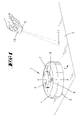
- a device 1 in the form of a suction and / or sweeping device further in the form of a movable household floor cleaning appliance.
- This has a chassis, which to the caring floor 2 facing driven by electric motor Verfahrzier 3 and preferably carries a projecting beyond the lower edge of the chassis floor, also driven by electric motor, not shown in the drawings brush.
- the device 1 is preferably additionally or alternatively provided with a suction device to the brush.
- the chassis is covered by a device hood 4, wherein the device 1 preferably has a circular outline.
- the device 1 As a suction and / or sweeper is further on the DE 102 42 257 A1 directed.
- the content of this patent application is hereby incorporated in full into the disclosure of the present invention, also for the purpose of including features of this patent application in claims of the present invention.
- a preferably relative to the device cover 4 fixed platform 5 is provided on the device hood 4 of the device 1 is with reference to the in Fig. 1 illustrated first embodiment.
- This carries circumferentially preferably three photosensitive elements in the form of light sensors 6 to 8.
- Also preferred is an arrangement of several, preferably uniformly distributed over the entire circumference arranged light sensors, such as, 5, 10 or even 20 light sensors.
- These light sensors 6 to 8 are initially aligned substantially in the usual direction of travel r of the device 1, wherein more preferably viewed in the circumferential direction central light sensor 6 is preferably aligned exactly in the direction of travel r, while the two laterally thereto arranged light sensors 7 and 8 with respect to a central vertical axis x of Device 1 are positioned at an angle of preferably 10 to 30 °, more preferably 15 ° to the central light sensor 6. More preferably, the light sensors 6 to 8 are positioned on a common, aligned parallel to the ground 2 level.
- the platform 5 is rotatable relative to the device cover 4 about the vertical axis x, this further preferably by an electric motor continuously rotatable about the vertical axis x.
- the platform 5 carries in this case only a radially outwardly facing photosensitive element in the form of a light sensor 6, by means of which the rotation of the platform 5 quasi an all-around scanning is achieved.
- the route guidance of the automatically movable device 1 is preferably achieved by means of a light source 9. This is preferably recorded in a remote control 10. This is more preferably a laser pointer with red light (650 nm) or green light (532 nm). In addition, an infrared light source with a wavelength of 980 nm is provided in the laser pointer.
- the laser point directed to the bottom 2 preferably serves as a visual aid for the user, while at the same time an infrared surface which is preferably enlarged relative to the laser spot is thrown onto the bottom 2 , In this case, the laser point is preferably further directed toward the center of the infrared surface.
- the light signal (preferably infrared light signal) to be emitted by the light source 9 is preferably modulated (for example 20 kHz rectangle). Accordingly, a signal is preferably emitted with the light source 9, wherein after reception within the device 1, a signal as in FIG. 3 exemplified electronics for evaluation with the analog signals of the light sensors 6 to 8 is working. A digitization into a signal pattern M (as exemplified in FIGS FIGS. 4 and 5 hereafter) is performed by a microcontroller. The further evaluation of the received light signal is preferably independent of its signal form.
- FIG. 4 shows a typical signal pattern M with a within a period over a period of time existing, constant high level of the signal and a constant over the remaining period of time low-level signal. If threshold values are exceeded or undershot, a high or low state is switched.
- FIG. 5 is another possible signal pattern M shown, in which within a period, the low-level signal is interrupted by high-level signals of the same size. This allows a further coding of the signal.
- Such a signal pattern M requires a phase adjustment, that is, the phase of a reference signal is shifted.
- a reflective light surface 11 is generated for the guidance of the device 1 on the floor 2, which is preferably not visible with the exception of serving for user orientation laser point.
- the device 1 is either via the discretely arranged light sensors 6 to 8 according to the in Fig. 1 illustrated first embodiment or by means of the circumferential light sensor 6 of the second embodiment according to Fig. 2 able to determine the direction to the light spot 11 in order to retrieve from the calculated values a corresponding movement strategy to the illuminated area of the floor 2.
- the distance to the light spot 11 can preferably be determined using a triangulation method.
- the light sensor (s) 6 to 8 and more preferably the respective associated optical components form the receiver.
- a rotary encoder with light barrier is preferably provided in a rotating light sensor 6 according to the second embodiment.
- the angle of rotation of the light sensor 6 or of the platform 5 determined by means of the rotary encoder designed in this way can be used to determine the direction of the signal, in particular the direction of the signal pattern M reflected by the bottom 2, by preferential calculation of a time delay, in particular between the signal generator and the evaluating electronics.
- a determination of the direction of the signal is to be derived from which of the light sensors 6 to 8 has received the strongest signal.
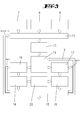
- FIG. 3 Schematically illustrated circuit arrangement provided which relates to the permanently installed arrangement of light sensors 6 to 8 according to the first embodiment in Fig. 1 refers.
- the plurality, preferably three light sensors 6 to 8 (wherein more than three light sensors can also be provided, for example, with uniform distribution over the circumference of the platform 5) are connected by a sensor selection unit 12.
- the filtered-out frequencies are not further amplified accordingly below.
- the remaining after the band pass filter element 13 signals are raised in a preamplifier element 14 to a further processed level.
- the signal is subsequently calculated or processed with a reference pattern (REF 1 , REF 2 ), which is generated by a central control element 15.
- the latter is preferably a microcontroller, which further preferably generates two reference signals REF 1 and REF 2 phase-shifted by 90 ° to one another.
- An amplifier circuit is used per phase, which is preferably switchable with the aid of a multiplexer integrated in the central control element 15 between inverting and non-inverting.
- two phase-sensitive detector elements 16 and 17 are provided, more preferably in the form of lock-in amplifiers.
- pure DC signals are evaluated. To obtain this, is integrated via the output signals of the previous circuit. This is preferably done by using a low-pass filter element 18, 19 with low cut-off frequency. Each phase-sensitive detector element 16, 17 is followed by such a low-pass filter element 18, 19. Also, the phase-sensitive detector element 16, 17 is preferably combined with the low-pass filter element.
- the overall circuit is a very narrow-band bandpass filter. Coupled interference can be reliably suppressed.
- the low-pass filter elements 18, 19 deliver a result to the central control element 15 as a function of the comparison of the signal pattern M to the respective reference signal REF 1 or REF 2.
- a positive result ie if the signal pattern M and the reference signal REF match 1 or REF 2 , used to determine the direction information on the basis of the signal-capturing, activated light sensor.
- a switchover of the light sensors 6 to 8 by means of the sensor selection unit 12 is achieved by the central control element 15 (compare path "sensor ID" in FIG Fig. 3 ).
- the choice of the gain V results from the last determined signal strength at the output of a phase-sensitive detector element 16,17 and from the signal strengths of all sensors. If this signal strength lies below a limit value empirically determined and preferably stored in the central control element 15, then the amplification factor V is increased so as not to lose the signal. If the signal strength is too high, however, an overload of the electronics threatens. In order to prevent this, a sufficiently lower amplification factor V is selected in good time.
- the adjustment of the amplification factors V is preferably made after each measurement, the adjustment preferably being due to all receivers, i. on all light sensors.
- the central control element 15 offers the possibility of matching the transmitter (in this case the light source 9) and the receiver (here the light sensors 6 to 8) to one another by means of a calibration function ("system marriage").
- each low-pass filter element 18, 19 is connected to an offset setting unit 20.
- an offset setting unit 20 At the output of each phase-sensitive detector element 16, 17, negative voltages may occur, which may destroy the central control element 15 or parts thereof. To prevent this, the potentials are raised by the offset setting unit 20 to a voltage of> 0 volts.
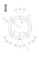
- the above-described electronics in an arrangement of a plurality of light sensors of the light sensor with the strongest signal level can be identified, whereby the correct direction can be determined, in which the device is to proceed.
- a plurality of, in particular adjacent, light sensors for example two adjacent light sensors, to have signal levels that are at least approximately equal to one another (possibly within a predetermined tolerance range).
- the direction of travel of the device is given, for example, by the bisector of the angle enclosing the two light sensors, in particular with two signal levels of equal intensity.
- each light sensor has a detection angle ⁇ of preferably 50 °, alternatively a detection angle of 30 ° to 180 °, wherein the detection ranges can overlap.
- the apparatus 1 When the rear light sensor 21 detects the light spot 11 (stronger signal level to the light sensor 21), the apparatus 1 is caused to rotate by 180 °, followed by a next evaluation for the exact alignment of the device 1 with the three in the direction of travel r arranged light sensors 6 to 8 takes place.
- each sensor is placed as close as possible to an associated electronics in order to obtain no noisy signals. For this it is usually necessary to build at least a part of the electronics several times.
- the proposed solution is a central, locally removed from the light sensors evaluation circuit given. The operation is possible with both a tuned phase and a non-tuned phase. The optical wavelength range can be easily changed by suitable replacement of the light sensors.
- the evaluation principle is based on the electrically converted sensor signals and is thus independent of the type of detector. Only a stable transmission frequency is required. The digitized signal pattern and the signal frequency can also be selected almost freely, since the corresponding reference signal can be specifically reproduced in the central control element 15.
Landscapes
- Physics & Mathematics (AREA)
- Engineering & Computer Science (AREA)
- General Physics & Mathematics (AREA)
- Radar, Positioning & Navigation (AREA)
- Remote Sensing (AREA)
- Electromagnetism (AREA)
- Automation & Control Theory (AREA)
- Aviation & Aerospace Engineering (AREA)
- Theoretical Computer Science (AREA)
- Mathematical Physics (AREA)
- Computing Systems (AREA)
- Control Of Position, Course, Altitude, Or Attitude Of Moving Bodies (AREA)
- Manipulator (AREA)
- Investigating Or Analysing Materials By Optical Means (AREA)
- Geophysics And Detection Of Objects (AREA)
- Length Measuring Devices By Optical Means (AREA)
- Photometry And Measurement Of Optical Pulse Characteristics (AREA)
Applications Claiming Priority (2)
| Application Number | Priority Date | Filing Date | Title |
|---|---|---|---|
| DE102011051397 | 2011-06-28 | ||
| DE102011053386A DE102011053386A1 (de) | 2011-06-28 | 2011-09-08 | Selbsttätig verfahrbares Gerät sowie Verfahren zur Zielführung eines solchen Gerätes |
Publications (3)
| Publication Number | Publication Date |
|---|---|
| EP2541272A2 true EP2541272A2 (fr) | 2013-01-02 |
| EP2541272A3 EP2541272A3 (fr) | 2018-01-10 |
| EP2541272B1 EP2541272B1 (fr) | 2020-07-29 |
Family
ID=46466101
Family Applications (1)
| Application Number | Title | Priority Date | Filing Date |
|---|---|---|---|
| EP12170420.9A Not-in-force EP2541272B1 (fr) | 2011-06-28 | 2012-06-01 | Appareil à déplacement automatique et procédé de guidage routier d'un tel appareil |
Country Status (5)
| Country | Link |
|---|---|
| EP (1) | EP2541272B1 (fr) |
| JP (1) | JP6033579B2 (fr) |
| CN (1) | CN102846280B (fr) |
| DE (1) | DE102011053386A1 (fr) |
| ES (1) | ES2812570T3 (fr) |
Cited By (3)
| Publication number | Priority date | Publication date | Assignee | Title |
|---|---|---|---|---|
| EP3307494A4 (fr) * | 2015-06-09 | 2018-06-20 | Samsung Electronics Co., Ltd. | Robot mobile et son procédé de commande |
| EP3501362A3 (fr) * | 2014-02-28 | 2020-04-08 | Samsung Electronics Co., Ltd. | Robot de nettoyage et télécommande inclus en son sein |
| US12279747B2 (en) | 2020-01-31 | 2025-04-22 | Dyson Technology Limited | Cleaner head for a vacuum cleaner |
Families Citing this family (9)
| Publication number | Priority date | Publication date | Assignee | Title |
|---|---|---|---|---|
| CN104977929B (zh) * | 2014-04-09 | 2019-04-12 | 燕成祥 | 导引式清洁装置与导引式清洁组 |
| TWI635303B (zh) * | 2014-04-09 | 2018-09-11 | 燕成祥 | Guided cleaning device and guided cleaning group |
| CN105302130A (zh) * | 2014-07-28 | 2016-02-03 | 东盛精密科技有限公司 | 移动引导装置及移动引导方法 |
| DE102018102601A1 (de) * | 2018-02-06 | 2019-08-08 | Sick Ag | Optoelektronischer Sensor und Verfahren zur Erfassung von Objekten in einem Überwachungsbereich |
| JP6618087B1 (ja) * | 2018-07-20 | 2019-12-11 | 三菱ロジスネクスト株式会社 | 無人飛行体および無人搬送システム |
| CN109594809B (zh) * | 2018-12-10 | 2020-06-09 | 郑天尧 | 一种游泳池池壁洗擦清洁装置 |
| CN111374606A (zh) * | 2018-12-29 | 2020-07-07 | 尚科宁家(中国)科技有限公司 | 一种扫地机器人 |
| KR102417984B1 (ko) * | 2020-05-11 | 2022-07-08 | 한국생산기술연구원 | 굴삭기의 운전자 보조시스템 및 이를 이용한 굴삭기 제어 방법 |
| CN114515124B (zh) * | 2022-04-21 | 2022-07-22 | 深圳市倍思科技有限公司 | 清洁位置确定方法、装置、设备及存储介质 |
Citations (2)
| Publication number | Priority date | Publication date | Assignee | Title |
|---|---|---|---|---|
| DE10242257A1 (de) | 2001-09-14 | 2003-04-24 | Vorwerk Co Interholding | Selbsttätig verfahrbares Bodenstaub-Aufsammelgerät, sowie Kombination eines derartigen Aufsammelgerätes und einer Basisstation |
| DE102009059215A1 (de) | 2009-08-12 | 2011-02-17 | Vorwerk & Co. Interholding Gmbh | Selbsttätig verfahrbares Gerät sowie Verfahren zur Zielführung eines solchen Gerätes |
Family Cites Families (10)
| Publication number | Priority date | Publication date | Assignee | Title |
|---|---|---|---|---|
| US5051906A (en) * | 1989-06-07 | 1991-09-24 | Transitions Research Corporation | Mobile robot navigation employing retroreflective ceiling features |
| DE9400950U1 (de) * | 1994-01-20 | 1995-08-24 | Selectronic Gesellschaft für Sicherheitstechnik und Sonderelektronik mbH, 14542 Werder | Vorrichtung zur Erfassung lebender Körper sowie deren Verwendung |
| JPH09167017A (ja) * | 1995-12-15 | 1997-06-24 | Howa Mach Ltd | 無人車の走行制御装置 |
| TW529944B (en) * | 2000-12-08 | 2003-05-01 | Family Co Ltd | Massage machine, information recording medium, program writing method for controlling the massage machine |
| FR2820216B1 (fr) * | 2001-01-26 | 2003-04-25 | Wany Sa | Procede et dispositif de detection d'obstacle et de mesure de distance par rayonnement infrarouge |
| KR100520079B1 (ko) * | 2003-08-01 | 2005-10-12 | 삼성전자주식회사 | 로봇시스템 및 그 제어방법 |
| JP4431446B2 (ja) * | 2004-06-08 | 2010-03-17 | シャープ株式会社 | 自走式ロボット |
| US8972052B2 (en) * | 2004-07-07 | 2015-03-03 | Irobot Corporation | Celestial navigation system for an autonomous vehicle |
| CA2578525A1 (fr) * | 2004-08-27 | 2006-03-09 | Sharper Image Corporation | Robot nettoyeur comprenant une unite a depression amelioree |
| US8258453B2 (en) * | 2009-04-29 | 2012-09-04 | Intersil Americas Inc. | Long range proximity and/or motion detector with ambient light detection capabilities |
-
2011
- 2011-09-08 DE DE102011053386A patent/DE102011053386A1/de not_active Withdrawn
-
2012
- 2012-06-01 ES ES12170420T patent/ES2812570T3/es active Active
- 2012-06-01 EP EP12170420.9A patent/EP2541272B1/fr not_active Not-in-force
- 2012-06-13 JP JP2012133542A patent/JP6033579B2/ja not_active Expired - Fee Related
- 2012-06-28 CN CN201210222210.6A patent/CN102846280B/zh not_active Expired - Fee Related
Patent Citations (2)
| Publication number | Priority date | Publication date | Assignee | Title |
|---|---|---|---|---|
| DE10242257A1 (de) | 2001-09-14 | 2003-04-24 | Vorwerk Co Interholding | Selbsttätig verfahrbares Bodenstaub-Aufsammelgerät, sowie Kombination eines derartigen Aufsammelgerätes und einer Basisstation |
| DE102009059215A1 (de) | 2009-08-12 | 2011-02-17 | Vorwerk & Co. Interholding Gmbh | Selbsttätig verfahrbares Gerät sowie Verfahren zur Zielführung eines solchen Gerätes |
Cited By (5)
| Publication number | Priority date | Publication date | Assignee | Title |
|---|---|---|---|---|
| EP3501362A3 (fr) * | 2014-02-28 | 2020-04-08 | Samsung Electronics Co., Ltd. | Robot de nettoyage et télécommande inclus en son sein |
| US10809714B2 (en) | 2014-02-28 | 2020-10-20 | Samsung Electronics Co., Ltd. | Cleaning robot and remote controller included therein |
| US11550316B2 (en) | 2014-02-28 | 2023-01-10 | Samsung Electronics Co., Ltd. | Cleaning robot and remote controller included therein |
| EP3307494A4 (fr) * | 2015-06-09 | 2018-06-20 | Samsung Electronics Co., Ltd. | Robot mobile et son procédé de commande |
| US12279747B2 (en) | 2020-01-31 | 2025-04-22 | Dyson Technology Limited | Cleaner head for a vacuum cleaner |
Also Published As
| Publication number | Publication date |
|---|---|
| DE102011053386A1 (de) | 2013-01-03 |
| CN102846280A (zh) | 2013-01-02 |
| JP6033579B2 (ja) | 2016-11-30 |
| JP2013012193A (ja) | 2013-01-17 |
| ES2812570T3 (es) | 2021-03-17 |
| CN102846280B (zh) | 2017-03-01 |
| EP2541272A3 (fr) | 2018-01-10 |
| EP2541272B1 (fr) | 2020-07-29 |
Similar Documents
| Publication | Publication Date | Title |
|---|---|---|
| EP2541272B1 (fr) | Appareil à déplacement automatique et procédé de guidage routier d'un tel appareil | |
| EP2382516B1 (fr) | Procédé et système de détection de la zone de travail d'un appareil de travail mobile | |
| EP3412191B1 (fr) | Appareil de traitement du sol se déplaçant automatiquement | |
| EP2755101B1 (fr) | Robot automoteur et procédé de détermination de distance pour un robot automoteur | |
| EP2764812B1 (fr) | Robot de nettoyage | |
| DE102009059212A1 (de) | Selbsttätig verfahrbares Gerät sowie Verfahren zur Zielführung eines solchen Gerätes | |
| DE69706935T2 (de) | System und gerät für selbstorientierungsvorrichtung | |
| DE19520532C2 (de) | Verfahren zum schnellen Messen der Richtung von einer autonomen Vorrichtung zu einem Transponder sowie selbstfahrende autonome Vorrichtung #### | |
| DE102020210951B3 (de) | Verfahren zur Überwachung der mechanischen automatisierten Entfernung von Unkräutern | |
| EP1730616B1 (fr) | Système de traitement de surfaces | |
| EP3669245A1 (fr) | Procédé de reconnaissance d'une position d'un véhicule-robot mobile et véhicule-robot et système | |
| EP0970390A1 (fr) | Procede de determination de l'ecart vertical entre un objet et un dispositif a position variable | |
| DE102011051729A1 (de) | Selbstfahrendes Bodenreinigungsgerät | |
| DE102010015941A1 (de) | Verfahren zur Abstandsmessung auf Lichtbasis | |
| EP3559770B1 (fr) | Procédé de fonctionnement d'un appareil de nettoyage à déplacement automatique ainsi qu'un tel appareil de nettoyage | |
| WO2009071379A1 (fr) | Dispositif à fonctionnement autonome | |
| EP0319700A1 (fr) | Aspirateur de poussières mobile | |
| DE102004014281B4 (de) | Flächenbearbeitungssystem | |
| EP1224644B1 (fr) | Dispositif pour reguler le flux de circulation a un carrefour, notamment pour reguler les feux | |
| EP1136027A2 (fr) | Appareil d'entretien de sol ainsi que procede pour reconnaitre un etat du sol respectivement pour aligner le mouvement de conduite | |
| DE102009003748B4 (de) | Bodenstaub-Aufsammelgerät sowie Verfahren eines solchen Geräts | |
| DE102007023156A1 (de) | Zum selbstständigen Betrieb ausgebildetes Roboterfahrzeug | |
| DE102011001035B4 (de) | Selbsttätig verfahrbares Saug- und/oder Kehrgerät sowie Abstandssensor | |
| EP3173815A1 (fr) | Antriebseinrichtung zum antreiben wenigstens eines spiegels eine umlenkspie-gelanordnung, optische messvorrichtung, fahrerassistenzsystem, verfahren zum betreiben einer optischen messvorrichtung | |
| DE102006004865A1 (de) | Parkassistenzsystem für ein Fahrzeug |
Legal Events
| Date | Code | Title | Description |
|---|---|---|---|
| PUAI | Public reference made under article 153(3) epc to a published international application that has entered the european phase |
Free format text: ORIGINAL CODE: 0009012 |
|
| AK | Designated contracting states |
Kind code of ref document: A2 Designated state(s): AL AT BE BG CH CY CZ DE DK EE ES FI FR GB GR HR HU IE IS IT LI LT LU LV MC MK MT NL NO PL PT RO RS SE SI SK SM TR |
|
| AX | Request for extension of the european patent |
Extension state: BA ME |
|
| PUAL | Search report despatched |
Free format text: ORIGINAL CODE: 0009013 |
|
| AK | Designated contracting states |
Kind code of ref document: A3 Designated state(s): AL AT BE BG CH CY CZ DE DK EE ES FI FR GB GR HR HU IE IS IT LI LT LU LV MC MK MT NL NO PL PT RO RS SE SI SK SM TR |
|
| AX | Request for extension of the european patent |
Extension state: BA ME |
|
| RIC1 | Information provided on ipc code assigned before grant |
Ipc: G01S 5/16 20060101ALI20171204BHEP Ipc: G05D 1/00 20060101ALI20171204BHEP Ipc: G01S 3/782 20060101ALI20171204BHEP Ipc: G01S 3/78 20060101AFI20171204BHEP |
|
| STAA | Information on the status of an ep patent application or granted ep patent |
Free format text: STATUS: REQUEST FOR EXAMINATION WAS MADE |
|
| 17P | Request for examination filed |
Effective date: 20180618 |
|
| RBV | Designated contracting states (corrected) |
Designated state(s): AL AT BE BG CH CY CZ DE DK EE ES FI FR GB GR HR HU IE IS IT LI LT LU LV MC MK MT NL NO PL PT RO RS SE SI SK SM TR |
|
| GRAP | Despatch of communication of intention to grant a patent |
Free format text: ORIGINAL CODE: EPIDOSNIGR1 |
|
| STAA | Information on the status of an ep patent application or granted ep patent |
Free format text: STATUS: GRANT OF PATENT IS INTENDED |
|
| INTG | Intention to grant announced |
Effective date: 20200108 |
|
| GRAS | Grant fee paid |
Free format text: ORIGINAL CODE: EPIDOSNIGR3 |
|
| GRAA | (expected) grant |
Free format text: ORIGINAL CODE: 0009210 |
|
| STAA | Information on the status of an ep patent application or granted ep patent |
Free format text: STATUS: THE PATENT HAS BEEN GRANTED |
|
| AK | Designated contracting states |
Kind code of ref document: B1 Designated state(s): AL AT BE BG CH CY CZ DE DK EE ES FI FR GB GR HR HU IE IS IT LI LT LU LV MC MK MT NL NO PL PT RO RS SE SI SK SM TR |
|
| REG | Reference to a national code |
Ref country code: GB Ref legal event code: FG4D Free format text: NOT ENGLISH |
|
| REG | Reference to a national code |
Ref country code: CH Ref legal event code: EP |
|
| REG | Reference to a national code |
Ref country code: DE Ref legal event code: R096 Ref document number: 502012016243 Country of ref document: DE |
|
| REG | Reference to a national code |
Ref country code: AT Ref legal event code: REF Ref document number: 1296425 Country of ref document: AT Kind code of ref document: T Effective date: 20200815 |
|
| REG | Reference to a national code |
Ref country code: IE Ref legal event code: FG4D Free format text: LANGUAGE OF EP DOCUMENT: GERMAN |
|
| REG | Reference to a national code |
Ref country code: LT Ref legal event code: MG4D |
|
| REG | Reference to a national code |
Ref country code: NL Ref legal event code: MP Effective date: 20200729 |
|
| PG25 | Lapsed in a contracting state [announced via postgrant information from national office to epo] |
Ref country code: LT Free format text: LAPSE BECAUSE OF FAILURE TO SUBMIT A TRANSLATION OF THE DESCRIPTION OR TO PAY THE FEE WITHIN THE PRESCRIBED TIME-LIMIT Effective date: 20200729 Ref country code: HR Free format text: LAPSE BECAUSE OF FAILURE TO SUBMIT A TRANSLATION OF THE DESCRIPTION OR TO PAY THE FEE WITHIN THE PRESCRIBED TIME-LIMIT Effective date: 20200729 Ref country code: NO Free format text: LAPSE BECAUSE OF FAILURE TO SUBMIT A TRANSLATION OF THE DESCRIPTION OR TO PAY THE FEE WITHIN THE PRESCRIBED TIME-LIMIT Effective date: 20201029 Ref country code: SE Free format text: LAPSE BECAUSE OF FAILURE TO SUBMIT A TRANSLATION OF THE DESCRIPTION OR TO PAY THE FEE WITHIN THE PRESCRIBED TIME-LIMIT Effective date: 20200729 Ref country code: FI Free format text: LAPSE BECAUSE OF FAILURE TO SUBMIT A TRANSLATION OF THE DESCRIPTION OR TO PAY THE FEE WITHIN THE PRESCRIBED TIME-LIMIT Effective date: 20200729 Ref country code: PT Free format text: LAPSE BECAUSE OF FAILURE TO SUBMIT A TRANSLATION OF THE DESCRIPTION OR TO PAY THE FEE WITHIN THE PRESCRIBED TIME-LIMIT Effective date: 20201130 Ref country code: BG Free format text: LAPSE BECAUSE OF FAILURE TO SUBMIT A TRANSLATION OF THE DESCRIPTION OR TO PAY THE FEE WITHIN THE PRESCRIBED TIME-LIMIT Effective date: 20201029 Ref country code: GR Free format text: LAPSE BECAUSE OF FAILURE TO SUBMIT A TRANSLATION OF THE DESCRIPTION OR TO PAY THE FEE WITHIN THE PRESCRIBED TIME-LIMIT Effective date: 20201030 |
|
| PG25 | Lapsed in a contracting state [announced via postgrant information from national office to epo] |
Ref country code: RS Free format text: LAPSE BECAUSE OF FAILURE TO SUBMIT A TRANSLATION OF THE DESCRIPTION OR TO PAY THE FEE WITHIN THE PRESCRIBED TIME-LIMIT Effective date: 20200729 Ref country code: LV Free format text: LAPSE BECAUSE OF FAILURE TO SUBMIT A TRANSLATION OF THE DESCRIPTION OR TO PAY THE FEE WITHIN THE PRESCRIBED TIME-LIMIT Effective date: 20200729 Ref country code: PL Free format text: LAPSE BECAUSE OF FAILURE TO SUBMIT A TRANSLATION OF THE DESCRIPTION OR TO PAY THE FEE WITHIN THE PRESCRIBED TIME-LIMIT Effective date: 20200729 Ref country code: IS Free format text: LAPSE BECAUSE OF FAILURE TO SUBMIT A TRANSLATION OF THE DESCRIPTION OR TO PAY THE FEE WITHIN THE PRESCRIBED TIME-LIMIT Effective date: 20201129 |
|
| REG | Reference to a national code |
Ref country code: ES Ref legal event code: FG2A Ref document number: 2812570 Country of ref document: ES Kind code of ref document: T3 Effective date: 20210317 |
|
| PG25 | Lapsed in a contracting state [announced via postgrant information from national office to epo] |
Ref country code: NL Free format text: LAPSE BECAUSE OF FAILURE TO SUBMIT A TRANSLATION OF THE DESCRIPTION OR TO PAY THE FEE WITHIN THE PRESCRIBED TIME-LIMIT Effective date: 20200729 |
|
| PG25 | Lapsed in a contracting state [announced via postgrant information from national office to epo] |
Ref country code: RO Free format text: LAPSE BECAUSE OF FAILURE TO SUBMIT A TRANSLATION OF THE DESCRIPTION OR TO PAY THE FEE WITHIN THE PRESCRIBED TIME-LIMIT Effective date: 20200729 Ref country code: SM Free format text: LAPSE BECAUSE OF FAILURE TO SUBMIT A TRANSLATION OF THE DESCRIPTION OR TO PAY THE FEE WITHIN THE PRESCRIBED TIME-LIMIT Effective date: 20200729 Ref country code: DK Free format text: LAPSE BECAUSE OF FAILURE TO SUBMIT A TRANSLATION OF THE DESCRIPTION OR TO PAY THE FEE WITHIN THE PRESCRIBED TIME-LIMIT Effective date: 20200729 Ref country code: EE Free format text: LAPSE BECAUSE OF FAILURE TO SUBMIT A TRANSLATION OF THE DESCRIPTION OR TO PAY THE FEE WITHIN THE PRESCRIBED TIME-LIMIT Effective date: 20200729 |
|
| REG | Reference to a national code |
Ref country code: DE Ref legal event code: R097 Ref document number: 502012016243 Country of ref document: DE |
|
| PG25 | Lapsed in a contracting state [announced via postgrant information from national office to epo] |
Ref country code: AL Free format text: LAPSE BECAUSE OF FAILURE TO SUBMIT A TRANSLATION OF THE DESCRIPTION OR TO PAY THE FEE WITHIN THE PRESCRIBED TIME-LIMIT Effective date: 20200729 |
|
| PLBE | No opposition filed within time limit |
Free format text: ORIGINAL CODE: 0009261 |
|
| STAA | Information on the status of an ep patent application or granted ep patent |
Free format text: STATUS: NO OPPOSITION FILED WITHIN TIME LIMIT |
|
| PG25 | Lapsed in a contracting state [announced via postgrant information from national office to epo] |
Ref country code: SK Free format text: LAPSE BECAUSE OF FAILURE TO SUBMIT A TRANSLATION OF THE DESCRIPTION OR TO PAY THE FEE WITHIN THE PRESCRIBED TIME-LIMIT Effective date: 20200729 |
|
| 26N | No opposition filed |
Effective date: 20210430 |
|
| PG25 | Lapsed in a contracting state [announced via postgrant information from national office to epo] |
Ref country code: SI Free format text: LAPSE BECAUSE OF FAILURE TO SUBMIT A TRANSLATION OF THE DESCRIPTION OR TO PAY THE FEE WITHIN THE PRESCRIBED TIME-LIMIT Effective date: 20200729 |
|
| PG25 | Lapsed in a contracting state [announced via postgrant information from national office to epo] |
Ref country code: MC Free format text: LAPSE BECAUSE OF FAILURE TO SUBMIT A TRANSLATION OF THE DESCRIPTION OR TO PAY THE FEE WITHIN THE PRESCRIBED TIME-LIMIT Effective date: 20200729 Ref country code: CZ Free format text: LAPSE BECAUSE OF NON-PAYMENT OF DUE FEES Effective date: 20210601 |
|
| REG | Reference to a national code |
Ref country code: CH Ref legal event code: PL |
|
| GBPC | Gb: european patent ceased through non-payment of renewal fee |
Effective date: 20210601 |
|
| REG | Reference to a national code |
Ref country code: BE Ref legal event code: MM Effective date: 20210630 |
|
| PG25 | Lapsed in a contracting state [announced via postgrant information from national office to epo] |
Ref country code: LU Free format text: LAPSE BECAUSE OF NON-PAYMENT OF DUE FEES Effective date: 20210601 |
|
| PG25 | Lapsed in a contracting state [announced via postgrant information from national office to epo] |
Ref country code: LI Free format text: LAPSE BECAUSE OF NON-PAYMENT OF DUE FEES Effective date: 20210630 Ref country code: IE Free format text: LAPSE BECAUSE OF NON-PAYMENT OF DUE FEES Effective date: 20210601 Ref country code: GB Free format text: LAPSE BECAUSE OF NON-PAYMENT OF DUE FEES Effective date: 20210601 Ref country code: CH Free format text: LAPSE BECAUSE OF NON-PAYMENT OF DUE FEES Effective date: 20210630 |
|
| PG25 | Lapsed in a contracting state [announced via postgrant information from national office to epo] |
Ref country code: BE Free format text: LAPSE BECAUSE OF NON-PAYMENT OF DUE FEES Effective date: 20210630 |
|
| REG | Reference to a national code |
Ref country code: AT Ref legal event code: MM01 Ref document number: 1296425 Country of ref document: AT Kind code of ref document: T Effective date: 20210601 |
|
| PG25 | Lapsed in a contracting state [announced via postgrant information from national office to epo] |
Ref country code: AT Free format text: LAPSE BECAUSE OF NON-PAYMENT OF DUE FEES Effective date: 20210601 |
|
| PG25 | Lapsed in a contracting state [announced via postgrant information from national office to epo] |
Ref country code: HU Free format text: LAPSE BECAUSE OF FAILURE TO SUBMIT A TRANSLATION OF THE DESCRIPTION OR TO PAY THE FEE WITHIN THE PRESCRIBED TIME-LIMIT; INVALID AB INITIO Effective date: 20120601 Ref country code: CY Free format text: LAPSE BECAUSE OF FAILURE TO SUBMIT A TRANSLATION OF THE DESCRIPTION OR TO PAY THE FEE WITHIN THE PRESCRIBED TIME-LIMIT Effective date: 20200729 |
|
| P01 | Opt-out of the competence of the unified patent court (upc) registered |
Effective date: 20230517 |
|
| PGFP | Annual fee paid to national office [announced via postgrant information from national office to epo] |
Ref country code: FR Payment date: 20230620 Year of fee payment: 12 Ref country code: DE Payment date: 20230620 Year of fee payment: 12 |
|
| PGFP | Annual fee paid to national office [announced via postgrant information from national office to epo] |
Ref country code: IT Payment date: 20230630 Year of fee payment: 12 Ref country code: ES Payment date: 20230719 Year of fee payment: 12 |
|
| PG25 | Lapsed in a contracting state [announced via postgrant information from national office to epo] |
Ref country code: MK Free format text: LAPSE BECAUSE OF FAILURE TO SUBMIT A TRANSLATION OF THE DESCRIPTION OR TO PAY THE FEE WITHIN THE PRESCRIBED TIME-LIMIT Effective date: 20200729 |
|
| PG25 | Lapsed in a contracting state [announced via postgrant information from national office to epo] |
Ref country code: TR Free format text: LAPSE BECAUSE OF FAILURE TO SUBMIT A TRANSLATION OF THE DESCRIPTION OR TO PAY THE FEE WITHIN THE PRESCRIBED TIME-LIMIT Effective date: 20200729 |
|
| PG25 | Lapsed in a contracting state [announced via postgrant information from national office to epo] |
Ref country code: MT Free format text: LAPSE BECAUSE OF FAILURE TO SUBMIT A TRANSLATION OF THE DESCRIPTION OR TO PAY THE FEE WITHIN THE PRESCRIBED TIME-LIMIT Effective date: 20200729 |
|
| REG | Reference to a national code |
Ref country code: DE Ref legal event code: R119 Ref document number: 502012016243 Country of ref document: DE |
|
| PG25 | Lapsed in a contracting state [announced via postgrant information from national office to epo] |
Ref country code: DE Free format text: LAPSE BECAUSE OF NON-PAYMENT OF DUE FEES Effective date: 20250101 |
|
| PG25 | Lapsed in a contracting state [announced via postgrant information from national office to epo] |
Ref country code: FR Free format text: LAPSE BECAUSE OF NON-PAYMENT OF DUE FEES Effective date: 20240630 |
|
| PG25 | Lapsed in a contracting state [announced via postgrant information from national office to epo] |
Ref country code: IT Free format text: LAPSE BECAUSE OF NON-PAYMENT OF DUE FEES Effective date: 20240601 |
|
| REG | Reference to a national code |
Ref country code: ES Ref legal event code: FD2A Effective date: 20250728 |
|
| PG25 | Lapsed in a contracting state [announced via postgrant information from national office to epo] |
Ref country code: ES Free format text: LAPSE BECAUSE OF NON-PAYMENT OF DUE FEES Effective date: 20240602 |