EP2541462A2 - Procédé et appareil permettant de réduire la durée de sondage multiprotocole NFC et la consommation d'énergie - Google Patents
Procédé et appareil permettant de réduire la durée de sondage multiprotocole NFC et la consommation d'énergie Download PDFInfo
- Publication number
- EP2541462A2 EP2541462A2 EP12004737A EP12004737A EP2541462A2 EP 2541462 A2 EP2541462 A2 EP 2541462A2 EP 12004737 A EP12004737 A EP 12004737A EP 12004737 A EP12004737 A EP 12004737A EP 2541462 A2 EP2541462 A2 EP 2541462A2
- Authority
- EP
- European Patent Office
- Prior art keywords
- nfc
- modulation
- polling
- type
- polling command
- Prior art date
- Legal status (The legal status is an assumption and is not a legal conclusion. Google has not performed a legal analysis and makes no representation as to the accuracy of the status listed.)
- Granted
Links
Images


Classifications
-
- G—PHYSICS
- G06—COMPUTING OR CALCULATING; COUNTING
- G06K—GRAPHICAL DATA READING; PRESENTATION OF DATA; RECORD CARRIERS; HANDLING RECORD CARRIERS
- G06K7/00—Methods or arrangements for sensing record carriers, e.g. for reading patterns
- G06K7/10—Methods or arrangements for sensing record carriers, e.g. for reading patterns by electromagnetic radiation, e.g. optical sensing; by corpuscular radiation
- G06K7/10009—Methods or arrangements for sensing record carriers, e.g. for reading patterns by electromagnetic radiation, e.g. optical sensing; by corpuscular radiation sensing by radiation using wavelengths larger than 0.1 mm, e.g. radio-waves or microwaves
- G06K7/10118—Methods or arrangements for sensing record carriers, e.g. for reading patterns by electromagnetic radiation, e.g. optical sensing; by corpuscular radiation sensing by radiation using wavelengths larger than 0.1 mm, e.g. radio-waves or microwaves the sensing being preceded by at least one preliminary step
- G06K7/10138—Methods or arrangements for sensing record carriers, e.g. for reading patterns by electromagnetic radiation, e.g. optical sensing; by corpuscular radiation sensing by radiation using wavelengths larger than 0.1 mm, e.g. radio-waves or microwaves the sensing being preceded by at least one preliminary step the step consisting of determining the type of record carrier, e.g. to determine if the record carrier is an RFID tag of the long or short range type, or to determine the preferred communication protocol of the RFID tag
-
- G—PHYSICS
- G06—COMPUTING OR CALCULATING; COUNTING
- G06K—GRAPHICAL DATA READING; PRESENTATION OF DATA; RECORD CARRIERS; HANDLING RECORD CARRIERS
- G06K7/00—Methods or arrangements for sensing record carriers, e.g. for reading patterns
- G06K7/10—Methods or arrangements for sensing record carriers, e.g. for reading patterns by electromagnetic radiation, e.g. optical sensing; by corpuscular radiation
- G06K7/10009—Methods or arrangements for sensing record carriers, e.g. for reading patterns by electromagnetic radiation, e.g. optical sensing; by corpuscular radiation sensing by radiation using wavelengths larger than 0.1 mm, e.g. radio-waves or microwaves
- G06K7/10237—Methods or arrangements for sensing record carriers, e.g. for reading patterns by electromagnetic radiation, e.g. optical sensing; by corpuscular radiation sensing by radiation using wavelengths larger than 0.1 mm, e.g. radio-waves or microwaves the reader and the record carrier being capable of selectively switching between reader and record carrier appearance, e.g. in near field communication [NFC] devices where the NFC device may function as an RFID reader or as an RFID tag
-
- G—PHYSICS
- G06—COMPUTING OR CALCULATING; COUNTING
- G06K—GRAPHICAL DATA READING; PRESENTATION OF DATA; RECORD CARRIERS; HANDLING RECORD CARRIERS
- G06K7/00—Methods or arrangements for sensing record carriers, e.g. for reading patterns
- G06K7/10—Methods or arrangements for sensing record carriers, e.g. for reading patterns by electromagnetic radiation, e.g. optical sensing; by corpuscular radiation
- G06K7/10009—Methods or arrangements for sensing record carriers, e.g. for reading patterns by electromagnetic radiation, e.g. optical sensing; by corpuscular radiation sensing by radiation using wavelengths larger than 0.1 mm, e.g. radio-waves or microwaves
- G06K7/10297—Methods or arrangements for sensing record carriers, e.g. for reading patterns by electromagnetic radiation, e.g. optical sensing; by corpuscular radiation sensing by radiation using wavelengths larger than 0.1 mm, e.g. radio-waves or microwaves arrangements for handling protocols designed for non-contact record carriers such as RFIDs NFCs, e.g. ISO/IEC 14443 and 18092
Definitions
- the invention relates to near field communications (NFC), and more specifically to reducing the multi-protocol polling duration, and thereby power consumption, for a polling NFC device.
- NFC near field communications
- NFC Near field communication
- NFC devices require that NFC devices be present within a relatively small distance from one another so that their corresponding magnetic fields can exchange information. Ranges of up to several centimeters (generally a maximum of 0.1 meter) are common for NFC devices.
- a first NFC device transmits or generates a magnetic field modulated with the information, such as credit information or ticket fare information. This magnetic field inductively couples onto a second NFC device that is proximate to the first NFC device.
- the second NFC device may respond to the first NFC device by transmitting or generating its own modulated magnetic field and inductively coupling this magnetic field to the first NFC device.
- a NFC reader is a type of NFC device that is capable of operating in an initiator mode to initiate a communication with another NFC enabled device.
- a NFC tag is a type of NFC device that is capable operating in a target mode to respond to the initiation of a communication by another NFC enabled device.
- a NFC communicator is a type of NFC device that is capable of operating in the initiator mode or in the target mode and is capable of switching between these two modes.
- the NFC reader or the NFC communicator In a conventional polling procedure, the NFC reader or the NFC communicator generates a magnetic field and probes the magnetic field for the NFC tag or another NFC communicator.
- the conventional polling procedure contemplates multiple technologies, including Type A technology, Type B technology, and Type F (FeliCa) technology.
- the differences between the different technologies include modulation methods, coding schemes, and protocol initialization procedures.
- NFC Forum NFC Activity Specification: Technical Specification, NFC ForumTM Activity 1.0 NFCForum-TS-Activity-1.0," published November 18, 2010 (hereinafter the "NFC Activity Specification”)
- NFC Forum NFC Digital Protocol: Technical Specification, NFC ForumTM Digital 1.0 NFCForum-TS-DigitalProtocol-1.0,” published November 17, 2010 (hereinafter the "NFC Digital Protocol”), which are incorporated by reference herein in their entirety.
- the conventional polling procedure requires the NFC reader or the NFC communicator to initially generate the magnetic field for between 5 ms and 20 ms, conventionally referred to as a guard time, depending on the type of tag technology being used.
- Generation of the magnetic field for a duration of the guard time can use a high amount of current, conventionally, up to 250 mA to generate the magnetic field.
- the guard time is required before transmission of a polling command for each type of technology - 5 ms for Type A and as well as for B, and 20 ms for Type F.
- What is needed is a method and an apparatus to probe the magnetic field for NFC devices of differing technology types which reduces the duration that the magnetic field that is generated before sending the polling command to decrease the amount of power consumed during the polling procedure.
- a method for detecting a Near Field Communication (NFC) device comprises:
- the method further comprises:
- the method further comprises:
- the first polling command is directed to a Type B NFC technology tag
- the second polling command is directed to a Type A NFC technology tag
- the first polling command is directed to a Type F NFC technology tag
- the second polling command is directed to a Type A NFC technology tag
- the first modulation is a 10% amplitude modulation
- the second modulation is a 100% amplitude modulation
- the first modulation is less than 100% amplitude modulation
- the second modulation is a 100% amplitude modulation
- an apparatus for detecting a Near Field Communication (NFC) device comprises:
- the first device is further configured to:
- the first polling command is directed to a Type B NFC technology tag
- the second polling command is directed to a Type A NFC technology tag
- the first polling command is directed to a Type F NFC technology tag
- the second polling command is directed to a Type A NFC technology tag
- the first modulation is a 10% amplitude modulation
- the second modulation is a 100% amplitude modulation
- the first modulation is less than 100% amplitude modulation
- the second modulation is a 100% amplitude modulation
- Embodiments of the invention may be implemented in hardware, firmware, software, or any combination thereof. Embodiments of the invention may also be implemented as instructions stored on a machine-readable medium, which may be read and executed by one or more processors.
- a machine-readable medium may include any mechanism for storing or transmitting information in a form readable by a machine (e.g., a computing device).
- a machine-readable medium may include read only memory (ROM); random access memory (RAM); magnetic disk storage media; optical storage media; flash memory devices; electrical, optical, acoustical or other forms of propagated signals (e.g., carrier waves, infrared signals, digital signals, etc.), and others.
- firmware, software, routines, instructions may be described herein as performing certain actions. However, it should be appreciated that such descriptions are merely for convenience and that such actions in fact result from computing devices, processors, controllers, or other devices executing the firmware, software, routines, instructions, etc.
- FIG. 1 illustrates a block diagram of a NFC environment according to an exemplary embodiment of the invention.
- a NFC environment 100 provides wireless communication of information, such as one or more commands and/or data, among a first NFC device 102 and a second NFC device 104 that are sufficiently proximate to each other.
- the first NFC device 102 and/or the second NFC device 104 may be implemented as a standalone or a discrete device or may be incorporated within or coupled to another electrical device or host device such as a mobile telephone, a portable computing device, another computing device such as a laptop, or a desktop computer, a computer peripheral such as a printer, a portable audio and/or video player, a payment system, a ticketing writing system such as a parking ticketing system, a bus ticketing system, a train ticketing system or an entrance ticketing system to provide some examples, or in a ticket reading system, a toy, a game, a poster, packaging, advertising material, a product inventory checking system and/or any other suitable electronic device that will be apparent to those skilled in the relevant art(s) without departing from the spirit and scope of the invention.
- another electrical device or host device such as a mobile telephone, a portable computing device, another computing device such as a laptop, or a desktop computer, a computer peripheral such as a printer, a portable audio and
- the first NFC device 102 generates a magnetic field and probes the magnetic field for the second NFC device 104.
- the second NFC device 104 may be implemented using a Type A technology, a Type B technology, or a Type F technology.
- Type A and Type B technology are further defined in the NFC Activity Specification and/or ISO/IEC 14443-3, "Identification cards - Contactless integrated circuit(s) cards -Proximity cards -Part 3: Initialization and anticollision," published on June 11, 1999, which is incorporated herein by reference in its entirety.
- Type F technology is further defined in the NFC Activity Specification, which is incorporated by reference herein in its entirety.
- Various conventional polling procedures to probe the magnetic field for these technology types are discussed below.
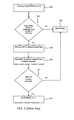
- FIG. 2 illustrates conventional operational steps for polling for Type A NFC technology tags.
- a NFC reader initializes a flag FOUND_A to 0.
- the NFC reader determines whether it is configured to poll for Type A NFC technology tags. If the NFC reader is configured to poll for Type A NFC technology tags, then the conventional operation continues to step 207. Otherwise, the NFC reader ends the polling procedure in step 205.
- the NFC reader generates a magnetic field without a polling command, commonly referred to as an unmodulated carrier field.
- the unmodulated carrier field must be maintained for at least the amount of time that is specified by the NFC Digital Protocol to allow for any Type A NFC technology tags within the unmodulated carrier field to derive or harvest sufficient power to communicate. This required period of time, the guard time, is set at a minimum of 5 ms for Type A technology.
- the NFC reader transmits the polling command using the magnetic field, commonly referred to as a modulated carrier field, to Type A NFC technology tags that may be within the magnetic field.
- the polling command lasts for 86 microseconds. Only those tags that are Type A NFC technology tags will provide a response to the polling command.
- the NFC reader waits 100 microseconds for the response from the Type A NFC technology tags.
- step 211 if the NFC reader has not received a response from any Type A NFC technology tags, the NFC reader ends polling by moving to step 205. Otherwise, if the NFC reader has received a response from a Type A NFC technology tag, the conventional operation proceeds to step 213.
- the NFC reader sets the flag FOUND_A equal to 1, and ends polling and begins communicating with the detected device(s).
- the operational steps for polling for Type B and Type F NFC technology tags is substantially similar to those for Type A. Similar to the guard time for Type A NFC technology tags, the guard time for Type B NFC technology tags is a minimum of 5 ms. However, the guard time for Type F NFC technology tags is a minimum of 20 ms.
- the NFC Activity Specification provides a conventional polling loop for a NFC reader to detect a tag that may be of any particular technology type (A, B, or F).
- the conventional polling loop checks first for Type A NFC technology tags, then Type B NFC technology tags, then Type F NFC technology tags, and then allows for polling for any other tags based on proprietary technology.
- FIG. 3 illustrates a conventional polling loop 300 for polling for Type A, B, and F NFC technology tags.
- the NFC reader initializes the flags FOUND_A, FOUND_B, and FOUND_F to 0.
- the NFC reader determines whether it is configured to poll for Type A NFC technology tags. If the NFC reader is configured to poll for Type A NFC technology tags, then the NFC reader continues to step 305. Otherwise, the NFC reader proceeds to step 315 to begin polling for Type B NFC technology tags.
- the NFC reader generates the unmodulated carrier field.
- the unmodulated carrier field must be maintained for at least the guard time of 5 ms to allow for any NFC tags within the unmodulated carrier field to derive or harvest sufficient power to communicate.
- the NFC reader modulates the carrier field with the polling command for Type A NFC technology tags.
- the polling command lasts for 86 microseconds. Only those tags that are Type A NFC technology tags will provide a response to the polling command.
- the NFC reader waits 100 microseconds for the response from the Type A NFC technology tags.
- step 309 if the NFC reader has not received a response from any Type A NFC technology tag, the NFC reader ends polling for Type A NFC technology tags and proceeds to step 315 to begin polling for Type B NFC technology tags. Otherwise, if the NFC reader has received a response from a Type A NFC technology tag, the conventional polling loop 300 proceeds to step 311. At step 311, because the NFC reader has received a response, it sets the flag FOUND_A equal to 1.
- the NFC reader checks whether it has been configured to bail out after detecting one or more Type A NFC technology tags.
- the NFC reader has been configured to bail out upon detecting one or more Type A NFC technology tags when a flag CON_BAIL_OUT_A has been set equal to 1.
- the NFC reader proceeds to step 343 to end the polling procedure and begins communicating with the detected device(s). If the flag CON_BAIL_OUT_A has not been set equal to 1, then the conventional polling loop 300 proceeds to step 315 to begin polling for Type B NFC technology tags.
- the NFC reader determines whether it is configured to poll for Type B NFC technology tags. If the NFC reader is configured to poll for Type B NFC technology tags, then the NFC reader continues to step 317. Otherwise, the NFC reader ends the polling procedure for Type B NFC technology tags and moves to step 325.
- the NFC reader generates the unmodulated carrier field.
- the unmodulated carrier field must be maintained for at least the guard time of 5 ms to allow for any Type B NFC technology tags within the unmodulated carrier field to derive or harvest sufficient power to communicate.
- the NFC reader modulates the carrier field with the polling command for Type B NFC technology tags.
- the polling command lasts for 86 microseconds. Only those tags that are Type B NFC technology tags will provide a response to the polling command.
- the NFC reader waits 100 microseconds for the response from the Type B NFC technology tags.
- step 321 if the NFC reader has not received a response from any Type B NFC technology tag, the NFC reader ends polling for Type B NFC technology tags and proceeds to step 325. Otherwise, if the NFC reader has received a response from one or more Type B NFC technology tags, the conventional polling loop 300 proceeds to step 323. At step 323, because the NFC reader has received a response, it sets the flag FOUND_B equal to 1.
- the NFC reader checks whether it has been configured to bail out after detecting one or more Type B NFC technology tags.
- the NFC reader has been configured to bail out upon detecting one or more Type B NFC technology tags when a flag CON_BAIL_OUT_B has been set equal to 1.
- the NFC reader proceeds to step 327 to end the polling procedure and begins communicating with the detected device(s). If the flag CON_BAIL_OUT_A has not been set equal to 1, then the conventional polling loop 300 proceeds to step 327.
- the NFC reader checks if either the flag FOUND_A or the flag FOUND_B has been set to 1. If either has been set to 1, the conventional polling loop 300 proceeds to step 343 to end the polling procedure. If neither the flag FOUND_A nor the flag FOUND_B has been set to 1, then the conventional polling loop 300 proceeds to begin polling for Type F NFC technology tags at step 329.
- the NFC reader determines whether it is configured to poll for Type F NFC technology tags. If the NFC reader is configured to poll for Type F NFC technology tags, then the NFC reader continues to step 331. Otherwise, the NFC reader ends the polling procedure for Type F NFC technology and moves to step 339.
- the NFC reader generates the unmodulated carrier field.
- the unmodulated carrier field must be maintained for at least the guard time of 20 ms to allow for any Type F NFC technology tags within the unmodulated carrier field to derive or harvest sufficient power to communicate.
- the NFC reader modulates the carrier field with the polling command for Type F NFC technology tags.
- the polling command lasts for 86 microseconds. Only those tags that are Type F NFC technology tags will provide a response to the polling command.
- the NFC reader waits 100 microseconds for the response from the Type F NFC technology tags.
- step 335 if the NFC reader has not received a response from any Type F NFC technology tag, the NFC reader ends polling for Type F NFC technology tags and proceeds to step 339. Otherwise, if the NFC reader has received a response from a Type F NFC technology tag, the conventional polling loop 300 proceeds to step 337.
- step 337 because the NFC reader has received a response, it sets the flag FOUND_F equal to 1.
- the NFC reader checks if the flag FOUND_A, the flag FOUND_B, or the flag FOUND_F has been set to 1. If any of these has been set to 1, the conventional polling loop 300 proceeds to step 343 to end the polling procedure. If none of them have been set to 1, then the conventional polling loop 300 proceeds to begin polling for proprietary tags at step 341.
- Step 341 includes checking for whether the NFC reader has been configured to poll for proprietary tags. If the NFC reader has been configured to poll for proprietary tags, then the NFC reader waits for the guard time specified by the proprietary technology. The NFC Activity Specification does not contemplate the proprietary processing and parameters as within its scope, and therefore is not included in this specification. After the NFC reader, if necessary, completes polling for proprietary tags, it concludes polling at step 343.
- the NFC reader when the conventional polling loop 300 checks for both Type A and Type B NFC technology tags, the NFC reader generates the magnetic field for 10,372 ⁇ s.
- Type A, Type B, and Type F technologies may be characterized as having different modulation methods, coding schemes, and protocol initialization procedures to provide some examples.
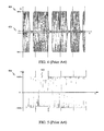
- FIG. 4 illustrates a conventional coding and modulation scheme used on polling signals for Type A NFC technology tags.
- This conventional scheme uses a modified form of Miller coding with 100% Amplitude Shift Keying (ASK) modulation.
- ASK Amplitude Shift Keying
- Type A NFC technology tags recognize the modulation when the amplitude of the polling signal changes by over 95%, as shown in FIG. 4 .
- FIG. 5 illustrates a conventional coding and modulation scheme used on polling signals for Type B NFC technology tags.
- This scheme uses NRZ-L coding with 10% ASK modulation.
- Type B NFC technology tags recognize modulation when the amplitude of the polling signal changes by 10%. No modulation exists at voltage amplitude 501, or 100% amplitude. A state of modulation exists when the polling signal is at voltage amplitude 503, or 90% amplitude.
- Type B NFC technology tags recognize a polling signal when the amplitude varies by 10% from the no modulation state.
- FIG. 6 illustrates a conventional coding and modulation scheme used on polling signals for Type F NFC technology tags.
- This scheme uses Manchester coding with less than 100% ASK modulation.
- Type F NFC technology tags recognize modulation when the amplitude of the polling signal changes by less than that used in the modulation for Type A NFC technology tags. No modulation exists at voltage amplitude 601, or 100% amplitude. Modulation exists when the polling signal is at voltage amplitude 603.
- Type F NFC technology tags recognize a polling signal as modulated when the amplitude varies by less than 100% from the no modulation state.
- the present invention arranges the polling loop so that the NFC reader first polls for tags that use less than 100% ASK modulation, and then polls for tags that use 100% ASK modulation.
- the tags that use 100% ASK modulation view the first poll for tags that use less than 100% ASK modulation as essentially a long guard time, thus eliminating the need for a second guard time before polling for the tags that use 100% ASK modulation.
- FIG. 7 illustrates a method of multi-protocol polling of NFC devices according to an exemplary embodiment of the invention.
- the invention is not limited to this description. Rather, it will be apparent to persons skilled in the relevant art(s) from the teachings herein that other multi-protocol polling methods are within the scope and spirit of the present invention. The following discussion describes the steps in FIG. 7 .
- a first NFC device such as the first NFC device 102 to provide an example, generates the unmodulated carrier field to allow a second NFC device, such as the second NFC device 104 to provide an example, to reset from any previous spurious commands.
- the first NFC device maintains the unmodulated carrier field for a first time period to enable the second NFC device to derive or harvest power to allow communication between the devices.
- the first NFC device transmits a first polling command using a first modulation scheme on the carrier field, typically according to a first protocol, to provide the modulated carrier field.
- This first modulation scheme is characterized by a first amplitude. If the second NFC device is responsive to a different modulation scheme that has a second amplitude that is greater than the first amplitude, it will not recognize the modulated carrier field as including the first polling command. Rather, the modulated carrier field will appear to the second NFC device as being the unmodulated carrier field from which the second NFC device will be able to derive or harvest power.
- the first NFC device continues to provide the unmodulated carrier field for a second time period to detect any response to the first polling command.
- the first NFC device transmits a second polling command using the second modulation scheme on the carrier field, typically according to a second protocol, to provide the modulated carrier field upon expiration of the second time period.
- This second modulation scheme is characterized by a second amplitude that is greater than the first amplitude.
- the first NFC device continues to provide the unmodulated carrier field for a third time period to detect any response to the second polling command.
- the first NFC device then ends the polling procedure and turns the carrier field off if it did not detect any devices.
- FIG. 8 illustrates a first polling procedure used by a first NFC device to poll for a second NFC device according to an exemplary embodiment of the invention.
- a first NFC device 801 polls for a second NFC device 803 using a first polling procedure.
- the first NFC device 801 and the second NFC device 803 may represent an exemplary embodiment of the first NFC device 102 and the second NFC device 104, respectively.
- the first NFC device 801 generates the unmodulated carrier field 805 for a first time period to allow the second NFC device 803 sufficient time to derive or harvest sufficient power to communicate.
- the first NFC device 801 modulates a polling command onto the unmodulated carrier field using a first modulation scheme to provide a modulated carrier field 807.
- the first NFC device 801 generates the unmodulated carrier field 809 for a second time period to allow the second NFC device 803 sufficient time to derive or harvest sufficient power to provide a response to the polling command.
- the second NFC device 803 is configured to operate in accordance with the first modulation scheme. Therefore, the second NFC device 803 modulates the unmodulated carrier field 809 with a response 811 to the polling command during the second time period.
- FIG. 9 illustrates a second polling procedure used by a first NFC device to poll for a second NFC device according to an exemplary embodiment of the invention.
- a first NFC device 901 also polls for a second NFC device 903 using a second polling procedure.
- the first NFC device 901 and the second NFC device 903 may represent an exemplary embodiment of the first NFC device 102 and the second NFC device 104, respectively.
- the first NFC device 901 generates the unmodulated carrier field 905 for a first time period to allow the second NFC device 903 sufficient time to derive or harvest sufficient power to communicate.
- the first NFC device 901 modulates a first polling command onto the unmodulated carrier field using a first modulation scheme to provide a modulated carrier field 907.
- the first NFC device 901 generates the unmodulated carrier field 909 for a second time period to allow the second NFC device 903 sufficient time to derive or harvest sufficient power to provide a response to the polling command.
- the second NFC device 903 is not configured to operate in accordance with the first modulation scheme. Therefore, the second NFC device 903 does not provide a response 909 to the first polling command during the second time period.
- the first NFC device 901 modulates a second polling command onto the unmodulated carrier field using a second modulation scheme to provide a modulated carrier field 911.
- the first NFC device 901 generates the unmodulated carrier field 913 for a third time period to allow the second NFC device 903 sufficient time to derive or harvest sufficient power to provide a response to the second polling command.
- the second NFC device 903 is configured to operate in accordance with the second modulation scheme. Therefore, the second NFC device 903 provides a response 915 to the second polling command during the third time period.
- the first NFC device 901 if the first NFC device 901 has not received a response to the first polling command, then the first NFC device 901 provides a second polling command using the second modulation scheme.
- the amplitude of the second modulation scheme is greater than the amplitude of the first modulation scheme, such that when the first NFC device 901 sends the first polling command with the first modulation scheme, the second NFC device 903 configured to operate in accordance with the second modulation scheme would not recognize the first polling command at the first modulation scheme.
- the entire time 917 the first NFC device 901 polls using the first modulation scheme appears as, effectively, a long unmodulated carrier field to the second NFC device 903 that uses the second modulation scheme.
- the time 917 therefore appears as a long guard time, during which the second NFC device 903 is deriving or harvesting power from the first NFC device 901.
- the first modulation scheme may be characterized as being the NRZ-L coding with 10% ASK modulation as shown in FIG. 5 .
- the modulation scheme in FIG. 5 uses a 10% amplitude modulation, or a modulation that varies from 100% voltage to 90% voltage amplitude.
- the second NFC device 903 when configured to operate in accordance with the first modulation scheme, recognizes the first polling signal and responds thereto.
- the second NFC device 903 when configured to operate in accordance with the second modulation scheme, such as the modified form of Miller coding with 100% ASK modulation as shown in FIG. 4 , then it will not recognize the first polling command as anything but an unmodulated carrier field with occasional, small variances in the amplitude.
- the first modulation scheme could be used to probe for Type B NFC technology tags and the second modulation scheme could be used to probe for Type A NFC technology tags.
- the second NFC device 903 when configured to operate as a Type B NFC technology tag, recognizes the first polling command and responds thereto. In contrast, if the second NFC device 903 is configured to operate as a Type A NFC technology tag, it will not recognize the first polling command as anything but an unmodulated carrier field with occasional, small variances in the amplitude.
- the first modulation could be for Type F NFC technology tags and the second modulation could be for Type A NFC technology tags.
- the first NFC device 102 upon establishing communication with the second NFC capable device 104, modulates its corresponding information onto the first carrier wave and generates the first magnetic field by applying the modulated information communication to the first antenna to provide the first information communication 152.
- the first NFC device 102 continues to apply the first carrier wave without its corresponding information to continue to provide the first information communication 152 once the information has been transferred to the second NFC device 104.
- the first NFC device 102 is sufficiently proximate to the second NFC device 104 such that the first information communication 152 is inductively coupled onto a second antenna of the second NFC device 104.
- the second NFC device 104 derives or harvests power from the first information communication 152 to recover, to process, and/or to provide a response to the information.
- the second NFC device 104 demodulates the first information communication 152 to recover and/or to process the information.
- the second NFC device 104 may respond to the information by applying its corresponding information to the first carrier wave that is inductively coupled onto the second antenna to provide the second modulated information communication 154.
- first NFC device 102 and/or the second NFC device 104 may be described in International Standard ISO/IEC 18092:2004(E), "Information Technology - Telecommunications and Information Exchange Between Systems - Near Field Communication - Interface and Protocol (NFCIP-1),” published on April 1, 2004 and International Standard ISO/IEC 21481:2005(E), "Information Technology - Telecommunications and Information Exchange Between Systems - Near Field Communication - Interface and Protocol -2 (NFCIP-2)," published on January 15, 2005 , each of which is incorporated by reference herein in its entirety.
- FIG. 10 illustrates a block diagram of a NFC device that may be used according to an exemplary embodiment of the invention.
- a NFC device 1000 is configurable to operate in the target, or tag, mode of operation to respond to a polling command from another NFC capable device, such as the NFC device 102 or the NFC device 104 to provide some examples, in a polling mode of operation.
- the NFC device 1000 includes an antenna module 1001, a demodulator module 1003, a controller module 1005, and a power harvesting module 1007.
- the NFC device 1000 may represent an exemplary embodiment of the NFC device 102.
- the antenna module 1001 inductively receives a communications signal 1051 from the other NFC capable device to provide a recovered communications signal 1053.
- the received communications signal 1051 includes a polling command which has been modulated from the other NFC capable device.
- the demodulator module 1003 demodulates the recovered communications signal 1053 using any suitable analog or digital modulation technique to provide a recovered command 1055.
- the recovered command 1055 may be the polling command.
- the suitable analog or digital modulation technique may include amplitude modulation (AM), frequency modulation (FM), phase modulation (PM), phase shift keying (PSK), frequency shift keying (FSK), amplitude shift keying (ASK), quadrature amplitude modulation (QAM) and/or any other suitable modulation technique that will be apparent to those skilled in the relevant art(s).
- the demodulator module 1003 When the demodulator module 1003 is within a Type A NFC technology tag, it detects polling commands based on 100% ASK modulation. The voltage amplitude must drop substantially to zero, such that the demodulator module 1003 functions as a gap detector for Type A technology tags. In this situation, any modulation based on another modulation scheme that does not drop below the threshold required for Type A NFC technology tags may be given the digital value of 1. When the amplitude drops low enough, the demodulator module 1003 gives it the digital value of 0 in accord with the modified Miller coding scheme.
- the demodulator module 1003 When the demodulator module 1003 is within a Type B NFC technology tag, it detects polling commands based on 10% ASK modulation. The demodulator module 1003 has a voltage threshold that is at 90% of the total modulation amplitude. If the polling command's modulation decreases below that threshold, the demodulator module 1003 gives it the digital value of 0 in accord with the NRZ-L coding scheme. In this situation, any modulation based on another protocol may drop below the threshold required for Type B NFC technology tags and therefore be given the digital value of 0. Any modulation that remains above this threshold would be given the digital value of 1.
- the demodulator module 1003 When the demodulator module 1003 is within a Type F NFC technology tag, it detects polling commands based on a Manchester coding scheme that uses a modulation threshold between that used for Type A and that used for Type B NFC technology tags. If the polling command's modulation decreases below this threshold, it will be given the digital value of 0. Any modulation that remains above this threshold would be given the digital value of 1.
- a Type A NFC technology tag will not assign a digital value of 0 to any modulation based on Type B or Type F NFC technology tags because the modulation amplitude would not fall below the threshold required for 100% ASK modulation.
- the demodulator module 1003 in a Type A NFC technology tag would not detect a polling command sent to detect a Type B or Type F NFC technology tag.
- the controller module 1005 controls overall operation and/or configuration of the NFC device 1000.
- the controller module 1005 provides a response 1057 to the recovered command 1055.
- the other NFC capable device inductively couples a carrier wave on the antenna module 1001 as the received communications signal 1051 after it has transferred the polling command and/or the read command to the NFC device 1000.
- the controller module 1005 modulates this carrier wave with the response 1057 to provide a transmitted communications signal 1061.
- an impedance of the antenna module 1001 varies based upon the response 1057 to vary a load of the other NFC capable device.
- the power harvesting module 1007 may harvest power for the NFC device 1000 from the recovered communications signal 1053.
- the power couplings from the power harvesting module 1007 that supply the power to other modules of the NFC device 1000, such as the antenna module 1001, the demodulator module 1003, and/or the controller module 1005, are not shown in FIG. 10 .
Landscapes
- Engineering & Computer Science (AREA)
- Toxicology (AREA)
- Physics & Mathematics (AREA)
- Health & Medical Sciences (AREA)
- General Physics & Mathematics (AREA)
- General Health & Medical Sciences (AREA)
- Artificial Intelligence (AREA)
- Computer Vision & Pattern Recognition (AREA)
- Electromagnetism (AREA)
- Theoretical Computer Science (AREA)
- Computer Networks & Wireless Communication (AREA)
- Computer Security & Cryptography (AREA)
- Near-Field Transmission Systems (AREA)
- Mobile Radio Communication Systems (AREA)
- Small-Scale Networks (AREA)
- Communication Control (AREA)
Applications Claiming Priority (1)
| Application Number | Priority Date | Filing Date | Title |
|---|---|---|---|
| US13/170,999 US8824961B2 (en) | 2011-06-28 | 2011-06-28 | Method and apparatus for reducing NFC multi-protocol polling duration and power consumption |
Publications (3)
| Publication Number | Publication Date |
|---|---|
| EP2541462A2 true EP2541462A2 (fr) | 2013-01-02 |
| EP2541462A3 EP2541462A3 (fr) | 2017-06-07 |
| EP2541462B1 EP2541462B1 (fr) | 2019-03-06 |
Family
ID=46758557
Family Applications (1)
| Application Number | Title | Priority Date | Filing Date |
|---|---|---|---|
| EP12004737.8A Not-in-force EP2541462B1 (fr) | 2011-06-28 | 2012-06-25 | Procédé et appareil permettant de réduire la durée de sondage multiprotocole NFC et la consommation d'énergie |
Country Status (4)
| Country | Link |
|---|---|
| US (1) | US8824961B2 (fr) |
| EP (1) | EP2541462B1 (fr) |
| CN (1) | CN102983887B (fr) |
| TW (1) | TWI474643B (fr) |
Cited By (3)
| Publication number | Priority date | Publication date | Assignee | Title |
|---|---|---|---|---|
| US10212576B2 (en) | 2016-09-08 | 2019-02-19 | Samsung Electronics Co., Ltd. | Near field communication device |
| CN117614491A (zh) * | 2023-11-23 | 2024-02-27 | 深圳市汇顶科技股份有限公司 | Nfc电路、芯片、电子设备、卡检测方法及存储介质 |
| EP4524811A1 (fr) * | 2023-09-13 | 2025-03-19 | Nxp B.V. | Dispositif de communication rf pour la détection adaptative d'autres dispositifs de communication rf |
Families Citing this family (23)
| Publication number | Priority date | Publication date | Assignee | Title |
|---|---|---|---|---|
| US9214988B2 (en) * | 2012-02-06 | 2015-12-15 | Qualcomm Incorporated | Methods and apparatus for improving peer communications using an active communication mode |
| US9887743B2 (en) * | 2012-10-29 | 2018-02-06 | Qualcomm Incorporated | Methods and apparatus for discovering tag talks first devices |
| US20140266624A1 (en) | 2013-03-15 | 2014-09-18 | Motorola Mobility Llc | Wearable Authentication Device |
| EP2827280B1 (fr) * | 2013-07-17 | 2015-11-04 | ST-Ericsson SA | Système et procédé pour l'interrogation de dispositifs NFC-A le long des codes à barres RF |
| US9484986B2 (en) * | 2013-11-09 | 2016-11-01 | Maxlinear, Inc. | Method and system for broadband near-field communication |
| US9693276B1 (en) | 2013-11-25 | 2017-06-27 | Google Inc. | System and method for intelligent network connection selection |
| US20150169039A1 (en) * | 2013-12-16 | 2015-06-18 | Kabushiki Kaisha Toshiba | Electronic Apparatus, Method and Storage Medium |
| EP2905977A1 (fr) * | 2014-02-07 | 2015-08-12 | Nxp B.V. | Appareils, systèmes et procédés pour une communication en champ proche |
| US9058079B1 (en) | 2014-04-22 | 2015-06-16 | Google Inc. | Synchronization of sensor modules on a computing device |
| JP6336336B2 (ja) * | 2014-06-13 | 2018-06-06 | キヤノン株式会社 | 通信装置、制御方法、及びプログラム |
| US9590701B2 (en) * | 2014-09-08 | 2017-03-07 | Broadcom Corporation | Feedback-based adaptive load modulation (ALM) for a near field communication (NFC) device |
| CN104410499A (zh) * | 2014-12-05 | 2015-03-11 | 艾体威尔电子技术(北京)有限公司 | 一种利用nfc唤醒动态令牌的装置和方法 |
| US20170358943A1 (en) * | 2015-03-02 | 2017-12-14 | Kabushiki Kaisha Toshiba | Energy harvesting |
| CN105635937B (zh) * | 2015-04-28 | 2019-01-15 | 宇龙计算机通信科技(深圳)有限公司 | 轮询时间的确定方法、确定装置和控制设备 |
| DE102016114595A1 (de) * | 2016-08-05 | 2018-02-08 | Huf Hülsbeck & Fürst Gmbh & Co. Kg | Verfahren zum Erfassen der Annäherung eines Zugangsgerätes für ein Schließsystem eines Kraftfahrzeuges |
| JP6631552B2 (ja) * | 2017-02-07 | 2020-01-15 | トヨタ自動車株式会社 | 車両制御システム |
| KR102594118B1 (ko) * | 2019-02-22 | 2023-10-25 | 삼성전자주식회사 | 카드를 감지하기 위한 무선 통신 장치 |
| US11026051B2 (en) | 2019-07-29 | 2021-06-01 | Apple Inc. | Wireless communication modes based on mobile device orientation |
| FR3121302A1 (fr) | 2021-03-25 | 2022-09-30 | Stmicroelectronics (Rousset) Sas | Procédé de mise en oeuvre d'une transaction NFC |
| CN115828952A (zh) * | 2022-11-17 | 2023-03-21 | 北京紫光青藤微系统有限公司 | 一种寻卡方法、装置及电子设备 |
| EP4630849A2 (fr) * | 2022-12-05 | 2025-10-15 | Sony Group Corporation | Systèmes, procédés et dispositifs de communication |
| CN121397496A (zh) * | 2024-07-23 | 2026-01-23 | 华为技术有限公司 | Nfc轮询方法、nfc系统及相关装置 |
| FR3167804A1 (fr) * | 2024-10-22 | 2026-04-24 | Stmicroelectronics International N.V. | Détection de dispositifs NFC |
Family Cites Families (15)
| Publication number | Priority date | Publication date | Assignee | Title |
|---|---|---|---|---|
| US3870994A (en) * | 1972-12-22 | 1975-03-11 | Bendix Corp | Geographic addressing by interrogation for controlling airport ground traffic |
| US3878528A (en) * | 1973-10-12 | 1975-04-15 | Boeing Co | Passive identification system |
| EP1069526A3 (fr) * | 1999-07-12 | 2005-03-30 | Matsushita Electric Industrial Co., Ltd. | Dispositif de discrimination des objets mobiles pour l'acquisition rapide des données qui sont envoyées par des ondes radios modulées avec des tranpondeurs qui sont à l'intérieur d'une région de communication d'un appareil d'interrogation |
| US7057511B2 (en) * | 2001-02-12 | 2006-06-06 | Symbol Technologies, Inc. | Method, system, and apparatus for communicating with a RFID tag population |
| JP4578139B2 (ja) * | 2004-04-13 | 2010-11-10 | 富士通株式会社 | 所定の情報を受信する情報処理装置、プログラム、記憶媒体および方法 |
| US7375616B2 (en) | 2004-09-08 | 2008-05-20 | Nokia Corporation | Electronic near field communication enabled multifunctional device and method of its operation |
| EP2840717B1 (fr) | 2004-10-29 | 2017-02-01 | Sony Deutschland Gmbh | Procédé pour faire fonctionner un système de communication en champ proche |
| JP4378643B2 (ja) | 2005-08-01 | 2009-12-09 | ソニー株式会社 | 通信システム、通信装置、通信方法、およびプログラム |
| US20090045923A1 (en) | 2006-02-20 | 2009-02-19 | Ipico Innovation Inc. | Wireless Communication System |
| US8374225B2 (en) * | 2006-12-19 | 2013-02-12 | Broadcom Corporation | Voice/data/RF integrated circuit |
| US7845568B2 (en) * | 2007-05-09 | 2010-12-07 | Atmel Rousset S.A.S. | Managing power and timing in a smart card device |
| US7825806B2 (en) | 2007-09-25 | 2010-11-02 | Symbol Technologies, Inc. | Optimizing RFID reader duty cycle or power to preserve battery life |
| JP4661952B2 (ja) * | 2008-12-02 | 2011-03-30 | ソニー株式会社 | 通信装置及び通信方法、コンピューター・プログラム、並びに通信システム |
| JP4674647B2 (ja) * | 2008-11-21 | 2011-04-20 | ソニー株式会社 | 通信装置、および信号処理方法 |
| US8971800B2 (en) * | 2011-05-31 | 2015-03-03 | Qualcomm Incorporated | Methods and apparatus for improving NFC activation and data exchange reporting mechanisms |
-
2011
- 2011-06-28 US US13/170,999 patent/US8824961B2/en active Active
-
2012
- 2012-06-18 TW TW101121728A patent/TWI474643B/zh not_active IP Right Cessation
- 2012-06-25 EP EP12004737.8A patent/EP2541462B1/fr not_active Not-in-force
- 2012-06-28 CN CN201210224404.XA patent/CN102983887B/zh not_active Expired - Fee Related
Non-Patent Citations (5)
| Title |
|---|
| "Identification cards - Contactless integrated circuit(s) cards -Proximity cards -Part 3: Initialization and anticollision", NFC ACTIVITY SPECIFICATION AND/OR ISO/IEC 14443-3, 11 June 1999 (1999-06-11) |
| "Information Technology - Telecommunications and Information Exchange Between Systems - Near Field Communication - Interface and Protocol (NFCIP-1", ISO/IEC 18092:2004(E, 1 April 2004 (2004-04-01) |
| "Information Technology - Telecommunications and Information Exchange Between Systems - Near Field Communication - Interface and Protocol -2 (NFCIP-2", ISO/IEC 21481:2005(E, 15 January 2005 (2005-01-15) |
| NFC FORUM: NFC ACTIVITY SPECIFICATION: TECHNICAL SPECIFICATION, NFC FORUMTM ACTIVITY 1.0 NFCFORUM-TS-ACTIVITY-1.0, 18 November 2010 (2010-11-18) |
| NFC FORUM: NFC DIGITAL PROTOCOL: TECHNICAL SPECIFICATION, NFC FORUMTM DIGITAL 1.0 NFCFORUM-TS-DIGITALPROTOCOL-1.0, 17 November 2010 (2010-11-17) |
Cited By (3)
| Publication number | Priority date | Publication date | Assignee | Title |
|---|---|---|---|---|
| US10212576B2 (en) | 2016-09-08 | 2019-02-19 | Samsung Electronics Co., Ltd. | Near field communication device |
| EP4524811A1 (fr) * | 2023-09-13 | 2025-03-19 | Nxp B.V. | Dispositif de communication rf pour la détection adaptative d'autres dispositifs de communication rf |
| CN117614491A (zh) * | 2023-11-23 | 2024-02-27 | 深圳市汇顶科技股份有限公司 | Nfc电路、芯片、电子设备、卡检测方法及存储介质 |
Also Published As
| Publication number | Publication date |
|---|---|
| US8824961B2 (en) | 2014-09-02 |
| CN102983887A (zh) | 2013-03-20 |
| EP2541462A3 (fr) | 2017-06-07 |
| TWI474643B (zh) | 2015-02-21 |
| US20130005242A1 (en) | 2013-01-03 |
| HK1178336A1 (en) | 2013-09-06 |
| TW201301794A (zh) | 2013-01-01 |
| CN102983887B (zh) | 2015-01-21 |
| EP2541462B1 (fr) | 2019-03-06 |
Similar Documents
| Publication | Publication Date | Title |
|---|---|---|
| EP2541462B1 (fr) | Procédé et appareil permettant de réduire la durée de sondage multiprotocole NFC et la consommation d'énergie | |
| US9060244B2 (en) | Power harvesting and use in a near field communications (NFC) device | |
| US9231662B2 (en) | Secure communications via NFC device | |
| EP2680458A2 (fr) | Commande automatique de gain pour démodulateur de lecteur NFC | |
| EP2541794B1 (fr) | Négociation des paramètres de communication entre des dispositifs pouvant effectuer des communications en champ proche (NFC) | |
| EP2541791B1 (fr) | Systèmes et procédés pour fournir un support sécurisé d'application NFC en mode hors batterie lorsqu'aucun accès d'écriture de mémoire non volatile est disponible | |
| US9026048B2 (en) | Detecting a presence of near field communications (NFC) devices | |
| EP2538571B1 (fr) | Détection de la présence des dispositifs de communication sans fil à champ proche | |
| US9105965B2 (en) | Touching an antenna of a near field communications (NFC) device to control its operation | |
| EP2575408A1 (fr) | Sélection d'identité de dispositif NFC unique sur un dispositif supporté par des identités multiples | |
| US9313713B2 (en) | Method for discovering a plurality of NFC-B devices by a NFC-B reader and corresponding NFC-B reader | |
| HK1178336B (en) | Method and apparatus for reducing nfc multi-protocol polling duration and power consumption | |
| HK1182542B (en) | Near field communications (nfc) devices and method for detecting a presence of near field communications (nfc) devices | |
| HK1178332B (en) | Near field communications (nfc) devices and method for detecting a presence of nfc devices | |
| HK1191463A (en) | Automatic gain control for an nfc reader demodulator |
Legal Events
| Date | Code | Title | Description |
|---|---|---|---|
| PUAI | Public reference made under article 153(3) epc to a published international application that has entered the european phase |
Free format text: ORIGINAL CODE: 0009012 |
|
| AK | Designated contracting states |
Kind code of ref document: A2 Designated state(s): AL AT BE BG CH CY CZ DE DK EE ES FI FR GB GR HR HU IE IS IT LI LT LU LV MC MK MT NL NO PL PT RO RS SE SI SK SM TR |
|
| AX | Request for extension of the european patent |
Extension state: BA ME |
|
| RAP1 | Party data changed (applicant data changed or rights of an application transferred) |
Owner name: NXP USA, INC. |
|
| PUAL | Search report despatched |
Free format text: ORIGINAL CODE: 0009013 |
|
| AK | Designated contracting states |
Kind code of ref document: A3 Designated state(s): AL AT BE BG CH CY CZ DE DK EE ES FI FR GB GR HR HU IE IS IT LI LT LU LV MC MK MT NL NO PL PT RO RS SE SI SK SM TR |
|
| AX | Request for extension of the european patent |
Extension state: BA ME |
|
| RIC1 | Information provided on ipc code assigned before grant |
Ipc: G06K 7/10 20060101AFI20170504BHEP |
|
| PUAL | Search report despatched |
Free format text: ORIGINAL CODE: 0009013 |
|
| STAA | Information on the status of an ep patent application or granted ep patent |
Free format text: STATUS: REQUEST FOR EXAMINATION WAS MADE |
|
| 17P | Request for examination filed |
Effective date: 20171207 |
|
| RBV | Designated contracting states (corrected) |
Designated state(s): AL AT BE BG CH CY CZ DE DK EE ES FI FR GB GR HR HU IE IS IT LI LT LU LV MC MK MT NL NO PL PT RO RS SE SI SK SM TR |
|
| GRAP | Despatch of communication of intention to grant a patent |
Free format text: ORIGINAL CODE: EPIDOSNIGR1 |
|
| STAA | Information on the status of an ep patent application or granted ep patent |
Free format text: STATUS: GRANT OF PATENT IS INTENDED |
|
| INTG | Intention to grant announced |
Effective date: 20180912 |
|
| GRAJ | Information related to disapproval of communication of intention to grant by the applicant or resumption of examination proceedings by the epo deleted |
Free format text: ORIGINAL CODE: EPIDOSDIGR1 |
|
| STAA | Information on the status of an ep patent application or granted ep patent |
Free format text: STATUS: REQUEST FOR EXAMINATION WAS MADE |
|
| GRAP | Despatch of communication of intention to grant a patent |
Free format text: ORIGINAL CODE: EPIDOSNIGR1 |
|
| STAA | Information on the status of an ep patent application or granted ep patent |
Free format text: STATUS: GRANT OF PATENT IS INTENDED |
|
| GRAS | Grant fee paid |
Free format text: ORIGINAL CODE: EPIDOSNIGR3 |
|
| GRAA | (expected) grant |
Free format text: ORIGINAL CODE: 0009210 |
|
| STAA | Information on the status of an ep patent application or granted ep patent |
Free format text: STATUS: THE PATENT HAS BEEN GRANTED |
|
| INTC | Intention to grant announced (deleted) | ||
| INTG | Intention to grant announced |
Effective date: 20190124 |
|
| AK | Designated contracting states |
Kind code of ref document: B1 Designated state(s): AL AT BE BG CH CY CZ DE DK EE ES FI FR GB GR HR HU IE IS IT LI LT LU LV MC MK MT NL NO PL PT RO RS SE SI SK SM TR |
|
| REG | Reference to a national code |
Ref country code: GB Ref legal event code: FG4D |
|
| REG | Reference to a national code |
Ref country code: CH Ref legal event code: EP Ref country code: AT Ref legal event code: REF Ref document number: 1105538 Country of ref document: AT Kind code of ref document: T Effective date: 20190315 |
|
| REG | Reference to a national code |
Ref country code: DE Ref legal event code: R096 Ref document number: 602012057343 Country of ref document: DE |
|
| REG | Reference to a national code |
Ref country code: IE Ref legal event code: FG4D |
|
| REG | Reference to a national code |
Ref country code: NL Ref legal event code: MP Effective date: 20190306 |
|
| REG | Reference to a national code |
Ref country code: LT Ref legal event code: MG4D |
|
| PG25 | Lapsed in a contracting state [announced via postgrant information from national office to epo] |
Ref country code: SE Free format text: LAPSE BECAUSE OF FAILURE TO SUBMIT A TRANSLATION OF THE DESCRIPTION OR TO PAY THE FEE WITHIN THE PRESCRIBED TIME-LIMIT Effective date: 20190306 Ref country code: LT Free format text: LAPSE BECAUSE OF FAILURE TO SUBMIT A TRANSLATION OF THE DESCRIPTION OR TO PAY THE FEE WITHIN THE PRESCRIBED TIME-LIMIT Effective date: 20190306 Ref country code: FI Free format text: LAPSE BECAUSE OF FAILURE TO SUBMIT A TRANSLATION OF THE DESCRIPTION OR TO PAY THE FEE WITHIN THE PRESCRIBED TIME-LIMIT Effective date: 20190306 Ref country code: NO Free format text: LAPSE BECAUSE OF FAILURE TO SUBMIT A TRANSLATION OF THE DESCRIPTION OR TO PAY THE FEE WITHIN THE PRESCRIBED TIME-LIMIT Effective date: 20190606 |
|
| PGFP | Annual fee paid to national office [announced via postgrant information from national office to epo] |
Ref country code: DE Payment date: 20190521 Year of fee payment: 8 |
|
| PG25 | Lapsed in a contracting state [announced via postgrant information from national office to epo] |
Ref country code: BG Free format text: LAPSE BECAUSE OF FAILURE TO SUBMIT A TRANSLATION OF THE DESCRIPTION OR TO PAY THE FEE WITHIN THE PRESCRIBED TIME-LIMIT Effective date: 20190606 Ref country code: GR Free format text: LAPSE BECAUSE OF FAILURE TO SUBMIT A TRANSLATION OF THE DESCRIPTION OR TO PAY THE FEE WITHIN THE PRESCRIBED TIME-LIMIT Effective date: 20190607 Ref country code: LV Free format text: LAPSE BECAUSE OF FAILURE TO SUBMIT A TRANSLATION OF THE DESCRIPTION OR TO PAY THE FEE WITHIN THE PRESCRIBED TIME-LIMIT Effective date: 20190306 Ref country code: RS Free format text: LAPSE BECAUSE OF FAILURE TO SUBMIT A TRANSLATION OF THE DESCRIPTION OR TO PAY THE FEE WITHIN THE PRESCRIBED TIME-LIMIT Effective date: 20190306 Ref country code: NL Free format text: LAPSE BECAUSE OF FAILURE TO SUBMIT A TRANSLATION OF THE DESCRIPTION OR TO PAY THE FEE WITHIN THE PRESCRIBED TIME-LIMIT Effective date: 20190306 Ref country code: HR Free format text: LAPSE BECAUSE OF FAILURE TO SUBMIT A TRANSLATION OF THE DESCRIPTION OR TO PAY THE FEE WITHIN THE PRESCRIBED TIME-LIMIT Effective date: 20190306 |
|
| PGFP | Annual fee paid to national office [announced via postgrant information from national office to epo] |
Ref country code: FR Payment date: 20190527 Year of fee payment: 8 |
|
| REG | Reference to a national code |
Ref country code: AT Ref legal event code: MK05 Ref document number: 1105538 Country of ref document: AT Kind code of ref document: T Effective date: 20190306 |
|
| PG25 | Lapsed in a contracting state [announced via postgrant information from national office to epo] |
Ref country code: CZ Free format text: LAPSE BECAUSE OF FAILURE TO SUBMIT A TRANSLATION OF THE DESCRIPTION OR TO PAY THE FEE WITHIN THE PRESCRIBED TIME-LIMIT Effective date: 20190306 Ref country code: PT Free format text: LAPSE BECAUSE OF FAILURE TO SUBMIT A TRANSLATION OF THE DESCRIPTION OR TO PAY THE FEE WITHIN THE PRESCRIBED TIME-LIMIT Effective date: 20190706 Ref country code: AL Free format text: LAPSE BECAUSE OF FAILURE TO SUBMIT A TRANSLATION OF THE DESCRIPTION OR TO PAY THE FEE WITHIN THE PRESCRIBED TIME-LIMIT Effective date: 20190306 Ref country code: RO Free format text: LAPSE BECAUSE OF FAILURE TO SUBMIT A TRANSLATION OF THE DESCRIPTION OR TO PAY THE FEE WITHIN THE PRESCRIBED TIME-LIMIT Effective date: 20190306 Ref country code: ES Free format text: LAPSE BECAUSE OF FAILURE TO SUBMIT A TRANSLATION OF THE DESCRIPTION OR TO PAY THE FEE WITHIN THE PRESCRIBED TIME-LIMIT Effective date: 20190306 Ref country code: EE Free format text: LAPSE BECAUSE OF FAILURE TO SUBMIT A TRANSLATION OF THE DESCRIPTION OR TO PAY THE FEE WITHIN THE PRESCRIBED TIME-LIMIT Effective date: 20190306 Ref country code: SK Free format text: LAPSE BECAUSE OF FAILURE TO SUBMIT A TRANSLATION OF THE DESCRIPTION OR TO PAY THE FEE WITHIN THE PRESCRIBED TIME-LIMIT Effective date: 20190306 Ref country code: IT Free format text: LAPSE BECAUSE OF FAILURE TO SUBMIT A TRANSLATION OF THE DESCRIPTION OR TO PAY THE FEE WITHIN THE PRESCRIBED TIME-LIMIT Effective date: 20190306 |
|
| PG25 | Lapsed in a contracting state [announced via postgrant information from national office to epo] |
Ref country code: PL Free format text: LAPSE BECAUSE OF FAILURE TO SUBMIT A TRANSLATION OF THE DESCRIPTION OR TO PAY THE FEE WITHIN THE PRESCRIBED TIME-LIMIT Effective date: 20190306 Ref country code: SM Free format text: LAPSE BECAUSE OF FAILURE TO SUBMIT A TRANSLATION OF THE DESCRIPTION OR TO PAY THE FEE WITHIN THE PRESCRIBED TIME-LIMIT Effective date: 20190306 |
|
| REG | Reference to a national code |
Ref country code: DE Ref legal event code: R097 Ref document number: 602012057343 Country of ref document: DE |
|
| PG25 | Lapsed in a contracting state [announced via postgrant information from national office to epo] |
Ref country code: IS Free format text: LAPSE BECAUSE OF FAILURE TO SUBMIT A TRANSLATION OF THE DESCRIPTION OR TO PAY THE FEE WITHIN THE PRESCRIBED TIME-LIMIT Effective date: 20190706 Ref country code: AT Free format text: LAPSE BECAUSE OF FAILURE TO SUBMIT A TRANSLATION OF THE DESCRIPTION OR TO PAY THE FEE WITHIN THE PRESCRIBED TIME-LIMIT Effective date: 20190306 |
|
| PLBE | No opposition filed within time limit |
Free format text: ORIGINAL CODE: 0009261 |
|
| STAA | Information on the status of an ep patent application or granted ep patent |
Free format text: STATUS: NO OPPOSITION FILED WITHIN TIME LIMIT |
|
| PG25 | Lapsed in a contracting state [announced via postgrant information from national office to epo] |
Ref country code: MC Free format text: LAPSE BECAUSE OF FAILURE TO SUBMIT A TRANSLATION OF THE DESCRIPTION OR TO PAY THE FEE WITHIN THE PRESCRIBED TIME-LIMIT Effective date: 20190306 Ref country code: DK Free format text: LAPSE BECAUSE OF FAILURE TO SUBMIT A TRANSLATION OF THE DESCRIPTION OR TO PAY THE FEE WITHIN THE PRESCRIBED TIME-LIMIT Effective date: 20190306 |
|
| REG | Reference to a national code |
Ref country code: CH Ref legal event code: PL |
|
| 26N | No opposition filed |
Effective date: 20191209 |
|
| GBPC | Gb: european patent ceased through non-payment of renewal fee |
Effective date: 20190625 |
|
| PG25 | Lapsed in a contracting state [announced via postgrant information from national office to epo] |
Ref country code: SI Free format text: LAPSE BECAUSE OF FAILURE TO SUBMIT A TRANSLATION OF THE DESCRIPTION OR TO PAY THE FEE WITHIN THE PRESCRIBED TIME-LIMIT Effective date: 20190306 |
|
| REG | Reference to a national code |
Ref country code: BE Ref legal event code: MM Effective date: 20190630 |
|
| PG25 | Lapsed in a contracting state [announced via postgrant information from national office to epo] |
Ref country code: TR Free format text: LAPSE BECAUSE OF FAILURE TO SUBMIT A TRANSLATION OF THE DESCRIPTION OR TO PAY THE FEE WITHIN THE PRESCRIBED TIME-LIMIT Effective date: 20190306 |
|
| PG25 | Lapsed in a contracting state [announced via postgrant information from national office to epo] |
Ref country code: IE Free format text: LAPSE BECAUSE OF NON-PAYMENT OF DUE FEES Effective date: 20190625 Ref country code: GB Free format text: LAPSE BECAUSE OF NON-PAYMENT OF DUE FEES Effective date: 20190625 |
|
| PG25 | Lapsed in a contracting state [announced via postgrant information from national office to epo] |
Ref country code: BE Free format text: LAPSE BECAUSE OF NON-PAYMENT OF DUE FEES Effective date: 20190630 Ref country code: CH Free format text: LAPSE BECAUSE OF NON-PAYMENT OF DUE FEES Effective date: 20190630 Ref country code: LI Free format text: LAPSE BECAUSE OF NON-PAYMENT OF DUE FEES Effective date: 20190630 Ref country code: LU Free format text: LAPSE BECAUSE OF NON-PAYMENT OF DUE FEES Effective date: 20190625 |
|
| REG | Reference to a national code |
Ref country code: DE Ref legal event code: R119 Ref document number: 602012057343 Country of ref document: DE |
|
| PG25 | Lapsed in a contracting state [announced via postgrant information from national office to epo] |
Ref country code: FR Free format text: LAPSE BECAUSE OF NON-PAYMENT OF DUE FEES Effective date: 20200630 |
|
| PG25 | Lapsed in a contracting state [announced via postgrant information from national office to epo] |
Ref country code: CY Free format text: LAPSE BECAUSE OF FAILURE TO SUBMIT A TRANSLATION OF THE DESCRIPTION OR TO PAY THE FEE WITHIN THE PRESCRIBED TIME-LIMIT Effective date: 20190306 Ref country code: DE Free format text: LAPSE BECAUSE OF NON-PAYMENT OF DUE FEES Effective date: 20210101 |
|
| PG25 | Lapsed in a contracting state [announced via postgrant information from national office to epo] |
Ref country code: MT Free format text: LAPSE BECAUSE OF FAILURE TO SUBMIT A TRANSLATION OF THE DESCRIPTION OR TO PAY THE FEE WITHIN THE PRESCRIBED TIME-LIMIT Effective date: 20190306 Ref country code: HU Free format text: LAPSE BECAUSE OF FAILURE TO SUBMIT A TRANSLATION OF THE DESCRIPTION OR TO PAY THE FEE WITHIN THE PRESCRIBED TIME-LIMIT; INVALID AB INITIO Effective date: 20120625 |
|
| PG25 | Lapsed in a contracting state [announced via postgrant information from national office to epo] |
Ref country code: MK Free format text: LAPSE BECAUSE OF FAILURE TO SUBMIT A TRANSLATION OF THE DESCRIPTION OR TO PAY THE FEE WITHIN THE PRESCRIBED TIME-LIMIT Effective date: 20190306 |