EP2541501A2 - Dispositif et programme pour des generation de données de forme - Google Patents
Dispositif et programme pour des generation de données de forme Download PDFInfo
- Publication number
- EP2541501A2 EP2541501A2 EP12170176A EP12170176A EP2541501A2 EP 2541501 A2 EP2541501 A2 EP 2541501A2 EP 12170176 A EP12170176 A EP 12170176A EP 12170176 A EP12170176 A EP 12170176A EP 2541501 A2 EP2541501 A2 EP 2541501A2
- Authority
- EP
- European Patent Office
- Prior art keywords
- shape
- vertex
- vertices
- processing
- point
- Prior art date
- Legal status (The legal status is an assumption and is not a legal conclusion. Google has not performed a legal analysis and makes no representation as to the accuracy of the status listed.)
- Granted
Links
Images





Classifications
-
- G—PHYSICS
- G06—COMPUTING OR CALCULATING; COUNTING
- G06T—IMAGE DATA PROCESSING OR GENERATION, IN GENERAL
- G06T19/00—Manipulating three-dimensional [3D] models or images for computer graphics
- G06T19/20—Editing of three-dimensional [3D] images, e.g. changing shapes or colours, aligning objects or positioning parts
-
- G—PHYSICS
- G06—COMPUTING OR CALCULATING; COUNTING
- G06T—IMAGE DATA PROCESSING OR GENERATION, IN GENERAL
- G06T2219/00—Indexing scheme for manipulating 3D models or images for computer graphics
- G06T2219/20—Indexing scheme for editing of 3D models
- G06T2219/2021—Shape modification
Definitions
- This technique relates to a shape data generation method, a shape data generation apparatus and a shape data generation program.
- simulators such as operation simulators, organ simulators and the like are used to determine treatment plans, perform diagnosis, predict postoperative conditions, develop medical supplies and equipment and the like.
- 3-dimensional shape data of an organ is used, however, often the generation of the 3-dimensional shape data of the organ is not easy. This is because the organs are located inside the body, so visual observation and direct measurement of the organs are not possible, and the shapes of the organs are very complex, fundamentally.
- a first method is a method in which a doctor observes tomographic images such as Computer Tomography (CT) images, Magnetic Resonance Imaging (MRI) images or the like, sets the boundaries of each portion of the organ, and draws boundary lines.
- CT Computer Tomography
- MRI Magnetic Resonance Imaging
- a second method is a method in which 3-dimensional shape data of a reference organ is prepared in advance, and by transforming that shape, the shape of the organ is obtained for each individual patient.
- transformation is carried out by correlating points in the reference shape with points in the target shape, however, there is a problem in which, if the points that are to be correlated are not set properly, the transformation cannot be carried out well.
- a predicted shape model is expressed using triangular patches and the vertices of those patches; and for each triangular patch, observation data is searched for in the normal direction from the center of gravity of the triangular patch.
- the predicted shape model is transformed by adding a force such that the center of gravity of thepatchmoves toward the observation data.
- an object of this technique is, as one aspect, to provide a technique for generating 3-dimensional shape data with high accuracy.
- This shape data generation method includes: (A) identifying, from among a plurality of vertices of a first shape to be transformed, one or plural first vertices satisfying a predetermined condition including a condition that a normal line of a vertex to be processed crosses with a second shape that is a shape of a transformation target, which is identified from image data; (B) transforming the first shape so as to move each of the one or plural identified first vertices a predetermined distance toward a corresponding normal direction of the identified first vertices; and (C) storing data concerning the plurality of vertices of the transformed first shape after the identifying and the transforming are executed the predetermined number of times.
- FIG. 1 illustrates a functional block diagram of a shape data generation apparatus 1 relating to this embodiment.
- the shape data generation apparatus 1 includes: a reference shape data storage unit 101, a primary transformation unit 102, an image data storage unit 103, a primary transformation data storage unit 104, a first landmark data storage unit 105, a landmark processing unit 106, a secondary transformation unit 107, a second landmark data storage unit 110, a secondary transformation data storage unit 111, and a display unit 112.
- the landmark processing unit 106 includes a setting unit 108 and a boundary point search unit 109.
- the primary transformation unit 102 uses data that is stored in the reference shape data storage unit 101 and the image data storage unit 103 to carry out a primary transformation processing, which will be described later, and stores the transformation results in the primary transformation data storage unit 104 and first landmark data storage unit 105. Moreover, the primary transformation unit 102 instructs the display unit 112 to display a screen for causing a user to designate a landmark.
- the setting unit 108 uses data that is stored in the primary transformation data storage unit 104 and the first landmarkdata storageunit 105 to carryout a landmark settingprocessing described later, and stores the processing results in the second landmark data storage unit 110.
- the boundary point search unit 109 uses data that is stored in the image data storage unit 103, primary transformation data storage unit 104 and first landmark data storage unit 105 to carry out aboundarypoint search processing that will be described later.
- the secondary transformation unit 107 unit uses data that is stored in the image data storage unit 103, the primary transformation data storage unit 104 and second landmark data storage unit 110 to carry out a processing, and stores the processing results in the primary transformation data storage unit 104 or secondary transformation data storage unit 111.
- the secondary transformation unit 107 instructs the display unit 112 to display the data that is stored in the secondary transformation data storage unit 111.
- the display unit 112 displays data on a display device in response to instructions from the primary transformation unit 102 and the secondary transformation unit 107.
- the data for the reference shape of a heart is stored in the reference shape data storage unit 101. More specifically, Standard Triangulated Language (STL) data that contains information about the vertices of the shape and information about connections of vertices is stored.
- STL Standard Triangulated Language
- the data format is not limited to the format of the STL data.
- Segment image data is stored in the image data storage unit 103.
- the segment image data is obtained by carrying out a processing for a CT image of a certain patient's heart to paint over the portion surrounded by the boundary at each site with different brightness values.
- 3-dimensional data for the target shape which is the shape to which the transformation is made, is obtained.
- FIG. 1 Next, the operation of the shape data generation apparatus 1 that is illustrated in FIG. 1 will be explained by using FIGs. 2 to 17 .
- a transformation processing of a reference shape is carried out so as to come close to the target shape.
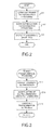
- the primary transformation unit 102 carries out the primary transformation processing ( FIG. 2 : step S1).
- the primary transformation processing will be explained by using FIGs. 3 to 6 .
- rough alignment of the reference shape and target shape is carried out.
- the primary transformation unit 102 reads the reference shape data from the reference shape data storage unit 101, and reads the segment image data from the image data storage unit 103. Then, the primary transformation unit 102 instructs the display unit 112 to display a landmark setting screen that includes the reference shape data and segment image data. The display unit 112 displays the landmark setting screen on the display device in response to the instruction from the primary transformation unit 102 ( FIG. 3 : step S11).
- the user watches the landmark setting screen that is displayed on the display device and carries out rough alignment of the reference shape and the target shape. More specifically, (1) the user sets source landmarks at predetermined positions in the reference shape. (2) The user then sets target landmarks at positions in the target shape, which correspond to the positions where the source landmarks are arranged.
- the predetermined positions are characteristic positions of the heart, for example, the four annular valves, apex, bottom section of the right ventricle fluid surface, myocardial boundary (for example, the boundary between the right ventricle and left ventricle), the end surfaces of the four pulmonary veins, and the inferior vena cava.
- the primary transformation unit 102 then accepts settings for the source landmarks and target landmarks, and stores the data for the source landmarks and the target landmarks (for example, 3-dimensional coordinates) in the first landmark data storage unit 105 (step S13).
- the primary transformation unit 102 carries out a processing, using a method such as the Thin Plate Spline (TPS) Warp method, which will be described later, to transform the reference shape according to the landmark data stored in the first landmark data storage unit 105 (step S15) .
- the primary transformation unit 102 then stores the processing results, which are data of the shape after the primary transformation, in the primary transformation data storage unit 104. The processing then returns to the calling-source processing.
- TPS Thin Plate Spline
- the format of the data stored in the primary transformation data storage unit 104 is the same as the format of the data that is stored in the reference shape data storage unit 101. Moreover, the source landmarks that were used in the primary transformation processing are handled as fixed points in the secondary transformation processing. In other words, the source landmarks that were used in the primary transformation processing do not move in the secondary transformation processing, and the positions are kept the same.
- TPS Warp the TPS Warp method will be explained.
- the transformation is carried out so that the source landmarks lay on the corresponding target landmarks.
- TPS Warp refers to Fred L. Bookstein "Principal Warps: Thin-Plate Splines and the Decomposition of Deformation", IEEE TRANSACTIONS ON PATTERN ANALYSIS AND MACHINE INTELLIGENCE. VOL. 11 NO. 6, PP. 567-585, JUNE 1989 , for example.
- FIG. 5 illustrates an example of applying the primary transformation processing described above to the left ventricle.
- FIG. 5 illustrates the segment images, the target shape that is identified from the segment images, reference shape, and the shape after the primary transformation, which was generated by the primary transformation processing.
- the points attached to the reference shape are the source landmarks
- the points attached to the target shape are the target landmarks.
- FIG. 6 illustrates an example of applying the primary transformation processing described above to the right ventricle.
- FIG. 6 illustrates the segment images, the target shape identified from the segment images, the reference shape, and the shape after the primary transformation, which is generated by the primary transformation processing.
- the points that are attached to the reference shape are the source landmarks, and the points that are attached to the target shape are the target landmarks.
- the shape after the primary transformation is illustrated by meshed lines 60, so that it is easy to compare with the target shape which is depicted within the shape after the transformation.
- the secondary transformation unit 107 carries out a secondary transformation processing (step S3).
- the secondary transformation processing will be explained using FIGs. 7 to 16 .
- the transformation processing when considering that typically the heart has a rounded shape, setting the target landmarks on the normal lines of the source landmarks is thought to be effective.
- the transformation processing based on the TPS Warp method is carried out by placing the source landmarks on the shape before the transformation (i.e. shape after the primary transformation), and placing the target landmarks at the intersecting points between normal lines of the source landmarks and the target shape.
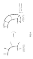
- the normal lines cross as illustrated in FIG. 7
- an unnatural portion that differs from the target shape may occur in the shape after the transformation.
- the target landmarks are placed at points that internally divide the line segments that connect the source landmarks, which are placed on the shape before the transformation (i.e. shape after the primary transformation), with the aforementioned intersecting points, and then the transformation processing is carried out according to the TPS Warp method. Furthermore, by repeating such a transformation processing, the shape gradually approaches the target shape. In this way, an unnatural portion dose not easily occur in the shape after the transformation, and it becomes easier that the direction of the normal lines faces toward the portion that should be originally target.
- m is a variable for counting the number of vertices that were processed.
- the landmark setting processing will be explained using FIGs. 10 to 16 .
- the setting unit 108 of the landmark processing unit 106 identifies one vertex "v" at random from the data after the primary transformation, which is stored in the primary transformation data storage unit 104 ( FIG. 10 : step S41). Then, the setting unit 108 uses the data of the source landmarks (in other words fixed points) that are stored in the first landmark data storage unit 105 and the data of the source landmarks that are stored in the second landmark data storage unit 110 to calculate the Euclidean distances between the vertex "v" and the respective source landmarks. Initially, the second landmark data storage unit 110 stores no data. Therefore, the source landmarks stored in the first landmark data storage unit 105 are used to calculate the distance.
- the setting unit 108 determines whether or not the minimum distance of the Euclidean distances between the vertex "v" and the respective source landmarks is equal to or less than a threshold value D (step S43).
- the step S43 is a processing that is carried out for uniformly placing the vertex "v" on the shape before the secondary transformation processing. In other words, when the distances with other source landmarks are equal to or less than the threshold D, no new source landmarks are added.
- a following equation is satisfied is determined.
- d(v,v i ) indicates the Euclidean distance between the point "v” and the point "v i ".
- the point "v i " is a fixed point (or in other words, is a vertex whose data is stored in the first landmark data storage unit 105 as a source landmark), or is a source landmark (a vertex whose data is stored in the second landmark data storage unit 110).
- step S43 YES route
- the processing returns to the calling-source processing.
- step S43: NO route the setting unit 108 instructs the boundary point search unit 109 to carry out a boundary point search processing.
- the boundary point search unit 109 carries out the boundary point search processing (step S45).
- the boundary point search processing will be explained using FIGs. 11 to 16 .
- the boundary point search unit 109 calculates the unit normal vector n (v) ( FIG. 11 : step S61).
- n (v) is the normal unit vector with respect to the surface H at the vertex v ( ⁇ H).
- the unit normal vector is a normal vector with the length "1".
- H (cV) is a shape surface that is specified by data stored in the primary transformation data storage unit 104
- V ( ⁇ R 3 ) is a voxel space that is specified by the segment images.
- R 3 represents a real number space.
- the pixel value of the segment image data is presumed to be one of the two values 0 or 1.
- the pixel value of the segment image data may be a value other than 0 or 1, or may be a value of two values or more.
- a voxel is an element of a lattice image in the 3-dimensionial image data, which corresponds to a pixel that is an element of a rectangular image in the 2-dimensional image data.
- the boundary point search unit 109 also determines whether or not the vertex "v" exists inside a target shape (step S63). At the step S63, it is determined whether or not the following equation is satisfied. f v > 0
- mapping from the voxel space V to the real number space R (f: V->R) is defined as follows.
- f the elements of the segment image data, which are included in the voxel space V, are correlated with the real number space R.
- f p I
- I is the brightness value of a voxel that includes a point p ( ⁇ v).
- the processing at the step S63 will be explained using FIGs. 12 and 13 .
- the vertex "v" is located on the inside of the target shape. Therefore, by setting a coefficient k in the processing at step S75, which will be described later, so as to be incremented by "1" at a time, the boundary point is searched for in the direction going toward the outside from the inside of the target shape.
- a coefficient k in the processing at step S75 which will be described later
- a search point a point for which a determination will be made as to whether or not the point is a boundary point as described below.
- the boundary point search unit 109 determines whether or not the search point exists inside the voxel space specified by the tomographic image data (step S69). At the step S69, it is determined whether or not the following equation is satisfied. v + kn v ⁇ V
- step S69 NO route
- the processing returns to the calling-source processing. This is because the search point has reached outside the voxel space, so it is possible to determine that the normal line for the vertex "v" does not cross the target shape.
- the boundary point search unit 109 determines whether or not the search point passed through the shape before the transformation (step S71) . At the step S71, it is determined whether or not the following equation is satisfied.
- mapping g V->R 3 is defined as follows. This mapping g correlates the elements of the segment image data that is included in the voxel space V with the real number space R 3 .
- g p ⁇ n p ⁇ if p ⁇ H 0 if p ⁇ H
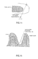
- the processing of the step S71 will be explained using FIGs. 14 and 15 .
- the case where the search point passes through the shape before the transformation before reaching the boundary point may be the case illustrated in FIG. 14 or the case illustrated in FIG. 15 .
- the boundary point does not exist in the search direction according to the extent of the transformation of the target shape with respect to the shape before the transformation.
- there is a possibility that the boundary point is not detected, or that the boundary point is detected at a location that is not suitable.
- the inner product of the normal vector for the vertex "v" and the normal vector for the search point is calculated, and when the inner product is less than 0 (in other words, when the angle between normal vectors is greater than 90 degrees), the search point is determined to have passed through the shape before the transformation.
- step S71 when it is determined that the search point passed through the shape before the transformation (step S71: YES route), it is not possible to detect a suitable boundary point, so the processing returns to the calling-source processing.
- step S71: NO route when it is determined that the search point does not pass through the shape before the transformation (step S71: NO route), the boundary point search unit 109 compares the brightness value in the voxel space, which corresponds to the search point, with the brightness value in the voxel space, which corresponds to the vertex "v”, and determines whether or not the brightness value has changed meaningfully (step S73). At the step S73, it is determined whether or not the following equation is satisfied. f v ⁇ f ⁇ v + kn v
- step S73 NO route
- step S73 when it is determined that the brightness value has changed meaningfully (step S73 : YES route), the boundary point search unit 109 sets the search point as a boundary point (step S77) .
- data for the search point for example, the value of k
- a memory device such as a main memory.
- step S63 the processing that is carried out at the step S63 when it is determined that the vertex "v" is located on the outside of the target shape (step S63: NO route) will be explained.
- the processing in this case differs only in the direction of the search, so the contents of the basic processing is as described above.
- the processing of the step S79 is the same as the processing of the step S65
- the processing of the step S81 is the same as the processing of the step S67
- the processing of the step S83 is the same as the processing of the step S69
- the processing of the step S85 is the same as the processing of the step S71
- the processing of the step S87 is the same as the processing of the step S73. Therefore, detailed explanations of the processing from step S79 to step S87 are omitted.
- the search point is moved one voxel at a time in the normal direction from the outside of the target shape toward the inside.
- theprocessingof the step S91 is the same as the processing of the step S77.
- the setting unit 108 determines whether or not a boundary point was detected by the boundary point search unit 109 (step S47). When it is determined that a boundary point was not detected (step S47: NO route), the processing returns to the calling-source processing in order to carry out a processing for the next vertex.
- step S47 YES route
- the setting unit 108 sets an internal dividing point on the line segment that connects the vertex "v” and the boundary point "v+kn (v)"asatargetlandmark (stepS49) . More specifically, a point as described below is set as the target landmark. v + t T ⁇ kn v
- the setting unit 108 sets the vertex "v" as a source landmark (step S51).
- the setting unit 108 stores the data for the set source landmark and the target landmark in the second landmark data storage unit 110. Then, the processing returns to the calling-source processing.
- the secondary transformation unit 107 determines whether or not m ⁇ N is satisfied for the variable m (step S29).
- N is the total number of vertices in the shape after the primary transformation (or the shape after transforming the shape after the primary transformation).
- the secondarytransformationunit 107 carries out the transformation based on the TPS Warp according to the data for the source landmarks and target landmarks that are stored in the second landmark data storage unit 110, and stores the data for the transformed shape in the primary transformation data storage unit 104 (step S31).
- a point that was a source landmark in the primary transformation processing is handled as a fixed point and is not moved.
- the secondary transformation unit 107 determines whether t ⁇ T is satisfied for variable t (step S33). When it is determined that t ⁇ T is satisfied (step S33: YES route), the processing returns to the processing of the step S23 in order to carry out further transformation processing.
- step S33 NO route
- the transformation has been carried out T times, so the secondary transformation unit 107 stores the data for the shape after the secondary transformation processing in the secondary transformation data storage unit 111, and the processing returns to the calling-source processing.
- the shape after the primary transformation approaches the target shape, and it becomes possible to obtain 3-dimensional shape data having high precision. Moreover, with such a kind of transformation method, the processing time becomes comparatively short.
- the display unit 112 displays the data stored in the secondary transformation data storage unit 111 on the display device or the like (step S5). The processing then ends.
- FIG. 17 illustrates an example of data that is displayed on the display device.
- the target shape and the shape after the secondary transformation which is indicated by mesh lines, are displayed.
- the figure on the left side is a figure illustrating the entire transformed portion, and the figure on the right side is an enlarged view of part of the transformed portion.
- the reference shape of the heart is transformed so as to approach the target shape that is specified by the segment image data, and it is possible to obtain highly precise 3-dimensional data.
- the order of steps may be changed as long as the processing results do not change. Furthermore, as long as the processing results do not change, the steps may be executed in parallel.
- the segment image data is displayed on the landmark setting screen to set the target landmarks.
- tomographic images such as CT images may be displayed to set the target landmarks.
- the processing such as described above is not only applicable to the heart, but can also be applied to other objects.
- the aforementioned shape data generation apparatus 1 is computer device as shown in FIG. 18 . That is, a memory 2501 (storage device), a CPU 2503 (processor), a hard disk drive (HDD) 2505, a display controller 2507 connected to a display device 2509, a drive device 2513 for a removable disk 2511, an input device 2515, and a communication controller 2517 for connection with a network are connected through a bus 2519 as shown in FIG. 18 .
- An operating system (OS) and an application program for carrying out the foregoing processing in the embodiment, are stored in the HDD 2505, and when executed by the CPU 2503, they are read out from the HDD 2505 to the memory 2501.
- OS operating system
- an application program for carrying out the foregoing processing in the embodiment are stored in the HDD 2505, and when executed by the CPU 2503, they are read out from the HDD 2505 to the memory 2501.
- the CPU 2503 controls the display controller 2507, the communication controller 2517, and the drive device 2513, and causes them to perform necessary operations. Besides, intermediate processing data is stored in the memory 2501, and if necessary, it is stored in the HDD 2505.
- the application program to realize the aforementioned functions is stored in the computer-readable, non-transitory removable disk 2511 and distributed, and then it is installed into the HDD 2505 from the drive device 2513. It may be installed into the HDD 2505 via the network such as the Internet and the communication controller 2517.
- the hardware such as the CPU 2503 and the memory 2501, the OS and the necessary application programs systematically cooperate with each other, so that various functions as described above in details are realized.
- the respective processing units illustrated in FIG. 1 may be realized by combinations of the CPU 2503 and program, in other words, by executing, by the CPU 2503, the program. More specifically, the CPU 2503 carries out operations according to the program stored in the HDD 2505 or memory 2501 to function as the aforementionedprocessingunits . Moreover, the respective data storage units illustrated in FIG. 1 may be realized by the memory 2501 or HDD 2505 in FIG. 18 .
- a shape data generation method relating to this embodiment includes (A) identifying one orplural first vertices satisfying a predetermined condition including a certain condition, from among vertices of a first shape to be transformed, wherein data concerning the vertices of the first shape is stored in a shape data storage unit, and the certain condition is a condition that a normal line of a vertex to be processed crosses with a second shape identified by tomographic image data stored in an image data storage unit; (B) transforming the first shape so as to move each of the one or plural vertices toward a corresponding normal direction of the identified first vertex a predetermined distance, and storing data concerning the vertices of the first shape after the transforming into the shape data storage unit; and (C) storing data concerning the vertices of the first shape transformed by executing the identifying and the transforming the predetermined number of times, into an output data storage unit.
- the aforementioned predetermined condition may include a condition the vertex to be processed is far from any one of the one or plural first vertices a second predetermined distance or more.
- the aforementioned method may further include: (D) displaying data stored in a reference shape data storage unit storing data of vertices of a reference shape of an object relating to the first shape and the second shape, and data of the second shape, and accepting designation of a start position in the reference shape and designation of a target point corresponding to the start point in the second shape; and (E) generating the first shape by transforming the reference shape so as to place the start point on the target point, and storing data concerning vertices of the reference shape after the transformation into the shape data storage unit.
- the predetermined condition described above may include a condition that the vertex to be processed is not the start point, and the transforming is carried out not so as to move the start point.
- the aforementioned identifying may include (a1) moving the vertex to be processed to a normal direction of the vertex to be processed a predetermined third distance; (a2) determining whether or not a moving destination point is included in a voxel space identified from the image data; (a3) upon determining that the moving destination point is included in the voxel space, determining based on an inner product of a normal vector of the vertex to be processed and a normal vector of the moving destination point, whether or not the moving destination point passes through the first shape; (a4) upon determining that the moving destination vertex does not pass through the first shape, comparing a brightness value at the moving destination point with a brightness value at the vertex to be processed to determine whether or not the brightness value changes; (a5) upon determining that the brightness value changes, determining that the condition that the normal line of the vertex to be processed crosses with the second shape is satisfied; (a6) upon determining that the moving destination point is not included in the voxel space or upon determining that the moving destination point is
- an object relating to the first shape and the second shape may be a heart, and a portion to which the start point and the target point are designated may be at least one of annular valves, an apex, a bottom section of a right ventricle fluid surface, a myocardial boundary, a pulmonary vein, and an inferior vena cava of the heart.
- a program causing a computer to execute the aforementioned processing, and such a program is stored in a computer readable storage medium or storage device such as a flexible disk, CD-ROM, DVD-ROM, magneto-optic disk, a semiconductor memory, and hard disk.
- a computer readable storage medium or storage device such as a flexible disk, CD-ROM, DVD-ROM, magneto-optic disk, a semiconductor memory, and hard disk.
- the intermediate processing result is temporarily stored in a storage device such as a main memory or the like.
Landscapes
- Engineering & Computer Science (AREA)
- Architecture (AREA)
- Computer Graphics (AREA)
- Computer Hardware Design (AREA)
- General Engineering & Computer Science (AREA)
- Software Systems (AREA)
- Physics & Mathematics (AREA)
- General Physics & Mathematics (AREA)
- Theoretical Computer Science (AREA)
- Apparatus For Radiation Diagnosis (AREA)
- Image Generation (AREA)
- Processing Or Creating Images (AREA)
- Image Processing (AREA)
Applications Claiming Priority (1)
| Application Number | Priority Date | Filing Date | Title |
|---|---|---|---|
| JP2011147078A JP5721225B2 (ja) | 2011-07-01 | 2011-07-01 | 形状データ生成方法、プログラム及び装置 |
Publications (3)
| Publication Number | Publication Date |
|---|---|
| EP2541501A2 true EP2541501A2 (fr) | 2013-01-02 |
| EP2541501A3 EP2541501A3 (fr) | 2017-06-21 |
| EP2541501B1 EP2541501B1 (fr) | 2023-07-26 |
Family
ID=46458146
Family Applications (1)
| Application Number | Title | Priority Date | Filing Date |
|---|---|---|---|
| EP12170176.7A Active EP2541501B1 (fr) | 2011-07-01 | 2012-05-31 | Dispositif et méthode pour générer de données de forme |
Country Status (3)
| Country | Link |
|---|---|
| US (1) | US9208617B2 (fr) |
| EP (1) | EP2541501B1 (fr) |
| JP (1) | JP5721225B2 (fr) |
Families Citing this family (6)
| Publication number | Priority date | Publication date | Assignee | Title |
|---|---|---|---|---|
| US9818200B2 (en) | 2013-11-14 | 2017-11-14 | Toshiba Medical Systems Corporation | Apparatus and method for multi-atlas based segmentation of medical image data |
| US9193868B1 (en) | 2014-05-06 | 2015-11-24 | Sabic Global Technologies B.V. | Article comprising poly(phenylene ether)-polysiloxane copolymer composition |
| JP6346850B2 (ja) | 2014-11-18 | 2018-06-20 | 富士通株式会社 | モデリング装置、モデリング方法、及びモデリングプログラム |
| WO2016174534A1 (fr) | 2015-04-27 | 2016-11-03 | Sabic Global Technologies B.V. | Composition et article de poly(éther de phénylène) |
| EP3866107A1 (fr) * | 2020-02-14 | 2021-08-18 | Koninklijke Philips N.V. | Segmentation d'image basée sur un modèle |
| CN112509131B (zh) * | 2020-11-20 | 2022-12-06 | 上海莉莉丝网络科技有限公司 | 游戏地图内地图区域边界的渲染方法、系统及计算机可读存储介质 |
Family Cites Families (13)
| Publication number | Priority date | Publication date | Assignee | Title |
|---|---|---|---|---|
| US5444838A (en) * | 1991-03-18 | 1995-08-22 | Hewlett-Packard Company | Computer system and method for interference checking of polyhedra using capping polygons |
| WO2002073536A2 (fr) | 2001-03-09 | 2002-09-19 | Koninklijke Philips Electronics N.V. | Segmentation d'image |
| DE10111661A1 (de) | 2001-03-09 | 2002-09-12 | Philips Corp Intellectual Pty | Verfahren zum Segmentieren einer in einem Objekt enthaltenen dreidimensionalen Struktur, insbesondere für die medizinische Bildanalyse |
| WO2004110309A2 (fr) * | 2003-06-11 | 2004-12-23 | Case Western Reserve University | Conception assistee par ordinateur d'implants du squelette |
| JP5017909B2 (ja) * | 2005-06-22 | 2012-09-05 | コニカミノルタエムジー株式会社 | 領域抽出装置、領域抽出方法及びプログラム |
| JP4969809B2 (ja) * | 2005-07-07 | 2012-07-04 | 株式会社東芝 | 超音波診断装置、画像処理装置及び画像処理方法 |
| JP2007312971A (ja) * | 2006-05-25 | 2007-12-06 | Konica Minolta Medical & Graphic Inc | モデリング装置、モデリング方法及びプログラム |
| US7853058B2 (en) * | 2006-11-22 | 2010-12-14 | Toshiba Medical Visualization Systems Europe, Limited | Determining a viewpoint for navigating a virtual camera through a biological object with a lumen |
| US9050470B2 (en) * | 2008-05-15 | 2015-06-09 | Intelect Medical, Inc. | Clinician programmer system interface for monitoring patient progress |
| JP4931022B2 (ja) | 2008-09-04 | 2012-05-16 | 独立行政法人産業技術総合研究所 | 衣類状態推定方法及びプログラム |
| JP5610129B2 (ja) | 2010-03-26 | 2014-10-22 | 富士通株式会社 | 3次元テンプレート変形方法、装置及びプログラム |
| US8538737B2 (en) * | 2010-09-17 | 2013-09-17 | Adobe Systems Incorporated | Curve editing with physical simulation of mass points and spring forces |
| US8669995B2 (en) * | 2010-10-08 | 2014-03-11 | Adobe Systems Incorporated | Methods and apparatus for stroke grouping for high-level sketch editing |
-
2011
- 2011-07-01 JP JP2011147078A patent/JP5721225B2/ja active Active
-
2012
- 2012-05-30 US US13/483,495 patent/US9208617B2/en active Active
- 2012-05-31 EP EP12170176.7A patent/EP2541501B1/fr active Active
Non-Patent Citations (1)
| Title |
|---|
| FRED L. BOOKSTEIN: "Principal Warps: Thin-Plate Splines and the Decomposition of Deformation", IEEE TRANSACTIONS ON PATTERN ANALYSIS AND MACHINE INTELLIGENCE, vol. 11, no. 6, June 1989 (1989-06-01), pages 567 - 585 |
Also Published As
| Publication number | Publication date |
|---|---|
| EP2541501B1 (fr) | 2023-07-26 |
| US20130002677A1 (en) | 2013-01-03 |
| EP2541501A3 (fr) | 2017-06-21 |
| JP5721225B2 (ja) | 2015-05-20 |
| US9208617B2 (en) | 2015-12-08 |
| JP2013015945A (ja) | 2013-01-24 |
Similar Documents
| Publication | Publication Date | Title |
|---|---|---|
| EP2541501A2 (fr) | Dispositif et programme pour des generation de données de forme | |
| JP4152648B2 (ja) | 対象物に含まれる三次元画像をセグメント化する方法 | |
| US20110262015A1 (en) | Image processing apparatus, image processing method, and storage medium | |
| EP2688040B1 (fr) | Recalage 3D des modèles tridimensionnels en utilisant des point choisis particulièrement | |
| EP2369553A2 (fr) | Procédé et appareil de transformation de modèle tridimensionnel | |
| EP2688041A2 (fr) | Procédé et appareil de traitement d'affichage | |
| US10891787B2 (en) | Apparatus and method for creating biological model | |
| US7773786B2 (en) | Method and apparatus for three-dimensional interactive tools for semi-automatic segmentation and editing of image objects | |
| US9697600B2 (en) | Multi-modal segmentatin of image data | |
| US10762648B2 (en) | Image processing apparatus, image processing method, image processing system, and program | |
| US9836891B2 (en) | Shape data generation method and apparatus | |
| JP6001783B2 (ja) | 神経繊維構造の定位 | |
| CN102388403A (zh) | 用于器官分割的交互式迭代最近点算法 | |
| US9547906B2 (en) | System and method for data driven editing of rib unfolding | |
| US9607423B2 (en) | Shape data generation method and apparatus | |
| EP3259733B1 (fr) | Définition dynamique d'une région d'intérêt pour suivre des fibres nerveuses | |
| CN111226260A (zh) | 分割图像 | |
| US20140032180A1 (en) | Method and apparatus for computing deformation of an object | |
| CN102138159B (zh) | 满足预定义空间关系的对象的基于模型的同步分割 | |
| JP5701208B2 (ja) | 医用画像表示装置及び医用画像表示方法 | |
| JP6757242B2 (ja) | 線維状組織抽出装置、線維状組織抽出方法並びに線維状組織抽出プログラム | |
| US9836837B2 (en) | Method and device for determining a transformation between two images of an anatomical structure | |
| JP6346850B2 (ja) | モデリング装置、モデリング方法、及びモデリングプログラム | |
| WO2017130263A1 (fr) | Appareil de traitement d'images, procédé de traitement d'images, système de traitement d'images, et programme |
Legal Events
| Date | Code | Title | Description |
|---|---|---|---|
| PUAI | Public reference made under article 153(3) epc to a published international application that has entered the european phase |
Free format text: ORIGINAL CODE: 0009012 |
|
| AK | Designated contracting states |
Kind code of ref document: A2 Designated state(s): AL AT BE BG CH CY CZ DE DK EE ES FI FR GB GR HR HU IE IS IT LI LT LU LV MC MK MT NL NO PL PT RO RS SE SI SK SM TR |
|
| AX | Request for extension of the european patent |
Extension state: BA ME |
|
| PUAL | Search report despatched |
Free format text: ORIGINAL CODE: 0009013 |
|
| AK | Designated contracting states |
Kind code of ref document: A3 Designated state(s): AL AT BE BG CH CY CZ DE DK EE ES FI FR GB GR HR HU IE IS IT LI LT LU LV MC MK MT NL NO PL PT RO RS SE SI SK SM TR |
|
| AX | Request for extension of the european patent |
Extension state: BA ME |
|
| RIC1 | Information provided on ipc code assigned before grant |
Ipc: G06T 19/00 20110101AFI20170517BHEP Ipc: G06T 19/20 20110101ALI20170517BHEP |
|
| STAA | Information on the status of an ep patent application or granted ep patent |
Free format text: STATUS: REQUEST FOR EXAMINATION WAS MADE |
|
| 17P | Request for examination filed |
Effective date: 20171013 |
|
| RBV | Designated contracting states (corrected) |
Designated state(s): AL AT BE BG CH CY CZ DE DK EE ES FI FR GB GR HR HU IE IS IT LI LT LU LV MC MK MT NL NO PL PT RO RS SE SI SK SM TR |
|
| STAA | Information on the status of an ep patent application or granted ep patent |
Free format text: STATUS: EXAMINATION IS IN PROGRESS |
|
| 17Q | First examination report despatched |
Effective date: 20180404 |
|
| GRAP | Despatch of communication of intention to grant a patent |
Free format text: ORIGINAL CODE: EPIDOSNIGR1 |
|
| STAA | Information on the status of an ep patent application or granted ep patent |
Free format text: STATUS: GRANT OF PATENT IS INTENDED |
|
| INTG | Intention to grant announced |
Effective date: 20230215 |
|
| GRAS | Grant fee paid |
Free format text: ORIGINAL CODE: EPIDOSNIGR3 |
|
| GRAA | (expected) grant |
Free format text: ORIGINAL CODE: 0009210 |
|
| STAA | Information on the status of an ep patent application or granted ep patent |
Free format text: STATUS: THE PATENT HAS BEEN GRANTED |
|
| AK | Designated contracting states |
Kind code of ref document: B1 Designated state(s): AL AT BE BG CH CY CZ DE DK EE ES FI FR GB GR HR HU IE IS IT LI LT LU LV MC MK MT NL NO PL PT RO RS SE SI SK SM TR |
|
| REG | Reference to a national code |
Ref country code: CH Ref legal event code: EP |
|
| REG | Reference to a national code |
Ref country code: DE Ref legal event code: R096 Ref document number: 602012079878 Country of ref document: DE |
|
| REG | Reference to a national code |
Ref country code: IE Ref legal event code: FG4D |
|
| REG | Reference to a national code |
Ref country code: LT Ref legal event code: MG9D |
|
| REG | Reference to a national code |
Ref country code: NL Ref legal event code: MP Effective date: 20230726 |
|
| REG | Reference to a national code |
Ref country code: AT Ref legal event code: MK05 Ref document number: 1592825 Country of ref document: AT Kind code of ref document: T Effective date: 20230726 |
|
| PG25 | Lapsed in a contracting state [announced via postgrant information from national office to epo] |
Ref country code: NL Free format text: LAPSE BECAUSE OF FAILURE TO SUBMIT A TRANSLATION OF THE DESCRIPTION OR TO PAY THE FEE WITHIN THE PRESCRIBED TIME-LIMIT Effective date: 20230726 |
|
| PG25 | Lapsed in a contracting state [announced via postgrant information from national office to epo] |
Ref country code: GR Free format text: LAPSE BECAUSE OF FAILURE TO SUBMIT A TRANSLATION OF THE DESCRIPTION OR TO PAY THE FEE WITHIN THE PRESCRIBED TIME-LIMIT Effective date: 20231027 |
|
| PG25 | Lapsed in a contracting state [announced via postgrant information from national office to epo] |
Ref country code: IS Free format text: LAPSE BECAUSE OF FAILURE TO SUBMIT A TRANSLATION OF THE DESCRIPTION OR TO PAY THE FEE WITHIN THE PRESCRIBED TIME-LIMIT Effective date: 20231126 |
|
| PG25 | Lapsed in a contracting state [announced via postgrant information from national office to epo] |
Ref country code: SE Free format text: LAPSE BECAUSE OF FAILURE TO SUBMIT A TRANSLATION OF THE DESCRIPTION OR TO PAY THE FEE WITHIN THE PRESCRIBED TIME-LIMIT Effective date: 20230726 Ref country code: RS Free format text: LAPSE BECAUSE OF FAILURE TO SUBMIT A TRANSLATION OF THE DESCRIPTION OR TO PAY THE FEE WITHIN THE PRESCRIBED TIME-LIMIT Effective date: 20230726 Ref country code: PT Free format text: LAPSE BECAUSE OF FAILURE TO SUBMIT A TRANSLATION OF THE DESCRIPTION OR TO PAY THE FEE WITHIN THE PRESCRIBED TIME-LIMIT Effective date: 20231127 Ref country code: NO Free format text: LAPSE BECAUSE OF FAILURE TO SUBMIT A TRANSLATION OF THE DESCRIPTION OR TO PAY THE FEE WITHIN THE PRESCRIBED TIME-LIMIT Effective date: 20231026 Ref country code: LV Free format text: LAPSE BECAUSE OF FAILURE TO SUBMIT A TRANSLATION OF THE DESCRIPTION OR TO PAY THE FEE WITHIN THE PRESCRIBED TIME-LIMIT Effective date: 20230726 Ref country code: LT Free format text: LAPSE BECAUSE OF FAILURE TO SUBMIT A TRANSLATION OF THE DESCRIPTION OR TO PAY THE FEE WITHIN THE PRESCRIBED TIME-LIMIT Effective date: 20230726 Ref country code: IS Free format text: LAPSE BECAUSE OF FAILURE TO SUBMIT A TRANSLATION OF THE DESCRIPTION OR TO PAY THE FEE WITHIN THE PRESCRIBED TIME-LIMIT Effective date: 20231126 Ref country code: HR Free format text: LAPSE BECAUSE OF FAILURE TO SUBMIT A TRANSLATION OF THE DESCRIPTION OR TO PAY THE FEE WITHIN THE PRESCRIBED TIME-LIMIT Effective date: 20230726 Ref country code: GR Free format text: LAPSE BECAUSE OF FAILURE TO SUBMIT A TRANSLATION OF THE DESCRIPTION OR TO PAY THE FEE WITHIN THE PRESCRIBED TIME-LIMIT Effective date: 20231027 Ref country code: FI Free format text: LAPSE BECAUSE OF FAILURE TO SUBMIT A TRANSLATION OF THE DESCRIPTION OR TO PAY THE FEE WITHIN THE PRESCRIBED TIME-LIMIT Effective date: 20230726 Ref country code: AT Free format text: LAPSE BECAUSE OF FAILURE TO SUBMIT A TRANSLATION OF THE DESCRIPTION OR TO PAY THE FEE WITHIN THE PRESCRIBED TIME-LIMIT Effective date: 20230726 |
|
| PG25 | Lapsed in a contracting state [announced via postgrant information from national office to epo] |
Ref country code: PL Free format text: LAPSE BECAUSE OF FAILURE TO SUBMIT A TRANSLATION OF THE DESCRIPTION OR TO PAY THE FEE WITHIN THE PRESCRIBED TIME-LIMIT Effective date: 20230726 |
|
| PG25 | Lapsed in a contracting state [announced via postgrant information from national office to epo] |
Ref country code: ES Free format text: LAPSE BECAUSE OF FAILURE TO SUBMIT A TRANSLATION OF THE DESCRIPTION OR TO PAY THE FEE WITHIN THE PRESCRIBED TIME-LIMIT Effective date: 20230726 |
|
| REG | Reference to a national code |
Ref country code: DE Ref legal event code: R097 Ref document number: 602012079878 Country of ref document: DE |
|
| PG25 | Lapsed in a contracting state [announced via postgrant information from national office to epo] |
Ref country code: SM Free format text: LAPSE BECAUSE OF FAILURE TO SUBMIT A TRANSLATION OF THE DESCRIPTION OR TO PAY THE FEE WITHIN THE PRESCRIBED TIME-LIMIT Effective date: 20230726 Ref country code: RO Free format text: LAPSE BECAUSE OF FAILURE TO SUBMIT A TRANSLATION OF THE DESCRIPTION OR TO PAY THE FEE WITHIN THE PRESCRIBED TIME-LIMIT Effective date: 20230726 Ref country code: ES Free format text: LAPSE BECAUSE OF FAILURE TO SUBMIT A TRANSLATION OF THE DESCRIPTION OR TO PAY THE FEE WITHIN THE PRESCRIBED TIME-LIMIT Effective date: 20230726 Ref country code: EE Free format text: LAPSE BECAUSE OF FAILURE TO SUBMIT A TRANSLATION OF THE DESCRIPTION OR TO PAY THE FEE WITHIN THE PRESCRIBED TIME-LIMIT Effective date: 20230726 Ref country code: DK Free format text: LAPSE BECAUSE OF FAILURE TO SUBMIT A TRANSLATION OF THE DESCRIPTION OR TO PAY THE FEE WITHIN THE PRESCRIBED TIME-LIMIT Effective date: 20230726 Ref country code: CZ Free format text: LAPSE BECAUSE OF FAILURE TO SUBMIT A TRANSLATION OF THE DESCRIPTION OR TO PAY THE FEE WITHIN THE PRESCRIBED TIME-LIMIT Effective date: 20230726 Ref country code: SK Free format text: LAPSE BECAUSE OF FAILURE TO SUBMIT A TRANSLATION OF THE DESCRIPTION OR TO PAY THE FEE WITHIN THE PRESCRIBED TIME-LIMIT Effective date: 20230726 |
|
| PG25 | Lapsed in a contracting state [announced via postgrant information from national office to epo] |
Ref country code: IT Free format text: LAPSE BECAUSE OF FAILURE TO SUBMIT A TRANSLATION OF THE DESCRIPTION OR TO PAY THE FEE WITHIN THE PRESCRIBED TIME-LIMIT Effective date: 20230726 |
|
| PLBE | No opposition filed within time limit |
Free format text: ORIGINAL CODE: 0009261 |
|
| STAA | Information on the status of an ep patent application or granted ep patent |
Free format text: STATUS: NO OPPOSITION FILED WITHIN TIME LIMIT |
|
| 26N | No opposition filed |
Effective date: 20240429 |
|
| PG25 | Lapsed in a contracting state [announced via postgrant information from national office to epo] |
Ref country code: SI Free format text: LAPSE BECAUSE OF FAILURE TO SUBMIT A TRANSLATION OF THE DESCRIPTION OR TO PAY THE FEE WITHIN THE PRESCRIBED TIME-LIMIT Effective date: 20230726 |
|
| PG25 | Lapsed in a contracting state [announced via postgrant information from national office to epo] |
Ref country code: BG Free format text: LAPSE BECAUSE OF FAILURE TO SUBMIT A TRANSLATION OF THE DESCRIPTION OR TO PAY THE FEE WITHIN THE PRESCRIBED TIME-LIMIT Effective date: 20230726 |
|
| PG25 | Lapsed in a contracting state [announced via postgrant information from national office to epo] |
Ref country code: BG Free format text: LAPSE BECAUSE OF FAILURE TO SUBMIT A TRANSLATION OF THE DESCRIPTION OR TO PAY THE FEE WITHIN THE PRESCRIBED TIME-LIMIT Effective date: 20230726 |
|
| REG | Reference to a national code |
Ref country code: CH Ref legal event code: PL |
|
| PG25 | Lapsed in a contracting state [announced via postgrant information from national office to epo] |
Ref country code: MC Free format text: LAPSE BECAUSE OF FAILURE TO SUBMIT A TRANSLATION OF THE DESCRIPTION OR TO PAY THE FEE WITHIN THE PRESCRIBED TIME-LIMIT Effective date: 20230726 |
|
| PG25 | Lapsed in a contracting state [announced via postgrant information from national office to epo] |
Ref country code: LU Free format text: LAPSE BECAUSE OF NON-PAYMENT OF DUE FEES Effective date: 20240531 |
|
| PG25 | Lapsed in a contracting state [announced via postgrant information from national office to epo] |
Ref country code: MC Free format text: LAPSE BECAUSE OF FAILURE TO SUBMIT A TRANSLATION OF THE DESCRIPTION OR TO PAY THE FEE WITHIN THE PRESCRIBED TIME-LIMIT Effective date: 20230726 Ref country code: LU Free format text: LAPSE BECAUSE OF NON-PAYMENT OF DUE FEES Effective date: 20240531 Ref country code: CH Free format text: LAPSE BECAUSE OF NON-PAYMENT OF DUE FEES Effective date: 20240531 |
|
| REG | Reference to a national code |
Ref country code: BE Ref legal event code: MM Effective date: 20240531 |
|
| PG25 | Lapsed in a contracting state [announced via postgrant information from national office to epo] |
Ref country code: IE Free format text: LAPSE BECAUSE OF NON-PAYMENT OF DUE FEES Effective date: 20240531 |
|
| PG25 | Lapsed in a contracting state [announced via postgrant information from national office to epo] |
Ref country code: BE Free format text: LAPSE BECAUSE OF NON-PAYMENT OF DUE FEES Effective date: 20240531 |
|
| PGFP | Annual fee paid to national office [announced via postgrant information from national office to epo] |
Ref country code: DE Payment date: 20250423 Year of fee payment: 14 |
|
| PGFP | Annual fee paid to national office [announced via postgrant information from national office to epo] |
Ref country code: GB Payment date: 20250423 Year of fee payment: 14 |
|
| PGFP | Annual fee paid to national office [announced via postgrant information from national office to epo] |
Ref country code: FR Payment date: 20250423 Year of fee payment: 14 |
|
| PG25 | Lapsed in a contracting state [announced via postgrant information from national office to epo] |
Ref country code: CY Free format text: LAPSE BECAUSE OF FAILURE TO SUBMIT A TRANSLATION OF THE DESCRIPTION OR TO PAY THE FEE WITHIN THE PRESCRIBED TIME-LIMIT; INVALID AB INITIO Effective date: 20120531 |
|
| PG25 | Lapsed in a contracting state [announced via postgrant information from national office to epo] |
Ref country code: HU Free format text: LAPSE BECAUSE OF FAILURE TO SUBMIT A TRANSLATION OF THE DESCRIPTION OR TO PAY THE FEE WITHIN THE PRESCRIBED TIME-LIMIT; INVALID AB INITIO Effective date: 20120531 |