EP2541667A1 - Système de batterie secondaire - Google Patents
Système de batterie secondaire Download PDFInfo
- Publication number
- EP2541667A1 EP2541667A1 EP12174267A EP12174267A EP2541667A1 EP 2541667 A1 EP2541667 A1 EP 2541667A1 EP 12174267 A EP12174267 A EP 12174267A EP 12174267 A EP12174267 A EP 12174267A EP 2541667 A1 EP2541667 A1 EP 2541667A1
- Authority
- EP
- European Patent Office
- Prior art keywords
- battery
- resistance
- charge
- lithium ion
- standard
- Prior art date
- Legal status (The legal status is an assumption and is not a legal conclusion. Google has not performed a legal analysis and makes no representation as to the accuracy of the status listed.)
- Granted
Links
Images

Classifications
-
- H—ELECTRICITY
- H01—ELECTRIC ELEMENTS
- H01M—PROCESSES OR MEANS, e.g. BATTERIES, FOR THE DIRECT CONVERSION OF CHEMICAL ENERGY INTO ELECTRICAL ENERGY
- H01M10/00—Secondary cells; Manufacture thereof
- H01M10/42—Methods or arrangements for servicing or maintenance of secondary cells or secondary half-cells
- H01M10/425—Structural combination with electronic components, e.g. electronic circuits integrated to the outside of the casing
-
- H—ELECTRICITY
- H01—ELECTRIC ELEMENTS
- H01M—PROCESSES OR MEANS, e.g. BATTERIES, FOR THE DIRECT CONVERSION OF CHEMICAL ENERGY INTO ELECTRICAL ENERGY
- H01M10/00—Secondary cells; Manufacture thereof
- H01M10/42—Methods or arrangements for servicing or maintenance of secondary cells or secondary half-cells
- H01M10/425—Structural combination with electronic components, e.g. electronic circuits integrated to the outside of the casing
- H01M10/4257—Smart batteries, e.g. electronic circuits inside the housing of the cells or batteries
-
- H—ELECTRICITY
- H01—ELECTRIC ELEMENTS
- H01M—PROCESSES OR MEANS, e.g. BATTERIES, FOR THE DIRECT CONVERSION OF CHEMICAL ENERGY INTO ELECTRICAL ENERGY
- H01M10/00—Secondary cells; Manufacture thereof
- H01M10/42—Methods or arrangements for servicing or maintenance of secondary cells or secondary half-cells
- H01M10/44—Methods for charging or discharging
-
- H—ELECTRICITY
- H01—ELECTRIC ELEMENTS
- H01M—PROCESSES OR MEANS, e.g. BATTERIES, FOR THE DIRECT CONVERSION OF CHEMICAL ENERGY INTO ELECTRICAL ENERGY
- H01M10/00—Secondary cells; Manufacture thereof
- H01M10/42—Methods or arrangements for servicing or maintenance of secondary cells or secondary half-cells
- H01M10/44—Methods for charging or discharging
- H01M10/443—Methods for charging or discharging in response to temperature
-
- H—ELECTRICITY
- H01—ELECTRIC ELEMENTS
- H01M—PROCESSES OR MEANS, e.g. BATTERIES, FOR THE DIRECT CONVERSION OF CHEMICAL ENERGY INTO ELECTRICAL ENERGY
- H01M10/00—Secondary cells; Manufacture thereof
- H01M10/42—Methods or arrangements for servicing or maintenance of secondary cells or secondary half-cells
- H01M10/48—Accumulators combined with arrangements for measuring, testing or indicating the condition of cells, e.g. the level or density of the electrolyte
-
- H—ELECTRICITY
- H01—ELECTRIC ELEMENTS
- H01M—PROCESSES OR MEANS, e.g. BATTERIES, FOR THE DIRECT CONVERSION OF CHEMICAL ENERGY INTO ELECTRICAL ENERGY
- H01M10/00—Secondary cells; Manufacture thereof
- H01M10/42—Methods or arrangements for servicing or maintenance of secondary cells or secondary half-cells
- H01M10/48—Accumulators combined with arrangements for measuring, testing or indicating the condition of cells, e.g. the level or density of the electrolyte
- H01M10/486—Accumulators combined with arrangements for measuring, testing or indicating the condition of cells, e.g. the level or density of the electrolyte for measuring temperature
-
- H—ELECTRICITY
- H02—GENERATION; CONVERSION OR DISTRIBUTION OF ELECTRIC POWER
- H02J—ELECTRIC POWER NETWORKS; CIRCUIT ARRANGEMENTS OR SYSTEMS FOR SUPPLYING OR DISTRIBUTING ELECTRIC POWER; SYSTEMS FOR STORING ELECTRIC ENERGY
- H02J7/00—Circuit arrangements for charging or discharging batteries or for supplying loads from batteries
-
- Y—GENERAL TAGGING OF NEW TECHNOLOGICAL DEVELOPMENTS; GENERAL TAGGING OF CROSS-SECTIONAL TECHNOLOGIES SPANNING OVER SEVERAL SECTIONS OF THE IPC; TECHNICAL SUBJECTS COVERED BY FORMER USPC CROSS-REFERENCE ART COLLECTIONS [XRACs] AND DIGESTS
- Y02—TECHNOLOGIES OR APPLICATIONS FOR MITIGATION OR ADAPTATION AGAINST CLIMATE CHANGE
- Y02E—REDUCTION OF GREENHOUSE GAS [GHG] EMISSIONS, RELATED TO ENERGY GENERATION, TRANSMISSION OR DISTRIBUTION
- Y02E60/00—Enabling technologies; Technologies with a potential or indirect contribution to GHG emissions mitigation
- Y02E60/10—Energy storage using batteries
Definitions
- the present invention relates to a battery system using non-aqueous secondary batteries typically represented by lithium ion batteries, a battery device having the battery system mounted thereon, and a battery system-mounted vehicle.
- lithium ion batteries have been utilized as a driving power supply for vehicles such as hybrid cars and electric cars and portable electronic devices such as notebook personal computers and digital cameras.
- Degradation phenomena occur in such a battery system using lithium ion batteries. Due to repeated charge-discharge cycles, the battery capacity is lowered and the direct current resistance of the battery is increased, resulting in degradation phenomena. The degradation phenomena likely occur in charge-discharge cycles under the condition of large current and large capacity. For example, the degradation phenomena means that the capacity of insertable lithium ions to positive or negative electrode materials decreases and thereby battery performance lowers. Therefore, charging or discharging to a lithium ion battery is controlled such that the state of charge (SOC) of the battery falls within a predetermined range.
- SOC state of charge
- 4052080 discloses a control device that judges the state as overcharge when the voltage of a lithium ion battery exceeds a maximum allowable voltage and judges the state as over-discharge when the voltage is lower than the minimum allowable voltage, thereby stopping charging or discharging.
- the battery direct current resistance increases when the lithium ion battery is at a low temperature or in a low SOC.
- the voltage may instantaneously exceed the maximum allowable voltage greatly due to over voltage during charging, whereas the voltage may be greatly made lower than the minimum allowable voltage during discharging. If such a state continues for the lithium ion battery, then the battery performance will lower abruptly.
- the battery cannot be charged to the maximum allowable voltage higher than a restriction value. Further, if such control method is used, the voltage of the lithium ion battery may instantaneously exceed the maximum allowable voltage when the lithium ion battery is in the low SOC or at a low temperature, with the result that the battery performance may abruptly lower.
- the present invention has been achieved based on such a finding and intends to provide a secondary battery system capable of suppressing lowering of the battery capacity and increase in the battery direct current resistance by properly controlling a value of current to charge and a charging time to a lithium ion battery. Further, the invention provides a battery device having the secondary battery system mounted thereon and a vehicle mounting the secondary battery system.
- a battery resistance of a lithium ion battery module is estimated in accordance with SOC and/or temperature of the lithium ion battery module and current to charge is set properly based on the estimated battery resistance.
- the battery resistance of the lithium ion battery module is estimated in accordance with the SOC and the temperature of the lithium ion battery module and the current to charge is properly set.
- the voltage does not instantaneously exceed the maximum allowable voltage due to over voltage, improvement in the life of the lithium ion battery can be expected.
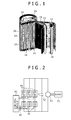
- Fig. 1 shows a non-aqueous secondary battery used in the invention (hereinafter also referred to simply as a battery or a lithium ion battery).
- a positive electrode plate 11 comprises a composite lithium oxide as an active material.
- a negative electrode plate 12 comprises a lithium ion retaining material as an active material.
- the positive electrode plate 11 and the negative electrode plate 12 are spirally wound by way of a separator 13 to provide a rolled-up electrode unit 22. Then the rolled-up electrode unit 22 is contained inside a bottomed cylindrical battery can 26.
- a negative electrode tab 24 led out from the lower part of the rolled-up electrode unit 22 is welded to the bottom of the battery can 26 and then a positive electrode tab 23 led out from the upper part of the rolled-up electrode unit 22 is welded to a battery cap 25.
- a predetermined electrolyte is poured into the battery can 26, and the battery cap 25 having an insulating gasket (not illustrated) at the periphery is attached and caulked to the opening of the battery can 26.
- the side of the axis of winding 21 is defined as an inner circumferential side 31 and the outside thereof is defined as an outer peripheral part 32.
- the positive electrode active material coated on the positive electrode plate 11 includes, for example, lithium cobaltate and modified products thereof (products formed by solid solubilizing aluminum or magnesium into lithium cobaltate), lithium nichelate and modified products thereof (products formed by partially substituting cobalt for nickel), lithium manganate and modified products thereof, and composite oxides thereof (containing nickel, cobalt, manganese).
- carbon blacks such as acetylene black, ketjen black, channel black, furnace black, lamp black, and thermal black, and various kinds of graphites can be used each alone or in combination.
- PVdF polyvinylidene fluoride
- PTFE polytetrafluoroethylene
- particulate rubber binder comprising acrylate units
- an acrylate monomer or an acrylate oligomer introduced with a reactive functional group can also be incorporated in the binder.
- binder for the negative electrode While PVdF and modified products thereof, as well as various kinds of binders can be used, it is more preferred to use styrenebutadiene copolymer rubber particles (SBR) and modified products thereof in combination with or with addition of a small amount of cellulose type resins such as carboxymethyl cellulose (CMC).
- SBR styrenebutadiene copolymer rubber particles
- CMC carboxymethyl cellulose
- carbon blacks such as acetylene black, ketjen black, channel black, furnace black, lamp black, and thermal black, and various kinds of graphites can be used, for example, each alone or in combination.
- the separator is not restricted particularly so long as the separator has a composition endurable within the range of use of the lithium ion secondary battery.
- a microporous film comprising an olefinic resin, for example, polyethylene or polypropylene may be used for the separator generally and preferably each alone or in a composite manner.
- the thickness of the separator is not particularly restricted and is preferably from 10 to 40 ⁇ m.
- electrolyte various kinds of lithium compounds such as LiPF 6 and LiBF 4 can be used as an electrolyte salt.
- ethylene carbonate (EC), dimethyl carbonate (DMC), diethyl carbonate (DEC), and methyl ethyl carbonate (MEC) can be used each alone or in combination.
- vinylene carbonate (VC), cyclohexyl benzene (CHB), and modified products thereof are used preferably to form a satisfactory film on the positive electrode and the negative electrode, thereby ensuring the stability upon overcharging or over-discharging.
- the shape of the rolled-up electrode unit in the invention is not necessarily be a normal cylindrical shape but may also be a shape such as length cylindrical shape having an elliptic rolled-up cross section or a quadrangular shape having a rectangular rolled-up cross section.
- a typical mode of use is as follows preferably.
- the rolled-up electrode unit and the electrolyte are filled in a bottomed cylindrical battery can and sealed in a state in which a tab for taking out current from the electrode plate is welded to the cap and the battery can.
- the present invention is not limited to such a mode.
- the battery can for filling the rolled-up electrode unit is not particularly restricted and those exhibiting the good performance in strength, corrosion resistance, and machinability such as a battery can plated on iron or stainless steel battery are preferred to provide corrosion resistance. Further, for the battery can, aluminum alloys or various kinds of engineering plastics can be used for reduction in weight and various kinds of engineering plastics and metals can be used in combination.
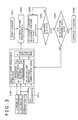
- FIG. 2 shows a secondary battery system.
- a lithium ion battery module 41 comprises a plurality of the batteries described above assembled in series, parallel, or serial-parallel connection.
- the secondary battery system is provided with a control device (entire controller) 61.
- the control device 61 has a battery state detection device for detecting battery voltage, charge and discharge current, and battery surface temperature of the lithium ion battery module 41 (measuring device) 42. Further, the control device 61 calculates electric resistance, quantity of cumulative charge/discharge electricity, and cumulative operation time based on the detected values.
- the battery resistance Z of the lithium ion battery module 41 can be represents by the formula (1) assuming a terminal voltage as V, an open voltage as V 0 and a current as I of the lithium ion battery module 41.
- the discharge side is defined as " + ".
- the formula (2) is derived from the formula (1) and the battery resistance Z can be calculated.
- the lithium ion battery module 41 and power switching devices 43 are combined in series, and the control device 61 transmits a control signal by way of a control signal transmission device 44 to the power switching device 43 in accordance with a detected value obtained from the battery state detection device 42 of the lithium ion battery module 41 and the amount of a demanded power from an electric load 71.
- the control device 61 includes a microcomputer having CPU, ROM, and RAM and operated in accordance with a predetermined program. Then, the control device 61 controls charging and discharging to the lithium ion battery module 41 based on the detected value obtained from the battery state detection device 42.
- a voltage detection means as the battery state detection device 42 detects the voltage on the lithium ion battery module.
- the battery voltage to be detected conceivably includes the voltage on one of batteries constituting the lithium ion battery module 41, the voltage on a battery group comprising a plurality of batteries connected in series, or the voltage on assembled batteries comprising a plurality of batteries in serial and parallel connection, but it is not particularly restricted.
- a current detection device detects the value of charge and discharge current. While instruments used in the detection method conceivably include a galvanometer, a galvanometer using a shunt resistor, and a clamp meter, they are not restrictive but any of means capable of detecting current values can be used.
- a temperature detection device detects the temperature of the lithium ion battery module 41. While devices for detecting temperature conceivably include a thermocouple, a thermister, etc., they are not restricted particularly. Examples of the place where temperature is to be detected includes the surface of the battery, the inside of the battery, the surface of a casing containing the lithium ion battery, and the environment of the lithium ion battery module 41.
- the power switching device 43 may include, for example, a semiconductor switch, a mechanical switch, an inverter or a DC-DC converter as power conversion equipment, etc., the power switching device 43 are not limited thereto and any of devices capable of controlling the current value upon charging and discharging to the lithium ion battery module 41 may be used.
- the power conversion device 51 is a device which converts a DC current obtained from the lithium ion battery into an AC current in response to the load.
- an inverter is preferably used as the power conversion device 51.
- a capacitor 52 is connected in parallel with the power conversion device 51. Even if power supply to the power conversion device 51 is reduced to 0 instantaneously, current is discharged from the capacitor 52, thereby allowing stable power to be supplied to the power converter 51.
- the electric load 71 may be a heater, an electric brake, an electric power steering, or an electric motor, for example, in the use to an automobile.
- Fig. 3 is a flow chart of a secondary battery system according to this embodiment.
- an instruction for starting charging to the lithium ion battery module 41 is sent as a signal from the control device 61 to the lithium ion battery module 41 to be charged.
- the battery resistance R of the lithium ion battery module 41 is estimated. Details as to how to estimate will be described in the step S101.
- a battery resistance R just before charging is estimated. More specifically, a battery resistance R' in a standard state is first calculated periodically, for example, upon maintenance of the lithium ion battery module 41. The calculation method is shown by the formula (2). While the standard state is not particularly restricted, SOC of 50% and temperature of 30°C, i.e., such conditions that the degradation of the lithium ion battery does not develop as much as possible, are desirable.
- an inter-terminal voltage V and a battery temperature T of the lithium ion battery module 41 are detected by the battery state detection device 42 in Fig. 2 and SOC is calculated based on the inter-terminal voltage of the lithium ion battery module 41 at the step S011. Then, the initial battery resistance R 0 corresponding to the current SOC and battery temperature is retrieved from the initial battery resistance correlation table in Fig. 4 .
- charge current I to charge is represented by the formula (5) assuming the inter-terminal voltage as V, the maximum allowable voltage as V k , and the estimated battery resistance as R for the lithium ion battery module 41.
- ⁇ is an adjusting value, for which variations between batteries (standard deviation, etc.) may be used but is not particularly restricted.
- the charge current I is set repeatedly.
- the newly set value of charge current I is smaller than the previously set value.
- the lithium ion battery module 41 is charged.
- the inter-terminal voltage of the lithium ion battery module 41 reaches a maximum allowable voltage V K
- charging is stopped and a charge stop signal is sent to the control device 61.
- the flow proceeds to the step S005.
- the inter-terminal voltage V of the lithium ion battery module 41 is lower than the maximum allowable voltage V k , charging is continued.
- step S005 SOC of the lithium ion battery module 41 is calculated again.
- the flow proceeds to the step S006, at which charging is completed.
- the flow proceeds to the step S101, at which the battery resistance R of the lithium ion battery module 41 is calculated again.
- the lithium ion battery module 41 can be charged by the control of detecting the state of the battery of the lithium ion battery module 41 by the battery state detection device 42, estimating the battery resistance R of the lithium battery module 41 based on the detected value and the initial battery resistance correlation table, and setting the charge current I, wherein the maximum allowable voltage is not reached due to over voltage. Accordingly, lowering of the battery capacity and increase in the battery resistance of the lithium ion battery can be suppressed, thereby providing a long life secondary battery system.
- the invention is applicable also to a stacked type lithium ion battery where a plurality of positive electrode plates and a plurality of negative electrode plates are stacked alternately by way of separators respectively.
Landscapes
- Engineering & Computer Science (AREA)
- Manufacturing & Machinery (AREA)
- Chemical & Material Sciences (AREA)
- Chemical Kinetics & Catalysis (AREA)
- Electrochemistry (AREA)
- General Chemical & Material Sciences (AREA)
- Microelectronics & Electronic Packaging (AREA)
- Charge And Discharge Circuits For Batteries Or The Like (AREA)
- Secondary Cells (AREA)
- Tests Of Electric Status Of Batteries (AREA)
- Battery Mounting, Suspending (AREA)
Applications Claiming Priority (1)
| Application Number | Priority Date | Filing Date | Title |
|---|---|---|---|
| JP2011143722A JP5337842B2 (ja) | 2011-06-29 | 2011-06-29 | 二次電池システム |
Publications (2)
| Publication Number | Publication Date |
|---|---|
| EP2541667A1 true EP2541667A1 (fr) | 2013-01-02 |
| EP2541667B1 EP2541667B1 (fr) | 2017-03-08 |
Family
ID=46397065
Family Applications (1)
| Application Number | Title | Priority Date | Filing Date |
|---|---|---|---|
| EP12174267.0A Active EP2541667B1 (fr) | 2011-06-29 | 2012-06-29 | Système de batterie secondaire |
Country Status (3)
| Country | Link |
|---|---|
| US (1) | US8994322B2 (fr) |
| EP (1) | EP2541667B1 (fr) |
| JP (1) | JP5337842B2 (fr) |
Cited By (1)
| Publication number | Priority date | Publication date | Assignee | Title |
|---|---|---|---|---|
| CN107359378A (zh) * | 2017-06-30 | 2017-11-17 | 宁德时代新能源科技股份有限公司 | 电池充电方法、装置和设备 |
Families Citing this family (11)
| Publication number | Priority date | Publication date | Assignee | Title |
|---|---|---|---|---|
| US9128159B2 (en) * | 2012-12-12 | 2015-09-08 | GM Global Technology Operations LLC | Plug-in charge capacity estimation method for lithium iron-phosphate batteries |
| KR102072247B1 (ko) * | 2013-07-16 | 2020-01-31 | 현대모비스 주식회사 | 배터리팩의 온도 관리 시스템 및 방법 |
| CN103364736B (zh) * | 2013-07-17 | 2015-07-22 | 王凯敏 | 一种锂离子电池组剩余可用容量rac的计算方法 |
| KR20150041329A (ko) * | 2013-10-08 | 2015-04-16 | 삼성전자주식회사 | 모바일 네트워크에서 트래픽 전송 방법 및 장치 |
| CN104157920B (zh) * | 2014-08-29 | 2016-08-17 | 合肥国轩高科动力能源有限公司 | 一种用于高能量密度锂离子电池的化成方法 |
| JP6256765B2 (ja) * | 2014-09-10 | 2018-01-10 | トヨタ自動車株式会社 | 充電状態推定方法 |
| US10094880B2 (en) | 2015-04-14 | 2018-10-09 | Semiconductor Components Industries, Llc | Determining battery state of charge using an open circuit voltage measured prior to a device operation stage |
| CN105403842A (zh) * | 2015-12-07 | 2016-03-16 | 高新兴科技集团股份有限公司 | 一种多次放电精密测量蓄电池内阻的方法 |
| JP2019114324A (ja) * | 2016-03-28 | 2019-07-11 | 株式会社日立製作所 | 二次電池システム |
| CN110681616A (zh) * | 2019-11-13 | 2020-01-14 | 洛阳超特电源科技有限公司 | 一种锂离子电池直流内阻的测试方法以及锂离子电池的分选方法 |
| JP7427944B2 (ja) * | 2019-12-06 | 2024-02-06 | 株式会社Gsユアサ | 制御装置、劣化推定システム、制御方法、及びコンピュータプログラム |
Citations (4)
| Publication number | Priority date | Publication date | Assignee | Title |
|---|---|---|---|---|
| US5132626A (en) * | 1989-05-31 | 1992-07-21 | Amoco Corporation | Electrolytic storage cell monitoring system |
| JPH0452080B2 (fr) | 1985-03-29 | 1992-08-20 | Sanken Electric Co Ltd | |
| US5307001A (en) * | 1992-05-05 | 1994-04-26 | Dimensions Unlimited, Inc. | Battery charging method and apparatus |
| US20100185405A1 (en) * | 2009-01-13 | 2010-07-22 | Hitachi Vehicle Energy, Ltd. | Battery Control Device |
Family Cites Families (23)
| Publication number | Priority date | Publication date | Assignee | Title |
|---|---|---|---|---|
| GR1001561B (el) * | 1993-03-19 | 1994-04-29 | Eleytherios Tsantilis | Βηματικό σύστημα φόρτισης,αλληλεπιδραστικά αυτοπροσαρμοζόμενο στήν ονομαστική ηλεκτρική τάση της μπαταρίας. |
| JP3559900B2 (ja) * | 2000-07-18 | 2004-09-02 | 日産自動車株式会社 | 組電池診断装置 |
| US7400113B2 (en) * | 2001-03-30 | 2008-07-15 | Designline International Holdings, Llc | Battery management unit, system and method |
| JP3929264B2 (ja) * | 2001-07-30 | 2007-06-13 | 富士通株式会社 | 二次電池の充電装置およびその方法 |
| JP3839761B2 (ja) * | 2001-09-14 | 2006-11-01 | 松下電器産業株式会社 | バッテリ制御装置 |
| KR100412688B1 (ko) * | 2001-12-18 | 2003-12-31 | 현대자동차주식회사 | 하이브리드 전기 자동차의 배터리 충전 상태 리셋 방법 |
| JP4052080B2 (ja) | 2002-10-09 | 2008-02-27 | アイシン・エィ・ダブリュ株式会社 | 車輌の制御装置 |
| JP2006112786A (ja) * | 2004-10-12 | 2006-04-27 | Sanyo Electric Co Ltd | 電池の残容量検出方法及び電源装置 |
| JP4817647B2 (ja) * | 2004-11-29 | 2011-11-16 | 三洋電機株式会社 | 二次電池の寿命判定方法。 |
| JP5050325B2 (ja) * | 2005-07-12 | 2012-10-17 | 日産自動車株式会社 | 組電池用制御装置 |
| KR100669470B1 (ko) * | 2005-12-22 | 2007-01-16 | 삼성에스디아이 주식회사 | 배터리의 soo 보정 방법 및 이를 이용한 배터리 관리시스템 |
| JP2007295707A (ja) * | 2006-04-24 | 2007-11-08 | Gs Yuasa Corporation:Kk | 移動体搭載用のリチウムイオン電池充電装置 |
| JP4987581B2 (ja) * | 2007-06-15 | 2012-07-25 | 日立ビークルエナジー株式会社 | 電池制御装置 |
| JP5386075B2 (ja) * | 2007-09-28 | 2014-01-15 | 株式会社日立製作所 | 多直列電池制御システム |
| JP5469813B2 (ja) * | 2008-01-29 | 2014-04-16 | 株式会社日立製作所 | 車両用電池システム |
| KR100970841B1 (ko) * | 2008-08-08 | 2010-07-16 | 주식회사 엘지화학 | 배터리 전압 거동을 이용한 배터리 용량 퇴화 추정 장치 및방법 |
| JP5331450B2 (ja) * | 2008-11-07 | 2013-10-30 | 株式会社日立製作所 | 蓄電モジュール、蓄電装置、電動機駆動システムおよび車両 |
| JP5221468B2 (ja) * | 2009-02-27 | 2013-06-26 | 株式会社日立製作所 | 電池監視装置 |
| JP2010223768A (ja) * | 2009-03-24 | 2010-10-07 | Panasonic Corp | 電池異常検出回路、及び電源装置 |
| JP5656415B2 (ja) * | 2009-03-26 | 2015-01-21 | プライムアースEvエナジー株式会社 | 二次電池の状態判定装置及び制御装置 |
| JP2010246225A (ja) * | 2009-04-03 | 2010-10-28 | Sony Corp | 電池パックおよび充電方法 |
| TW201103220A (en) * | 2009-07-06 | 2011-01-16 | Shun-Hsing Wang | Apparatus and method for managing plural secondary batteries |
| KR101147202B1 (ko) * | 2010-10-13 | 2012-05-25 | 삼성에스디아이 주식회사 | 전력 저장 장치 |
-
2011
- 2011-06-29 JP JP2011143722A patent/JP5337842B2/ja active Active
-
2012
- 2012-06-28 US US13/535,410 patent/US8994322B2/en active Active
- 2012-06-29 EP EP12174267.0A patent/EP2541667B1/fr active Active
Patent Citations (4)
| Publication number | Priority date | Publication date | Assignee | Title |
|---|---|---|---|---|
| JPH0452080B2 (fr) | 1985-03-29 | 1992-08-20 | Sanken Electric Co Ltd | |
| US5132626A (en) * | 1989-05-31 | 1992-07-21 | Amoco Corporation | Electrolytic storage cell monitoring system |
| US5307001A (en) * | 1992-05-05 | 1994-04-26 | Dimensions Unlimited, Inc. | Battery charging method and apparatus |
| US20100185405A1 (en) * | 2009-01-13 | 2010-07-22 | Hitachi Vehicle Energy, Ltd. | Battery Control Device |
Cited By (1)
| Publication number | Priority date | Publication date | Assignee | Title |
|---|---|---|---|---|
| CN107359378A (zh) * | 2017-06-30 | 2017-11-17 | 宁德时代新能源科技股份有限公司 | 电池充电方法、装置和设备 |
Also Published As
| Publication number | Publication date |
|---|---|
| US8994322B2 (en) | 2015-03-31 |
| JP5337842B2 (ja) | 2013-11-06 |
| JP2013013210A (ja) | 2013-01-17 |
| EP2541667B1 (fr) | 2017-03-08 |
| US20130002194A1 (en) | 2013-01-03 |
Similar Documents
| Publication | Publication Date | Title |
|---|---|---|
| EP2541667B1 (fr) | Système de batterie secondaire | |
| EP2482375A1 (fr) | Système de batterie rechargeable | |
| JP5298095B2 (ja) | 二次電池システム | |
| CN101855773B (zh) | 具有用于健康状态监视的参考电极的锂可再充电电池 | |
| JP5326517B2 (ja) | 集積回路およびそれを用いた電池パック | |
| JP5010051B2 (ja) | リチウム二次電池における正極活物質の充放電方法、ならびに、リチウム二次電池を備えた充放電システム、電池パック、電池モジュール、電子機器および車両 | |
| US20200355749A1 (en) | Device detecting abnormality of secondary battery, abnormality detection method, and program | |
| US10135267B2 (en) | Secondary battery system | |
| WO2013157132A1 (fr) | Système de batterie secondaire et procédé de détermination d'état de dégradation de batterie secondaire | |
| EP2291669B1 (fr) | Procédé de diagnostic d'un défaut de fonctionnement dans un appareil de détection de tension anormale, système à batterie secondaire et véhicule hybride | |
| JP5771512B2 (ja) | 二次電池システム、二次電池システムを用いた二次電池モジュールおよび二次電池の制御方法 | |
| JP7396481B2 (ja) | 二次電池、電子機器及び電動工具 | |
| US12074467B2 (en) | Secondary battery charging system | |
| JP7608132B2 (ja) | リチウムイオン二次電池の制御方法 | |
| JP7508346B2 (ja) | リチウムイオン二次電池の制御方法 | |
| JP2021044151A (ja) | リチウムイオン電池モジュール及びリチウムイオン電池モジュールの充電方法 |
Legal Events
| Date | Code | Title | Description |
|---|---|---|---|
| PUAI | Public reference made under article 153(3) epc to a published international application that has entered the european phase |
Free format text: ORIGINAL CODE: 0009012 |
|
| 17P | Request for examination filed |
Effective date: 20121019 |
|
| AK | Designated contracting states |
Kind code of ref document: A1 Designated state(s): AL AT BE BG CH CY CZ DE DK EE ES FI FR GB GR HR HU IE IS IT LI LT LU LV MC MK MT NL NO PL PT RO RS SE SI SK SM TR |
|
| AX | Request for extension of the european patent |
Extension state: BA ME |
|
| GRAP | Despatch of communication of intention to grant a patent |
Free format text: ORIGINAL CODE: EPIDOSNIGR1 |
|
| STAA | Information on the status of an ep patent application or granted ep patent |
Free format text: STATUS: GRANT OF PATENT IS INTENDED |
|
| INTG | Intention to grant announced |
Effective date: 20161107 |
|
| RIC1 | Information provided on ipc code assigned before grant |
Ipc: H01M 10/42 20060101ALI20161025BHEP Ipc: H01M 10/48 20060101ALI20161025BHEP Ipc: H01M 10/44 20060101AFI20161025BHEP Ipc: H02J 7/00 20060101ALI20161025BHEP |
|
| GRAS | Grant fee paid |
Free format text: ORIGINAL CODE: EPIDOSNIGR3 |
|
| GRAA | (expected) grant |
Free format text: ORIGINAL CODE: 0009210 |
|
| STAA | Information on the status of an ep patent application or granted ep patent |
Free format text: STATUS: THE PATENT HAS BEEN GRANTED |
|
| AK | Designated contracting states |
Kind code of ref document: B1 Designated state(s): AL AT BE BG CH CY CZ DE DK EE ES FI FR GB GR HR HU IE IS IT LI LT LU LV MC MK MT NL NO PL PT RO RS SE SI SK SM TR |
|
| REG | Reference to a national code |
Ref country code: GB Ref legal event code: FG4D |
|
| REG | Reference to a national code |
Ref country code: CH Ref legal event code: EP Ref country code: AT Ref legal event code: REF Ref document number: 874297 Country of ref document: AT Kind code of ref document: T Effective date: 20170315 |
|
| REG | Reference to a national code |
Ref country code: IE Ref legal event code: FG4D |
|
| REG | Reference to a national code |
Ref country code: DE Ref legal event code: R096 Ref document number: 602012029496 Country of ref document: DE |
|
| REG | Reference to a national code |
Ref country code: LT Ref legal event code: MG4D |
|
| REG | Reference to a national code |
Ref country code: NL Ref legal event code: MP Effective date: 20170308 |
|
| PG25 | Lapsed in a contracting state [announced via postgrant information from national office to epo] |
Ref country code: NO Free format text: LAPSE BECAUSE OF FAILURE TO SUBMIT A TRANSLATION OF THE DESCRIPTION OR TO PAY THE FEE WITHIN THE PRESCRIBED TIME-LIMIT Effective date: 20170608 Ref country code: LT Free format text: LAPSE BECAUSE OF FAILURE TO SUBMIT A TRANSLATION OF THE DESCRIPTION OR TO PAY THE FEE WITHIN THE PRESCRIBED TIME-LIMIT Effective date: 20170308 Ref country code: HR Free format text: LAPSE BECAUSE OF FAILURE TO SUBMIT A TRANSLATION OF THE DESCRIPTION OR TO PAY THE FEE WITHIN THE PRESCRIBED TIME-LIMIT Effective date: 20170308 Ref country code: FI Free format text: LAPSE BECAUSE OF FAILURE TO SUBMIT A TRANSLATION OF THE DESCRIPTION OR TO PAY THE FEE WITHIN THE PRESCRIBED TIME-LIMIT Effective date: 20170308 Ref country code: GR Free format text: LAPSE BECAUSE OF FAILURE TO SUBMIT A TRANSLATION OF THE DESCRIPTION OR TO PAY THE FEE WITHIN THE PRESCRIBED TIME-LIMIT Effective date: 20170609 |
|
| REG | Reference to a national code |
Ref country code: AT Ref legal event code: MK05 Ref document number: 874297 Country of ref document: AT Kind code of ref document: T Effective date: 20170308 |
|
| PG25 | Lapsed in a contracting state [announced via postgrant information from national office to epo] |
Ref country code: RS Free format text: LAPSE BECAUSE OF FAILURE TO SUBMIT A TRANSLATION OF THE DESCRIPTION OR TO PAY THE FEE WITHIN THE PRESCRIBED TIME-LIMIT Effective date: 20170308 Ref country code: LV Free format text: LAPSE BECAUSE OF FAILURE TO SUBMIT A TRANSLATION OF THE DESCRIPTION OR TO PAY THE FEE WITHIN THE PRESCRIBED TIME-LIMIT Effective date: 20170308 Ref country code: SE Free format text: LAPSE BECAUSE OF FAILURE TO SUBMIT A TRANSLATION OF THE DESCRIPTION OR TO PAY THE FEE WITHIN THE PRESCRIBED TIME-LIMIT Effective date: 20170308 Ref country code: BG Free format text: LAPSE BECAUSE OF FAILURE TO SUBMIT A TRANSLATION OF THE DESCRIPTION OR TO PAY THE FEE WITHIN THE PRESCRIBED TIME-LIMIT Effective date: 20170608 Ref country code: ES Free format text: LAPSE BECAUSE OF FAILURE TO SUBMIT A TRANSLATION OF THE DESCRIPTION OR TO PAY THE FEE WITHIN THE PRESCRIBED TIME-LIMIT Effective date: 20170308 |
|
| PG25 | Lapsed in a contracting state [announced via postgrant information from national office to epo] |
Ref country code: NL Free format text: LAPSE BECAUSE OF FAILURE TO SUBMIT A TRANSLATION OF THE DESCRIPTION OR TO PAY THE FEE WITHIN THE PRESCRIBED TIME-LIMIT Effective date: 20170308 |
|
| PG25 | Lapsed in a contracting state [announced via postgrant information from national office to epo] |
Ref country code: SK Free format text: LAPSE BECAUSE OF FAILURE TO SUBMIT A TRANSLATION OF THE DESCRIPTION OR TO PAY THE FEE WITHIN THE PRESCRIBED TIME-LIMIT Effective date: 20170308 Ref country code: CZ Free format text: LAPSE BECAUSE OF FAILURE TO SUBMIT A TRANSLATION OF THE DESCRIPTION OR TO PAY THE FEE WITHIN THE PRESCRIBED TIME-LIMIT Effective date: 20170308 Ref country code: EE Free format text: LAPSE BECAUSE OF FAILURE TO SUBMIT A TRANSLATION OF THE DESCRIPTION OR TO PAY THE FEE WITHIN THE PRESCRIBED TIME-LIMIT Effective date: 20170308 Ref country code: IT Free format text: LAPSE BECAUSE OF FAILURE TO SUBMIT A TRANSLATION OF THE DESCRIPTION OR TO PAY THE FEE WITHIN THE PRESCRIBED TIME-LIMIT Effective date: 20170308 Ref country code: AT Free format text: LAPSE BECAUSE OF FAILURE TO SUBMIT A TRANSLATION OF THE DESCRIPTION OR TO PAY THE FEE WITHIN THE PRESCRIBED TIME-LIMIT Effective date: 20170308 Ref country code: RO Free format text: LAPSE BECAUSE OF FAILURE TO SUBMIT A TRANSLATION OF THE DESCRIPTION OR TO PAY THE FEE WITHIN THE PRESCRIBED TIME-LIMIT Effective date: 20170308 |
|
| PG25 | Lapsed in a contracting state [announced via postgrant information from national office to epo] |
Ref country code: SM Free format text: LAPSE BECAUSE OF FAILURE TO SUBMIT A TRANSLATION OF THE DESCRIPTION OR TO PAY THE FEE WITHIN THE PRESCRIBED TIME-LIMIT Effective date: 20170308 Ref country code: PT Free format text: LAPSE BECAUSE OF FAILURE TO SUBMIT A TRANSLATION OF THE DESCRIPTION OR TO PAY THE FEE WITHIN THE PRESCRIBED TIME-LIMIT Effective date: 20170710 Ref country code: PL Free format text: LAPSE BECAUSE OF FAILURE TO SUBMIT A TRANSLATION OF THE DESCRIPTION OR TO PAY THE FEE WITHIN THE PRESCRIBED TIME-LIMIT Effective date: 20170308 Ref country code: IS Free format text: LAPSE BECAUSE OF FAILURE TO SUBMIT A TRANSLATION OF THE DESCRIPTION OR TO PAY THE FEE WITHIN THE PRESCRIBED TIME-LIMIT Effective date: 20170708 |
|
| REG | Reference to a national code |
Ref country code: DE Ref legal event code: R097 Ref document number: 602012029496 Country of ref document: DE |
|
| PLBE | No opposition filed within time limit |
Free format text: ORIGINAL CODE: 0009261 |
|
| STAA | Information on the status of an ep patent application or granted ep patent |
Free format text: STATUS: NO OPPOSITION FILED WITHIN TIME LIMIT |
|
| PG25 | Lapsed in a contracting state [announced via postgrant information from national office to epo] |
Ref country code: MC Free format text: LAPSE BECAUSE OF FAILURE TO SUBMIT A TRANSLATION OF THE DESCRIPTION OR TO PAY THE FEE WITHIN THE PRESCRIBED TIME-LIMIT Effective date: 20170308 Ref country code: DK Free format text: LAPSE BECAUSE OF FAILURE TO SUBMIT A TRANSLATION OF THE DESCRIPTION OR TO PAY THE FEE WITHIN THE PRESCRIBED TIME-LIMIT Effective date: 20170308 |
|
| REG | Reference to a national code |
Ref country code: CH Ref legal event code: PL |
|
| 26N | No opposition filed |
Effective date: 20171211 |
|
| GBPC | Gb: european patent ceased through non-payment of renewal fee |
Effective date: 20170629 |
|
| PG25 | Lapsed in a contracting state [announced via postgrant information from national office to epo] |
Ref country code: SI Free format text: LAPSE BECAUSE OF FAILURE TO SUBMIT A TRANSLATION OF THE DESCRIPTION OR TO PAY THE FEE WITHIN THE PRESCRIBED TIME-LIMIT Effective date: 20170308 |
|
| REG | Reference to a national code |
Ref country code: FR Ref legal event code: ST Effective date: 20180228 |
|
| REG | Reference to a national code |
Ref country code: IE Ref legal event code: MM4A |
|
| PG25 | Lapsed in a contracting state [announced via postgrant information from national office to epo] |
Ref country code: IE Free format text: LAPSE BECAUSE OF NON-PAYMENT OF DUE FEES Effective date: 20170629 Ref country code: LI Free format text: LAPSE BECAUSE OF NON-PAYMENT OF DUE FEES Effective date: 20170630 Ref country code: GB Free format text: LAPSE BECAUSE OF NON-PAYMENT OF DUE FEES Effective date: 20170629 Ref country code: LU Free format text: LAPSE BECAUSE OF NON-PAYMENT OF DUE FEES Effective date: 20170629 Ref country code: CH Free format text: LAPSE BECAUSE OF NON-PAYMENT OF DUE FEES Effective date: 20170630 |
|
| PG25 | Lapsed in a contracting state [announced via postgrant information from national office to epo] |
Ref country code: FR Free format text: LAPSE BECAUSE OF NON-PAYMENT OF DUE FEES Effective date: 20170630 |
|
| REG | Reference to a national code |
Ref country code: BE Ref legal event code: MM Effective date: 20170630 |
|
| PG25 | Lapsed in a contracting state [announced via postgrant information from national office to epo] |
Ref country code: BE Free format text: LAPSE BECAUSE OF NON-PAYMENT OF DUE FEES Effective date: 20170630 |
|
| PG25 | Lapsed in a contracting state [announced via postgrant information from national office to epo] |
Ref country code: MT Free format text: LAPSE BECAUSE OF NON-PAYMENT OF DUE FEES Effective date: 20170629 |
|
| PG25 | Lapsed in a contracting state [announced via postgrant information from national office to epo] |
Ref country code: HU Free format text: LAPSE BECAUSE OF FAILURE TO SUBMIT A TRANSLATION OF THE DESCRIPTION OR TO PAY THE FEE WITHIN THE PRESCRIBED TIME-LIMIT; INVALID AB INITIO Effective date: 20120629 |
|
| PG25 | Lapsed in a contracting state [announced via postgrant information from national office to epo] |
Ref country code: CY Free format text: LAPSE BECAUSE OF NON-PAYMENT OF DUE FEES Effective date: 20170308 |
|
| PG25 | Lapsed in a contracting state [announced via postgrant information from national office to epo] |
Ref country code: MK Free format text: LAPSE BECAUSE OF FAILURE TO SUBMIT A TRANSLATION OF THE DESCRIPTION OR TO PAY THE FEE WITHIN THE PRESCRIBED TIME-LIMIT Effective date: 20170308 |
|
| PG25 | Lapsed in a contracting state [announced via postgrant information from national office to epo] |
Ref country code: TR Free format text: LAPSE BECAUSE OF FAILURE TO SUBMIT A TRANSLATION OF THE DESCRIPTION OR TO PAY THE FEE WITHIN THE PRESCRIBED TIME-LIMIT Effective date: 20170308 |
|
| PG25 | Lapsed in a contracting state [announced via postgrant information from national office to epo] |
Ref country code: AL Free format text: LAPSE BECAUSE OF FAILURE TO SUBMIT A TRANSLATION OF THE DESCRIPTION OR TO PAY THE FEE WITHIN THE PRESCRIBED TIME-LIMIT Effective date: 20170308 |
|
| PGFP | Annual fee paid to national office [announced via postgrant information from national office to epo] |
Ref country code: DE Payment date: 20250507 Year of fee payment: 14 |