EP2541684A1 - Anschluss zum Verbinden von zwei Stromkabeln - Google Patents
Anschluss zum Verbinden von zwei Stromkabeln Download PDFInfo
- Publication number
- EP2541684A1 EP2541684A1 EP12173702A EP12173702A EP2541684A1 EP 2541684 A1 EP2541684 A1 EP 2541684A1 EP 12173702 A EP12173702 A EP 12173702A EP 12173702 A EP12173702 A EP 12173702A EP 2541684 A1 EP2541684 A1 EP 2541684A1
- Authority
- EP
- European Patent Office
- Prior art keywords
- cables
- jaw
- nail
- jaws
- face
- Prior art date
- Legal status (The legal status is an assumption and is not a legal conclusion. Google has not performed a legal analysis and makes no representation as to the accuracy of the status listed.)
- Withdrawn
Links
- 239000011324 bead Substances 0.000 claims description 10
- 229910052751 metal Inorganic materials 0.000 claims description 6
- 239000002184 metal Substances 0.000 claims description 6
- 230000003014 reinforcing effect Effects 0.000 claims description 6
- 239000011810 insulating material Substances 0.000 claims description 3
- 230000007704 transition Effects 0.000 claims description 2
- 208000031968 Cadaver Diseases 0.000 description 8
- 230000035515 penetration Effects 0.000 description 7
- 229910052782 aluminium Inorganic materials 0.000 description 4
- XAGFODPZIPBFFR-UHFFFAOYSA-N aluminium Chemical compound [Al] XAGFODPZIPBFFR-UHFFFAOYSA-N 0.000 description 4
- 239000000463 material Substances 0.000 description 2
- RYGMFSIKBFXOCR-UHFFFAOYSA-N Copper Chemical compound [Cu] RYGMFSIKBFXOCR-UHFFFAOYSA-N 0.000 description 1
- 229910000831 Steel Inorganic materials 0.000 description 1
- 238000012550 audit Methods 0.000 description 1
- 230000000295 complement effect Effects 0.000 description 1
- 229910052802 copper Inorganic materials 0.000 description 1
- 239000010949 copper Substances 0.000 description 1
- 230000000694 effects Effects 0.000 description 1
- 239000012212 insulator Substances 0.000 description 1
- 238000002955 isolation Methods 0.000 description 1
- 238000000926 separation method Methods 0.000 description 1
- 229910001220 stainless steel Inorganic materials 0.000 description 1
- 239000010935 stainless steel Substances 0.000 description 1
- 239000010959 steel Substances 0.000 description 1
Images


Classifications
-
- H—ELECTRICITY
- H01—ELECTRIC ELEMENTS
- H01R—ELECTRICALLY-CONDUCTIVE CONNECTIONS; STRUCTURAL ASSOCIATIONS OF A PLURALITY OF MUTUALLY-INSULATED ELECTRICAL CONNECTING ELEMENTS; COUPLING DEVICES; CURRENT COLLECTORS
- H01R4/00—Electrically-conductive connections between two or more conductive members in direct contact, i.e. touching one another; Means for effecting or maintaining such contact; Electrically-conductive connections having two or more spaced connecting locations for conductors and using contact members penetrating insulation
- H01R4/24—Connections using contact members penetrating or cutting insulation or cable strands
- H01R4/2404—Connections using contact members penetrating or cutting insulation or cable strands the contact members having teeth, prongs, pins or needles penetrating the insulation
- H01R4/2408—Connections using contact members penetrating or cutting insulation or cable strands the contact members having teeth, prongs, pins or needles penetrating the insulation actuated by clamping screws
-
- H—ELECTRICITY
- H01—ELECTRIC ELEMENTS
- H01R—ELECTRICALLY-CONDUCTIVE CONNECTIONS; STRUCTURAL ASSOCIATIONS OF A PLURALITY OF MUTUALLY-INSULATED ELECTRICAL CONNECTING ELEMENTS; COUPLING DEVICES; CURRENT COLLECTORS
- H01R13/00—Details of coupling devices of the kinds covered by groups H01R12/70 or H01R24/00 - H01R33/00
- H01R13/46—Bases; Cases
- H01R13/514—Bases; Cases composed as a modular blocks or assembly, i.e. composed of co-operating parts provided with contact members or holding contact members between them
-
- H—ELECTRICITY
- H01—ELECTRIC ELEMENTS
- H01R—ELECTRICALLY-CONDUCTIVE CONNECTIONS; STRUCTURAL ASSOCIATIONS OF A PLURALITY OF MUTUALLY-INSULATED ELECTRICAL CONNECTING ELEMENTS; COUPLING DEVICES; CURRENT COLLECTORS
- H01R4/00—Electrically-conductive connections between two or more conductive members in direct contact, i.e. touching one another; Means for effecting or maintaining such contact; Electrically-conductive connections having two or more spaced connecting locations for conductors and using contact members penetrating insulation
- H01R4/28—Clamped connections, spring connections
- H01R4/38—Clamped connections, spring connections utilising a clamping member acted on by screw or nut
- H01R4/44—Clamping areas on both sides of screw
-
- H—ELECTRICITY
- H01—ELECTRIC ELEMENTS
- H01R—ELECTRICALLY-CONDUCTIVE CONNECTIONS; STRUCTURAL ASSOCIATIONS OF A PLURALITY OF MUTUALLY-INSULATED ELECTRICAL CONNECTING ELEMENTS; COUPLING DEVICES; CURRENT COLLECTORS
- H01R11/00—Individual connecting elements providing two or more spaced connecting locations for conductive members which are, or may be, thereby interconnected, e.g. end pieces for wires or cables supported by the wire or cable and having means for facilitating electrical connection to some other wire, terminal, or conductive member, blocks of binding posts
- H01R11/03—Individual connecting elements providing two or more spaced connecting locations for conductive members which are, or may be, thereby interconnected, e.g. end pieces for wires or cables supported by the wire or cable and having means for facilitating electrical connection to some other wire, terminal, or conductive member, blocks of binding posts characterised by the relationship between the connecting locations
- H01R11/07—Individual connecting elements providing two or more spaced connecting locations for conductive members which are, or may be, thereby interconnected, e.g. end pieces for wires or cables supported by the wire or cable and having means for facilitating electrical connection to some other wire, terminal, or conductive member, blocks of binding posts characterised by the relationship between the connecting locations the connecting locations being of the same type but different sizes
-
- H—ELECTRICITY
- H01—ELECTRIC ELEMENTS
- H01R—ELECTRICALLY-CONDUCTIVE CONNECTIONS; STRUCTURAL ASSOCIATIONS OF A PLURALITY OF MUTUALLY-INSULATED ELECTRICAL CONNECTING ELEMENTS; COUPLING DEVICES; CURRENT COLLECTORS
- H01R4/00—Electrically-conductive connections between two or more conductive members in direct contact, i.e. touching one another; Means for effecting or maintaining such contact; Electrically-conductive connections having two or more spaced connecting locations for conductors and using contact members penetrating insulation
- H01R4/06—Riveted connections
Definitions
- the invention relates to connectors for connecting two electric cables to one another.
- the connector described by this document comprises: two jaws and a screw / nut pair to bring said jaws closer to each other, each said jaw comprising a body of rigid insulating material and a conductive contact member having two active parts projecting each a receiving face of the body respectively to penetrate the conductive core of a cable and the conductive core of the other cable, each receiving face of the body of each jaw being opposite the receiving face of the body of the other jaw with each active part of the contact member of a jaw to the right of an active part of the contact member of the other jaw, said connector admitting a positioning position of the cables between the receiving faces of the jaws with each active part of a contact member to the right of a cable and admitting a service position where the cables are sandwiched between the jaws with each other an active part which has penetrated into a conductive core of a respective cable, said connector being configured to pass from the position of placing the cables to the service position by bringing the jaws closer together with the screw / nut couple, a predetermined race.
- the invention aims to provide a similar connector simple, convenient and economical.
- the invention proposes for this purpose a connector for connecting two electric cables to each other, comprising two jaws and a clamping member for bringing said jaws closer to each other, each said jaw comprising a body made of material rigid insulator and a conductive contact member having two active parts each projecting from a receiving face of the body respectively to penetrate into the conductive core of one cable and into the conductive core of the other cable, the receiving face.
- each jaw being opposite the receiving face of the body of the other jaw with each active part of the contact member of a jaw to the right of an active part of the contact member of the another jaw, said connector being configured to take a position of placing the cables between the receiving faces of the jaws with each active part of a contact member to the right of a cable, to take a positi in use where the cables are sandwiched between the jaws with each active part of each contact member which has penetrated into a conductive core of a respective cable, and to move from the position of placing the cables to the position service by approximation of the jaws, with the clamping member, a predetermined stroke; characterized in that said clamping member is a blind rivet having a barrel and a nail, which blind rivet is configured so that the barrel contracts in the axial direction, under the action of the nail, between the position of placement of the cables and the service position, and configured so that the nail breaks when said jaws are closer to said predetermined stroke.
- the clamping member of the connector according to the invention is not a torque screw / nut but a blind rivet.
- the blind rivet drives the jaws towards one another to make them penetrate the cables.
- a blind rivet may have a jaw training function
- the Applicant's tests have shown that a blind rivet is capable of providing both the stroke and the effort required for the jaws penetrate the cables and the failure of the nail occurs exactly when the penetration depth required in the cables has been reached.
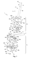
- the connector 1 represented in Figures 1 to 5 aims to electrically connect two cables 3 between them.
- This connector 1 comprises a first jaw 2a, a second jaw 2b and a blind rivet 4.
- Each jaw 2a, 2b comprises a body 20, two conductive contact members 21 and a gasket 23.
- Each body 20 is made of rigid insulating material. It is in the form of a shell having a receiving face 25, an end face 27 opposite to the receiving face 25 and four side faces 26a, 26b, 26c, 26d each extending from the receiving face. 25 to the end face 27. Of these, a first side face 26a is opposed to a second side face 26b.
- the receiving face 25 has two gutters 32 extending from the face 26a to the face 26b.
- Each body 20 is traversed by a housing 24 opening on the one hand on the end face 27 and on the other side on the receiving face 25, between the two gutters 32.
- a lug 50 protrudes from each side face 26a, 26b.
- Each lug 50 is located at the junction of the corresponding lateral face 26a, 26b with the receiving face 25, between the ends of the gutters 32 (see FIG. figure 3 ).
- each wall 51 extends towards the opposite of the receiving face 25.
- each wall 51 is in the form of a stirrup whose ends are located at the junction of the receiving face 25 and the corresponding lateral face 26a or 26b (see FIG. figure 2 ).
- the housing 24 of the first jaw 2a opens on the receiving face 25 by a circular contour orifice 53 and on the end face 27 by an orifice 52 with an oval contour.
- the housing 24 of the second jaw 2b has two cylindrical portions.
- a first portion of the housing 24 is a bore 33 which opens out on the receiving face 25.
- the other portion of the housing 24 is a countersink 29 of diameter greater than that of the bore 33. This countersink 29 opens on the end face 27 by a circular contour orifice 60.
- a metal washer 28 is attached to the bottom of the countersink 29.
- the washer 28 is secured to the body 20 because it is engaged by force in the countersink 29.
- the metal washer 28 is maintained by others means, for example by snapping.
- Each contact member 21 is a thin U-shaped metal plate having a central branch and two distal branches.
- the distal branches each comprise an active portion 22 at their end.
- Each active part 22 here comprises three pointed teeth arranged side by side. Alternatively, the number of teeth is different from three, for example two teeth or more than three teeth.
- Each gasket 23 comprises two envelopes 55a and 55b each designed to receive one of the contact members 21, leaving only the active portions 22 emerge, through a cradle 54a, 54b, 54c or 54d respectively. bow shape.
- Each envelope 55a and 55b comprises two side-by-side flanges delimiting a median housing 58 where a contact member 21 is placed by an orifice 59 opposite the cradles 54a and 54b or 54c and 54d.
- the envelopes 55a and 55b are connected by tile-shaped bridges 56a and 56b respectively arranged between the cradles 54b and 54c and between the cradles 54a and 54d.
- a protrusion 57 protrudes from each of the bridges 56a and 56b apart and facing the envelopes 55a and 55b.
- the seals 23 have no protuberance such as 57.
- the cables 3 are here of conventional type, each comprising a conductive core 30 and an insulating sheath 31.
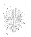
- the blind rivet 4 comprises a nail 40 and a hollow shaft 43.
- the nail 40 has a body 41 and a head 42.
- the shaft 43 has a body 44 and a head 45.
- the blind rivet 4 is configured to move from a crimped state ( figure 4 ) to a crimped state ( figure 5 ).
- the body 41 of the nail 40 is engaged in the body 44 of the barrel 43 and protrudes from the body 44 on the side of the head 45.
- the head 42 of the nail 40 is against the end of the body 44 opposite the head 45.
- the head 42 In the crimped state, the head 42 is forcibly engaged in the body 44, the body 44 has a bead 47 around the head 42 and the nail 40 is cut into a rupture zone 46.
- the shaft 43 is made of easily deformable metal, for example aluminum, stainless steel or annealed copper.
- the nail 40 is of low deformable material, for example hard steel.
- the body 41 has a necking (not shown) of predetermined conformation.
- the seals 23 enclosing the contact members 21 are each forced into the body 20 of the corresponding jaw 2a or 2b.
- Each seal 23 is complementary to a cavity on the respective body 20.
- the curvature of the cradles 54a, 54b, 54c, 54d follows that of the gutters 32.
- the jaws 2a and 2b are arranged with the receiving faces 25 facing each other.
- the lugs 50 are housed in the stirrups 51, holding the jaws 2a, 2b with each other while allowing them to move closer or move away within a predefined range.
- the blind rivet 4 in the crimped state is inserted by the head 42 in the oval-shaped orifice 52 to exit through the orifice 60.
- the blind rivet 4 is inserted slightly forcibly through the washer 28.
- the connector is then in a ready-to-use state.
- the jaws 2a, 2b can be moved closer together or apart from each other with the blind rivet 4 which remains in place.
- the body 44 of the barrel 43 is configured to protrude from the washer 28 when the jaws 2a, 2b are separated by the greatest thickness provided for the cables 3 and that the head 45 bears on the end face 27 of the jaw 2a. In the position of maximum separation of the jaws 2a and 2b fixed by the abutment of the lugs 50 against the bottom of the light defined by the corresponding wall 51, the barrel 44 is still in contact with the washer 28.
- the cables 3 are introduced laterally into the gutters 32.
- the two jaws 2a, 2b can be brought closer manually to put the active parts 22 in contact with the cables 3.
- the connector 1 is then in position for placing the cables ( figure 4 ).
- the blind rivet 4 is crimped using a rivet pliers (not shown).
- the rivet clamp is of conventional type comprising a mandrel.
- the mandrel is placed around the body 41 of the nail 40. It is movable relative to a stop that bears on the head 45 of the barrel 43.
- the body 41 is subjected by the mandrel to a traction or a series of pulls, thus bringing the blind rivet 4 of the state to crimp in the crimped state.
- the depth of penetration of the active parts 22 in the conductive core 30 of the cables is decisive for the quality of the electrical connection between the cables 3 and to preserve the integrity of the cables 3.
- the blind rivet 4 is therefore chosen to achieve its Crimped state when the desired penetration depth is reached.
- the barrel 43 When the blind rivet 4 is in the crimped state, the barrel 43 has an initial length greater than the sum of the thickness of the first jaw 2a, the thickness of the cables 3, the thickness of the second jaw 2b and the height of the head 42 of the nail 40.
- the thickness of the first jaw 2a is understood as the distance, in the direction of the blind rivet 4, between the edge of the oval-shaped orifice 52 and the end of an active part 22 of the first jaw 2a. in contact with one of the cables 3; and the thickness of the second jaw 2b is understood as the distance, in the direction of the blind rivet 4, between the engagement orifice 61 and the end of an active portion of the second jaw 2b in contact with the one of the cables 3.
- the blind rivet To reach the set state, the blind rivet must contract a length equal to the sum of the flattening of the cables 3 under the effect of their clamping between the jaws 2a and 2b, the penetration depth of the active parts. 22 of the first jaw 2a in the cables 3, the penetration depth of the active parts 22 of the second jaw 2b in the cables 3 and the depth of engagement of the head 42 of the nail 40 in the body 44 of the drum 43.
- the blind rivet 4 is in the crimped state and the connector 1 is in the service position.
- the cradles 54a, 54b, 54c and 54d then cover the active parts 22 around their respective point of penetration in the cables 3.
- the active parts 22 are then on the one hand isolated from any moisture present in the environment of the connector 1, on the other hand electrically insulated from the outside of the connector.
- the diameter of the bore 33 of the housing 24 of the second jaw 2b is greater than the outer diameter of the body 44 of the barrel 43 of the blind rivet 4 in the crimped state.
- the body 44 increases in width in the bore 33 or in the interstice between the jaws 2a, 2b.
- the housing 24 of the jaw 2a widens to reach the end face 27 through the oval-shaped orifice 52.
- This flared shape is provided for the jaw 2a to tilt. in a configuration where the electric cables 3 would be of different diameters.
- the head 45 of the barrel 43 engages on the periphery of one end of the oval-shaped orifice 52.
- the connector 1 is provided for cables 3 which each have a section between 1.5 mm 2 and 25 mm 2 .
- the body 41 of the nail 40 is dimensioned, for example by means of a calibrated frangible zone, to break under a tensile force of between 4500 N and 6500 N.
- a rivet is for example a rivet whose shaft 43 is made of aluminum with the body which has an outer diameter of about 4.8 mm.
- the movement of the jaws between the position of positioning of the cables ( figure 4 ) at the service position ( figure 5 ) is typically of the order of 11 mm.
- the tensile force is at least 4500 N makes it possible to be sure that the jaws have sufficiently penetrated the cables.
- the connector 1 is provided so that one of the cables 3 has a section of between 16 mm 2 and 95 mm 2 and for the other cable 3 has a section between 4 mm 2 and 35 mm 2 .
- the body 41 of the nail 40 is dimensioned, for example by means of a calibrated frangible zone, to break under a tensile force of between 8500 N and 10500 N.
- a rivet is for example a rivet whose shaft 43 is made of aluminum with the body which has an outer diameter of the order of 5.3 mm.
- the movement of the jaws between the position of positioning of the cables ( figure 4 ) at the service position ( figure 5 ) is typically of the order of 13 mm.
- the connector 1 is provided for cables 3 which each have a section of between 16 mm 2 and 95 mm 2 .
- the body 41 of the nail 40 is dimensioned, for example by means of a calibrated frangible zone, to break under a tensile force of between 11000 N and 13000 N.
- a rivet is for example a rivet whose shaft 43 is made of aluminum with the body which has an outer diameter of about 6.3 mm.
- the movement of the jaws between the position of positioning of the cables ( figure 4 ) at the service position ( figure 5 ) is typically of the order of 13 mm.
- the jaws 2a, 2b of the connector do not have a seal 23 and / or the number of contact members 21 is different from two, for example one or more than two.
- the body 44 of the barrel 43 is preserti on assembly, that is to say that the bead 47 is primed.
- the rivet 4 is thus captive.
- the means of imperdability are different, for example a latching lug on the jaw 2b and a cavity formed externally in the body 44 of the barrel 43 to receive the latching lug.
- the washer 28 constitutes a reinforcing member allowing the bead 47 to engage the jaw 2b.
- the reinforcing member is different from the washer 28, with for example, a greater thickness in the center (around the engagement orifice 61) than at the periphery.
- the side faces 26a, 26b of the two jaws 2a, 2b have no lug or stirrup.
Landscapes
- Connections Effected By Soldering, Adhesion, Or Permanent Deformation (AREA)
- Insertion Pins And Rivets (AREA)
- Connections By Means Of Piercing Elements, Nuts, Or Screws (AREA)
Applications Claiming Priority (1)
| Application Number | Priority Date | Filing Date | Title |
|---|---|---|---|
| FR1155780A FR2977384B1 (fr) | 2011-06-28 | 2011-06-28 | Connecteur pour relier l'un a l'autre deux cables electriques |
Publications (1)
| Publication Number | Publication Date |
|---|---|
| EP2541684A1 true EP2541684A1 (de) | 2013-01-02 |
Family
ID=46317283
Family Applications (1)
| Application Number | Title | Priority Date | Filing Date |
|---|---|---|---|
| EP12173702A Withdrawn EP2541684A1 (de) | 2011-06-28 | 2012-06-26 | Anschluss zum Verbinden von zwei Stromkabeln |
Country Status (4)
| Country | Link |
|---|---|
| US (1) | US8678852B2 (de) |
| EP (1) | EP2541684A1 (de) |
| BR (1) | BR102012015956B1 (de) |
| FR (1) | FR2977384B1 (de) |
Cited By (2)
| Publication number | Priority date | Publication date | Assignee | Title |
|---|---|---|---|---|
| CN105703093A (zh) * | 2014-11-29 | 2016-06-22 | 江苏苏源电气有限公司 | 异形并沟线夹 |
| EP4148911A1 (de) * | 2021-09-08 | 2023-03-15 | Tyco Electronics-Simel | Isolierungsdurchdringender verbinder |
Families Citing this family (8)
| Publication number | Priority date | Publication date | Assignee | Title |
|---|---|---|---|---|
| US9331401B2 (en) | 2014-02-12 | 2016-05-03 | Hubbell Incorporated | Multi-tap piercing connector |
| US9742350B2 (en) * | 2014-03-28 | 2017-08-22 | Sunrun South Llc | Solar panel grounding lug assemblies and systems |
| US9954296B2 (en) * | 2016-07-07 | 2018-04-24 | Rockwell Automation Technologies, Inc. | Connector with sliding tap |
| JP6486419B2 (ja) * | 2017-07-18 | 2019-03-20 | 京セラ株式会社 | コネクタ |
| US10541478B1 (en) * | 2017-10-04 | 2020-01-21 | The Patent Store, Llc | Insulation displacement connector |
| US10680351B2 (en) * | 2018-02-07 | 2020-06-09 | Hubbell Incorporated | Encapsulated IPC lug connector |
| CN110137708A (zh) * | 2019-04-30 | 2019-08-16 | 上海顿格电子贸易有限公司 | 一种接线器 |
| CA3238176A1 (en) * | 2022-02-09 | 2023-08-17 | Michael Kamor | Wire terminals |
Citations (9)
| Publication number | Priority date | Publication date | Assignee | Title |
|---|---|---|---|---|
| US4074608A (en) * | 1975-11-17 | 1978-02-21 | Armco Steel Corporation | Blind spacer fastener |
| US4904133A (en) * | 1988-07-11 | 1990-02-27 | Textron Inc. | Fastener with integral locking means |
| EP0497455A1 (de) * | 1991-01-18 | 1992-08-05 | Avdel Systems Limited | Selbststopfender Blindniet |
| EP0586283A1 (de) * | 1992-09-01 | 1994-03-09 | Gaz De France | Elektroschweissbares Verbindungsstück mit Anschlussklemmen und Verfahren zur dessen Herstellung |
| FR2760570A1 (fr) | 1997-03-06 | 1998-09-11 | App Mat Elect Const | Connecteur electrique a machoires assemblees par une vis de serrage |
| FR2762449A1 (fr) | 1997-04-22 | 1998-10-23 | App Mat Elect Const | Connecteur electrique auquel il est associe une cale d'epaisseur, et cale d'epaisseur correspondante |
| FR2819943A1 (fr) * | 2001-01-24 | 2002-07-26 | Valeo Equip Electr Moteur | Connecteur electrique a contacts multiples |
| US20050164565A1 (en) * | 2004-01-26 | 2005-07-28 | Mark Fricchione | Plastic electrical boxes with sealed external bond wire terminal |
| US20080170926A1 (en) * | 2007-01-16 | 2008-07-17 | Taylor Harry E | Blind rivet |
Family Cites Families (7)
| Publication number | Priority date | Publication date | Assignee | Title |
|---|---|---|---|---|
| US4602840A (en) * | 1984-06-01 | 1986-07-29 | Harvey Hubbell Incorporated | Under-carpet connection system |
| US5453001A (en) * | 1994-07-12 | 1995-09-26 | Huang; Kuo-Wen | Molding tool with blowing device |
| FR2744289B1 (fr) * | 1996-01-29 | 1998-04-30 | App Mat Elect Const | Connecteur de derivation pour cable souterrain |
| US6315595B1 (en) * | 1998-06-03 | 2001-11-13 | Corning Cable Systems Llc | Modular IDC terminal |
| FR2794901B1 (fr) * | 1999-06-03 | 2001-07-20 | Framatome Connectors Int | Connecteur de derivation compact d'au moins un cable de derivation sur un cable principal |
| FR2804797B1 (fr) * | 2000-02-07 | 2004-07-02 | Entrelec Sa | Dispositif de connexion auto-denudant pour deux cables electriques |
| US20050227529A1 (en) * | 2004-04-08 | 2005-10-13 | Gelcore Llc | Multi-conductor parallel splice connection |
-
2011
- 2011-06-28 FR FR1155780A patent/FR2977384B1/fr not_active Expired - Fee Related
-
2012
- 2012-06-26 EP EP12173702A patent/EP2541684A1/de not_active Withdrawn
- 2012-06-27 BR BR102012015956-2A patent/BR102012015956B1/pt active IP Right Grant
- 2012-06-27 US US13/534,715 patent/US8678852B2/en not_active Expired - Fee Related
Patent Citations (9)
| Publication number | Priority date | Publication date | Assignee | Title |
|---|---|---|---|---|
| US4074608A (en) * | 1975-11-17 | 1978-02-21 | Armco Steel Corporation | Blind spacer fastener |
| US4904133A (en) * | 1988-07-11 | 1990-02-27 | Textron Inc. | Fastener with integral locking means |
| EP0497455A1 (de) * | 1991-01-18 | 1992-08-05 | Avdel Systems Limited | Selbststopfender Blindniet |
| EP0586283A1 (de) * | 1992-09-01 | 1994-03-09 | Gaz De France | Elektroschweissbares Verbindungsstück mit Anschlussklemmen und Verfahren zur dessen Herstellung |
| FR2760570A1 (fr) | 1997-03-06 | 1998-09-11 | App Mat Elect Const | Connecteur electrique a machoires assemblees par une vis de serrage |
| FR2762449A1 (fr) | 1997-04-22 | 1998-10-23 | App Mat Elect Const | Connecteur electrique auquel il est associe une cale d'epaisseur, et cale d'epaisseur correspondante |
| FR2819943A1 (fr) * | 2001-01-24 | 2002-07-26 | Valeo Equip Electr Moteur | Connecteur electrique a contacts multiples |
| US20050164565A1 (en) * | 2004-01-26 | 2005-07-28 | Mark Fricchione | Plastic electrical boxes with sealed external bond wire terminal |
| US20080170926A1 (en) * | 2007-01-16 | 2008-07-17 | Taylor Harry E | Blind rivet |
Cited By (3)
| Publication number | Priority date | Publication date | Assignee | Title |
|---|---|---|---|---|
| CN105703093A (zh) * | 2014-11-29 | 2016-06-22 | 江苏苏源电气有限公司 | 异形并沟线夹 |
| EP4148911A1 (de) * | 2021-09-08 | 2023-03-15 | Tyco Electronics-Simel | Isolierungsdurchdringender verbinder |
| US12562508B2 (en) | 2021-09-08 | 2026-02-24 | Tyco Electronics—Simel | Insulation-piercing connector |
Also Published As
| Publication number | Publication date |
|---|---|
| US20130005175A1 (en) | 2013-01-03 |
| FR2977384A1 (fr) | 2013-01-04 |
| BR102012015956A2 (pt) | 2013-07-09 |
| US8678852B2 (en) | 2014-03-25 |
| BR102012015956B1 (pt) | 2020-09-24 |
| FR2977384B1 (fr) | 2013-08-02 |
Similar Documents
| Publication | Publication Date | Title |
|---|---|---|
| EP2541684A1 (de) | Anschluss zum Verbinden von zwei Stromkabeln | |
| EP1653574B1 (de) | Verfahren zur Montage eines elektrischen Verbinders auf ein Koaxialkabel und einen solchen Verbinder | |
| EP2477278B1 (de) | Anschlussmuffe für elektrischen Anschluss, und Zusammenbauverfahren | |
| EP2273618A1 (de) | Anschlussvorrichtung zum crimpen ein elektrisches Kabel und Herstellungsverfahren für eine solche Vorrichtung. | |
| FR2986664A1 (fr) | Borne de raccordement electrique | |
| FR2842660A1 (fr) | Procede de sertissage d'un contact sur des brins d'un cable | |
| EP2518831B1 (de) | Anschlussmuffe für elektrische Kabel | |
| FR2914789A1 (fr) | Accessoire du type a capot de blindage pour connecteur | |
| EP3246992B1 (de) | Verbindungsvorrichtung für ein endstück eines elektrokabels | |
| EP2677602B1 (de) | Verbindungsanschluss für mindestens zwei Stromkabel | |
| EP2541683A1 (de) | Anschluss zum Verbinden eines Stromkabels mit einem anderen Leitungselement | |
| EP2242158B1 (de) | Befestigungshaken für elektrische Geräte | |
| EP0172779B1 (de) | Mehrpoliger elektrischer Verbinder | |
| EP2662931A1 (de) | Anschlussschuh für isoliertes elektrisches Netzkabel, und Herstellungsverfahren dieses Anschlussschuhs | |
| EP2645489B1 (de) | Schnellanschlussmittel zur Verbindung von zwei elektrischen Abschaltvorrichtungen, und Verfahren, bei dem diese Mittel eingesetzt werden | |
| FR2936367A1 (fr) | Connecteur electrique | |
| FR2585192A1 (fr) | Connecteur electrique destine a realiser une derivation electrique a partir d'un cable electrique forme d'un conducteur entoure d'une gaine isolante | |
| FR2998723A1 (fr) | Systeme d'ancrage pour cable electrique isole, comportant une pince d'ancrage et un connecteur pour relier electriquement le cable electrique isole a la pince d'ancrage | |
| FR3028356A1 (fr) | Borne de connexion electrique a vis imperdable | |
| EP2706615A1 (de) | Verfahren zur Herstellung einer Bördelverbindungsvorrichtung auf einem blanken Endstück eines Elektrokabels, und eine solche Verbindungsvorrichtung | |
| FR2510311A1 (fr) | Raccord de prise de courant sur cable electrique | |
| CH312392A (fr) | Dispositif de fixation destiné à servir de prise de ligne. | |
| FR3083376A1 (fr) | Terminal de connexion electrique a ensemble de serrage | |
| FR3149439A1 (fr) | Connecteur xlr a sortie radiale | |
| EP1213809A1 (de) | Abmantelungswerkzeug |
Legal Events
| Date | Code | Title | Description |
|---|---|---|---|
| PUAI | Public reference made under article 153(3) epc to a published international application that has entered the european phase |
Free format text: ORIGINAL CODE: 0009012 |
|
| 17P | Request for examination filed |
Effective date: 20121009 |
|
| AK | Designated contracting states |
Kind code of ref document: A1 Designated state(s): AL AT BE BG CH CY CZ DE DK EE ES FI FR GB GR HR HU IE IS IT LI LT LU LV MC MK MT NL NO PL PT RO RS SE SI SK SM TR |
|
| AX | Request for extension of the european patent |
Extension state: BA ME |
|
| RBV | Designated contracting states (corrected) |
Designated state(s): AL AT BE BG CH CY CZ DE DK EE ES FI FR GB GR HR HU IE IS IT LI LT LU LV MC MK MT NL NO PL PT RO RS SE SI SK SM TR |
|
| 17Q | First examination report despatched |
Effective date: 20141211 |
|
| STAA | Information on the status of an ep patent application or granted ep patent |
Free format text: STATUS: THE APPLICATION IS DEEMED TO BE WITHDRAWN |
|
| 18D | Application deemed to be withdrawn |
Effective date: 20150422 |