EP2541741A1 - Moteur entraîné par arbre, à double stator, à vitesses multiples, présentant des courbes de même largeur - Google Patents
Moteur entraîné par arbre, à double stator, à vitesses multiples, présentant des courbes de même largeur Download PDFInfo
- Publication number
- EP2541741A1 EP2541741A1 EP11761986A EP11761986A EP2541741A1 EP 2541741 A1 EP2541741 A1 EP 2541741A1 EP 11761986 A EP11761986 A EP 11761986A EP 11761986 A EP11761986 A EP 11761986A EP 2541741 A1 EP2541741 A1 EP 2541741A1
- Authority
- EP
- European Patent Office
- Prior art keywords
- stator
- curves
- rotor
- speed motor
- constant width
- Prior art date
- Legal status (The legal status is an assumption and is not a legal conclusion. Google has not performed a legal analysis and makes no representation as to the accuracy of the status listed.)
- Withdrawn
Links
Images


Classifications
-
- F—MECHANICAL ENGINEERING; LIGHTING; HEATING; WEAPONS; BLASTING
- F01—MACHINES OR ENGINES IN GENERAL; ENGINE PLANTS IN GENERAL; STEAM ENGINES
- F01C—ROTARY-PISTON OR OSCILLATING-PISTON MACHINES OR ENGINES
- F01C1/00—Rotary-piston machines or engines
- F01C1/30—Rotary-piston machines or engines having the characteristics covered by two or more groups F01C1/02, F01C1/08, F01C1/22, F01C1/24 or having the characteristics covered by one of these groups together with some other type of movement between co-operating members
- F01C1/34—Rotary-piston machines or engines having the characteristics covered by two or more groups F01C1/02, F01C1/08, F01C1/22, F01C1/24 or having the characteristics covered by one of these groups together with some other type of movement between co-operating members having the movement defined in group F01C1/08 or F01C1/22 and relative reciprocation between the co-operating members
- F01C1/344—Rotary-piston machines or engines having the characteristics covered by two or more groups F01C1/02, F01C1/08, F01C1/22, F01C1/24 or having the characteristics covered by one of these groups together with some other type of movement between co-operating members having the movement defined in group F01C1/08 or F01C1/22 and relative reciprocation between the co-operating members with vanes reciprocating with respect to the inner member
- F01C1/3446—Rotary-piston machines or engines having the characteristics covered by two or more groups F01C1/02, F01C1/08, F01C1/22, F01C1/24 or having the characteristics covered by one of these groups together with some other type of movement between co-operating members having the movement defined in group F01C1/08 or F01C1/22 and relative reciprocation between the co-operating members with vanes reciprocating with respect to the inner member the inner and outer member being in contact along more than one line or surface
- F01C1/3447—Rotary-piston machines or engines having the characteristics covered by two or more groups F01C1/02, F01C1/08, F01C1/22, F01C1/24 or having the characteristics covered by one of these groups together with some other type of movement between co-operating members having the movement defined in group F01C1/08 or F01C1/22 and relative reciprocation between the co-operating members with vanes reciprocating with respect to the inner member the inner and outer member being in contact along more than one line or surface the vanes having the form of rollers, slippers or the like
-
- F—MECHANICAL ENGINEERING; LIGHTING; HEATING; WEAPONS; BLASTING
- F01—MACHINES OR ENGINES IN GENERAL; ENGINE PLANTS IN GENERAL; STEAM ENGINES
- F01C—ROTARY-PISTON OR OSCILLATING-PISTON MACHINES OR ENGINES
- F01C11/00—Combinations of two or more machines or engines, each being of rotary-piston or oscillating-piston type
- F01C11/002—Combinations of two or more machines or engines, each being of rotary-piston or oscillating-piston type of similar working principle
-
- F—MECHANICAL ENGINEERING; LIGHTING; HEATING; WEAPONS; BLASTING
- F01—MACHINES OR ENGINES IN GENERAL; ENGINE PLANTS IN GENERAL; STEAM ENGINES
- F01C—ROTARY-PISTON OR OSCILLATING-PISTON MACHINES OR ENGINES
- F01C21/00—Component parts, details or accessories not provided for in groups F01C1/00 - F01C20/00
- F01C21/02—Arrangements of bearings
-
- F—MECHANICAL ENGINEERING; LIGHTING; HEATING; WEAPONS; BLASTING
- F01—MACHINES OR ENGINES IN GENERAL; ENGINE PLANTS IN GENERAL; STEAM ENGINES
- F01C—ROTARY-PISTON OR OSCILLATING-PISTON MACHINES OR ENGINES
- F01C21/00—Component parts, details or accessories not provided for in groups F01C1/00 - F01C20/00
- F01C21/10—Outer members for co-operation with rotary pistons; Casings
-
- F—MECHANICAL ENGINEERING; LIGHTING; HEATING; WEAPONS; BLASTING
- F01—MACHINES OR ENGINES IN GENERAL; ENGINE PLANTS IN GENERAL; STEAM ENGINES
- F01C—ROTARY-PISTON OR OSCILLATING-PISTON MACHINES OR ENGINES
- F01C21/00—Component parts, details or accessories not provided for in groups F01C1/00 - F01C20/00
- F01C21/10—Outer members for co-operation with rotary pistons; Casings
- F01C21/104—Stators; Members defining the outer boundaries of the working chamber
- F01C21/108—Stators; Members defining the outer boundaries of the working chamber with an axial surface, e.g. side plates
-
- F—MECHANICAL ENGINEERING; LIGHTING; HEATING; WEAPONS; BLASTING
- F01—MACHINES OR ENGINES IN GENERAL; ENGINE PLANTS IN GENERAL; STEAM ENGINES
- F01C—ROTARY-PISTON OR OSCILLATING-PISTON MACHINES OR ENGINES
- F01C19/00—Sealing arrangements in rotary-piston machines or engines
- F01C19/08—Axially-movable sealings for working fluids
- F01C19/085—Elements specially adapted for sealing of the lateral faces of intermeshing-engagement type machines or engines, e.g. gear machines or engines
-
- F—MECHANICAL ENGINEERING; LIGHTING; HEATING; WEAPONS; BLASTING
- F04—POSITIVE - DISPLACEMENT MACHINES FOR LIQUIDS; PUMPS FOR LIQUIDS OR ELASTIC FLUIDS
- F04C—ROTARY-PISTON, OR OSCILLATING-PISTON, POSITIVE-DISPLACEMENT MACHINES FOR LIQUIDS; ROTARY-PISTON, OR OSCILLATING-PISTON, POSITIVE-DISPLACEMENT PUMPS
- F04C2240/00—Components
- F04C2240/50—Bearings
- F04C2240/52—Bearings for assemblies with supports on both sides
-
- F—MECHANICAL ENGINEERING; LIGHTING; HEATING; WEAPONS; BLASTING
- F04—POSITIVE - DISPLACEMENT MACHINES FOR LIQUIDS; PUMPS FOR LIQUIDS OR ELASTIC FLUIDS
- F04C—ROTARY-PISTON, OR OSCILLATING-PISTON, POSITIVE-DISPLACEMENT MACHINES FOR LIQUIDS; ROTARY-PISTON, OR OSCILLATING-PISTON, POSITIVE-DISPLACEMENT PUMPS
- F04C2240/00—Components
- F04C2240/80—Other components
- F04C2240/801—Wear plates
Definitions
- the present invention relates to a variable capacity hydraulic machine, and particularly, to a shaft rotating double-stator multi-speed motor with curves of constant width.
- the hydraulic motor As an increasingly mature hydraulic component, the hydraulic motor is widely applied in different industries. In various motors, most major parts are in a sliding friction state, which not only affects their service lives but also decreases their working efficiencies. In addition, most motors cannot work unless being reset by a return spring, while a fatigue failure of the spring is caused during the reciprocating motion, thus the service life and the reliability of the motor are directly affected. Furthermore, the motors are mainly single input and single output motors, and several motors shall be connected in parallel to achieve multiple speeds. But it is difficult to accommodate several motors in one motor shell simultaneously, so it is hard to realize a large-scale speed change or torque conversion, and also hard to achieve high power, small size or light weight.
- the inventor disclosed a double-stator roller pump with curves of constant width (Chinese Patent No. 02144406.4) in 2002 , in which a curve of a external surface curve of the inner stator and a curve of a internal surface curve of the outer stator are two similar curves which are smooth and closed.
- the difference between the curvature radiuses of the outer stator curve and the inner stator curve is a constant.
- the rotor is a circular ring, which has radial through-grooves for mounting sets of rollers, each set composed of an outer roller body, a link and an inner roller body.
- the pump has a novel design and works stably, and can serve as either a pump or a motor.
- oil distributing ports of such pump are always provided on a side plate, thus components, such as the sets of rollers, will be worn severely, thereby causing problems such as oil leakage and low efficiency.
- the present invention provides a shaft rotating double-stator multi-speed motor with curves of constant width, which works stably, achieves a high efficiency and can realize a multi-speed output in one motor.
- a positioning key is disposed between the inner stator and the right end cover to prevent a relative rotation therebetween; a left washer is mounted at the bottom of sectorial cylinders of the rotor, and a right washer is mounted at the tail of the sectorial cylinders of the rotor; the rotor is mounted in a cavity of the outer stator by means of a left bearing and a right bearing; the left end cover and the right end cover are mounted on two end faces of the outer stator by fastening bolts.
- a distance between adjacent edges of two adjacent oil distributing ports in outer stator is larger than or equal to the minimum distance between two tangent lines formed by contacting two adjacent sets of sliders with the internal surface of the outer stator, and the oil distributing ports in outer stator are connected to a hydraulic power unit through oil passing holes in outer stator and a pipeline.
- a distance between adjacent edges of two adjacent oil distributing ports in inner stator is larger than or equal to the minimum distance between two tangent lines formed by contacting two sets of sliders mounted in the sectorial cylinders of the rotor with the external surface of the front portion of the inner stator, and the oil distributing ports in inner stator are connected to a hydraulic power unit through communicated oil passing holes in inner stator and a pipeline.
- An external surface of a rear portion of the inner stator is a cylindrical surface, on which a keyway is machined, a screw thread is machined at the tail of the inner stator, and the inner stator is fixed on the right end cover by a round nut.
- An oil leakage hole is machined a center of the rotor center and connected to a leakage oil return port of the rotor.
- the left washer is circular, with sectorial holes opened on the circumference for fitting the sectorial cylinders and a central hole opened at the circle center; and the right washer is also circular, with sectorial holes opened on the circumference for fitting the sectorial cylinders, and an inner stator mounting hole opened at the circle center for fitting the cylindrical surface of the inner stator.
- the set of sliders may have multiple structures, such as cylinder type, bicylinder type, bicylinder with link type, slider type, or blade type cut from concentric circles.
- the width of the set of sliders shall meet the width requirement of a groove formed by two adjacent sectorial cylinders of the rotor, and the height of the set of sliders is equal to a required height of the sectorial cylinders of the rotor.
- the radius of the link end shall be larger than the diameter of the cylinder.
- the set of sliders of slider type shall be obtained by removing portions on both sides of cylinders adopting a distance between the inner and outer curves of the double-stator motor as their diameters.
- the present invention has the following beneficial effects: since the oil distributing ports are opened on the internal surface of the elliptical curve of the outer stator and the external surface of the elliptical curve of the front portion of the inner stator, the present invention decreases the wearing of the inner stator, the outer stator and the set of sliders, reduces the leakage, and makes the wearing gap be automatically compensated.
- the motor according to the present invention works stably and has a small volume, a light weight, a large specific power, a strong operability, a long service life and a high efficiency.
- a plurality of hydraulic motors of different inputs are set in one shell, so as to output different speeds and torques when these motors have different inputs or outputs.
- the present invention can also serve as a multi-output pump.
- the present invention provides a shaft rotating double-stator multi-speed motor with curves of constant width, comprising a rotor, an inner stator mounted in the rotor, an outer stator, sets of sliders mounted on the rotor, a left end cover and a right end cover.
- a curve of an external surface of a front portion of the inner stator and a curve of an internal surface of the outer stator are two similar curves which are smooth and closed.
- Oil distributing ports are opened in the external surface of the front portion of the inner stator in the same number of the oil distributing ports in the outer stator. Since theses oil distributing ports are opened in an internal surface of the outer stator curve and an external surface of the inner stator front portion curve, the present invention decreases the wearing of the inner stator, the outer stator and the set of sliders, reduces the leakage, and enables the wearing gap be automatically compensated.
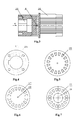
- Fig. 1 is an overall view showing a structure of the disclosed shaft rotating double-stator multi-speed motor with curves of constant width according to example 1.
- the motor comprises a rotor 5, an inner stator 19, an outer stator 3, sets of sliders 22, a left end cover 6 and a right end cover 1.
- a curve of an external surface of a front portion of the inner stator 19 and a curve of an internal surface curve of the outer stator 3 are two similar elliptic curves which are smooth and closed.
- the rotor 5 is mounted with sets of sliders, each set composed of an inner roller 2, a link 4 and an outer roller 12.
- Four oil distributing ports 20 are opened in the elliptic internal surface of the outer stator 3.
- Four oil distributing ports 24 are opened in the elliptic external surface of the front portion of the inner stator 19 which is mounted in the rotor 5.
- An external surface of a rear portion of the inner stator 19 is a cylindrical surface, on which a keyway is machined to cooperate with a keyway in a shaft hole of the right end cover 1 to prevent a relative rotation therebetween.
- a left washer 11 which is a circular member, is mounted on the bottom of the sectorial cylinders 26 of the rotor 5, having sectorial holes 27 on its circumference for fitting sectorial cylinders 26 of the rotor 5, and an oil leakage hole 29 at its center.
- a right washer 13 is also a circular member, having sectorial holes 27 on its circumference for fitting the sectorial cylinders of the rotor 5, and an inner stator mounting hole 28 at its center to engage with a cylindrical surface of the inner stator 19.
- the right washer 13 and an adjusting retaining ring 14 are mounted at the tail of the sectorial cylinders of the rotor 5 to support the rotor.
- the two washers may be provided or not provided depending on the actual machining accuracy of the sectorial cylinders. In case the machining accuracy of the sectorial cylinders of the rotor is high, both of the two washers may be omitted.
- the rotor 5 is mounted in a cavity of the outer stator 3 by means of a left bearing 9 and a right bearing 16.
- the left end cover 6 and the right end cover 1 are mounted on two end faces of the outer stator 3 by fastening bolts 15.
- the left end cover 6 and the right end cover 1 preferably have a circular periphery, while the outer stator 3 preferably has a slightly square cross section.
- the distance between adjacent edges of two adjacent oil distributing ports in outer stator 20 is larger than or equal to the minimum distance between two tangent lines formed by contacting two adjacent sets of sliders 22 with the internal surface of the outer stator 3, so as to ensure that the adjacent oil distributing ports in outer stator 20 are separated from each other by a set of sliders 22.
- the oil distributing ports in outer stator 20 are connected to a hydraulic power unit through oil passing holes in outer stator 21 and a pipeline.
- the distance between adjacent edges of two adjacent oil distributing ports in inner stator 24 is larger than or equal to the minimum distance between two tangent lines formed by contacting two adjacent sets of sliders 22 mounted in the sectorial cylinders 26 of the rotor 5 with the external surface of the front portion of the inner stator 19, so as to ensure that the adjacent oil distributing ports in inner stator 24 are separated from each other by a set of sliders 22.
- the oil distributing ports in inner stator 24 are connected to the hydraulic power unit through oil passing holes in inner stator 23 and a pipeline.
- a screw thread is machined at the tail of the inner stator 19 to axially fix the inner stator 19 by being engaged with a round nut 18.
- a mounting hole 25 for a transmission shaft 7 is formed at a front end of the rotor 5.
- the rotor 5 and the transmission shaft 7 are separate parts.
- the torque and the speed of the rotor 5 are transmitted via the transmission shaft 7.
- a transmission shaft of an actuator or a prime mover may be directly coupled with the rotor mounting hole 25 by a key, thereby omitting the transmission shaft and simplifying the structure of the motor.
- a rear portion of the rotor 5 is machined with a plurality of uniformly distributed sectorial cylinders 26 for mounting the set of sliders 22.
- the sectorial cylinders 26 are obtained by machining the cylindrical rear portion of the rotor, and the distance between two sectorial cylinders 26 is equal to the width of each set of sliders. In this example, there are eight sectorial cylinders 26. To be noted, the width of the sectorial cylinders 26 depends on their eccentric distance and determines the flow rate and the rotary speed. During the implementation, the distance between two sectorial cylinders varies in the set of sliders of different type.
- An oil leakage hole 8 is machined at the center of the rotor 5, and connected to a leakage oil return port 10 of the motor.
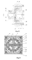
- Fig. 12 illustrates a cantilever-type shaft rotating double-stator multi-speed motor with curves of constant width, comprising a rotor 5, an inner stator 19, an outer stator 3, sets of sliders 22, a left end cover 6 and a right end cover 1, wherein an output shaft and the rotor are provided in a form of a shaft-integrated rotor 31, which is mounted in a shaft hole of the left end cover 6 by a centripetal thrust bearing 9, so that the right washer and the right bearing can be omitted.
- the left end cover 6, the outer stator 3 and the right end cover 1 are fastened by fastening bolts 30.
- the structures of other portions of the motor are the same as those in Example 1, and herein are not repeated.
- the portions of the same function shall be represented with the same reference numeral, but a person skilled in the art may make an appropriate change or selection based on the prior art.
- an inner motor is constructed by the inner stator 19, the inside of a sectorial cylinders 26 of the rotor, the sets of sliders 22 and the end covers at both sides
- an outer motor is constructed by the outer stator 3, the outside of the sectorial cylinders 26 of the rotor, the sets of sliders 22 and the end covers at both sides.
- a differential motor is formed when the torque corresponding to the inner and outer motors are in opposite directions.
- One differential motor is formed in case of single-action, and different combinations can be formed in case of double-action and multi-action to form multiple types of differential motors. Therefore, several different speeds can be implemented within one motor shell.
Landscapes
- Engineering & Computer Science (AREA)
- Mechanical Engineering (AREA)
- General Engineering & Computer Science (AREA)
- Hydraulic Motors (AREA)
- Connection Of Motors, Electrical Generators, Mechanical Devices, And The Like (AREA)
- Rolling Contact Bearings (AREA)
Applications Claiming Priority (2)
| Application Number | Priority Date | Filing Date | Title |
|---|---|---|---|
| CN2010101378298A CN101847917B (zh) | 2010-03-29 | 2010-03-29 | 轴转动等宽曲线双定子多速马达 |
| PCT/CN2011/072216 WO2011120412A1 (fr) | 2010-03-29 | 2011-03-28 | Moteur entraîné par arbre, à double stator, à vitesses multiples, présentant des courbes de même largeur |
Publications (2)
| Publication Number | Publication Date |
|---|---|
| EP2541741A1 true EP2541741A1 (fr) | 2013-01-02 |
| EP2541741A4 EP2541741A4 (fr) | 2016-12-14 |
Family
ID=42772413
Family Applications (1)
| Application Number | Title | Priority Date | Filing Date |
|---|---|---|---|
| EP11761986.6A Withdrawn EP2541741A4 (fr) | 2010-03-29 | 2011-03-28 | Moteur entraîné par arbre, à double stator, à vitesses multiples, présentant des courbes de même largeur |
Country Status (5)
| Country | Link |
|---|---|
| US (1) | US9347317B2 (fr) |
| EP (1) | EP2541741A4 (fr) |
| JP (1) | JP5805747B2 (fr) |
| CN (1) | CN101847917B (fr) |
| WO (1) | WO2011120412A1 (fr) |
Families Citing this family (11)
| Publication number | Priority date | Publication date | Assignee | Title |
|---|---|---|---|---|
| CN101847917B (zh) | 2010-03-29 | 2011-12-21 | 燕山大学 | 轴转动等宽曲线双定子多速马达 |
| CN102720630B (zh) * | 2012-06-08 | 2014-09-24 | 燕山大学 | 双转子壳体转动凸轮连杆滚柱多速马达 |
| CN102691614B (zh) * | 2012-06-08 | 2014-08-13 | 燕山大学 | 双定子摆动液压多速马达 |
| CN102691655B (zh) * | 2012-06-08 | 2015-02-25 | 燕山大学 | 轴转动双定子凸轮转子多输出泵 |
| CN104033329B (zh) * | 2013-03-06 | 2017-04-19 | 宁波高新协力机电液有限公司 | 径向滚柱高速变量油马达 |
| CN104393728B (zh) * | 2014-12-23 | 2017-10-03 | 南车株洲电机有限公司 | 一种双定子电机 |
| US11883942B2 (en) * | 2020-06-24 | 2024-01-30 | Snap-On Incorporated | Flow path diverter for pneumatic tool |
| CN111828310B (zh) * | 2020-07-21 | 2021-06-29 | 安徽理工大学 | 一种具有叶片特征的径向异形柱塞泵及其工作方法 |
| CN112377363A (zh) * | 2020-11-26 | 2021-02-19 | 黄淮学院 | 多级变排量双定子液压马达 |
| CN113565757B (zh) * | 2021-07-01 | 2022-04-19 | 燕山大学 | 一种多级压排多输出泵 |
| CN119878742B (zh) * | 2025-01-14 | 2025-11-18 | 沈阳航空航天大学 | 非圆定宽曲线浮环油膜阻尼器 |
Family Cites Families (21)
| Publication number | Priority date | Publication date | Assignee | Title |
|---|---|---|---|---|
| NL6813309A (fr) * | 1968-09-18 | 1970-03-20 | ||
| US3682143A (en) * | 1970-06-03 | 1972-08-08 | Leas Brothers Dev Corp | Cylindrical rotor internal combustion engine |
| US3761151A (en) * | 1972-08-17 | 1973-09-25 | Nat Res Dev | Thrust bearing |
| GB2016599B (en) * | 1978-03-03 | 1982-07-07 | Trw Inc | Rotary positive-displacement fluid machines |
| JPS5941602A (ja) * | 1982-09-01 | 1984-03-07 | Daikin Ind Ltd | 二重マルチベ−ン型回転機械 |
| US4768936A (en) | 1987-11-27 | 1988-09-06 | Carrier Corporation | Scroll compressor with oil pickup tube in oil sump |
| WO1992003636A1 (fr) * | 1990-08-17 | 1992-03-05 | Norbert Josef Kunta | Systeme hydraulique a pales guidees |
| JP3151551B2 (ja) | 1995-09-13 | 2001-04-03 | 株式会社ベンカン | 管継手 |
| FR2739505B1 (fr) * | 1995-09-29 | 1997-12-19 | Technicatome | Moteur electrique asynchrone discoidal |
| US5855474A (en) * | 1996-01-05 | 1999-01-05 | Shouman; Ahmad R. | Multiple purpose two stage rotating vane device |
| US6684847B1 (en) * | 2002-07-10 | 2004-02-03 | Osama Al-Hawaj | Radial vane rotary device |
| CN1159528C (zh) * | 2002-09-25 | 2004-07-28 | 燕山大学 | 等宽曲线双定子滚柱泵 |
| CN2760280Y (zh) * | 2004-08-26 | 2006-02-22 | 伊顿流体动力(济宁)有限公司 | 双定子叠加式盘配流摆线液压马达 |
| CA2667336A1 (fr) * | 2005-10-26 | 2007-08-09 | Solomon Technologies, Inc. | Systeme de transmission multientrees double sortie a moteur a differentiel electrique |
| CN100438307C (zh) * | 2005-11-18 | 2008-11-26 | 清华大学 | 螺纹驱动多面体超声电机 |
| JP4849328B2 (ja) * | 2006-10-02 | 2012-01-11 | トヨタ車体株式会社 | ダブルステータ型モータ |
| CN100487246C (zh) * | 2007-10-25 | 2009-05-13 | 燕山大学 | 等宽曲线双定子轴向滑块泵 |
| CN201197102Y (zh) * | 2007-12-18 | 2009-02-18 | 苏卫星 | 发电电动多功能一体设备 |
| US20090162225A1 (en) * | 2007-12-20 | 2009-06-25 | Fu Zhun Precision Industry (Shen Zhen) Co., Ltd. | Pump for liquid cooling system |
| CN201282402Y (zh) * | 2008-10-17 | 2009-07-29 | 沈阳工业大学 | 一种多盘式永磁同步电动机 |
| CN101847917B (zh) | 2010-03-29 | 2011-12-21 | 燕山大学 | 轴转动等宽曲线双定子多速马达 |
-
2010
- 2010-03-29 CN CN2010101378298A patent/CN101847917B/zh not_active Expired - Fee Related
-
2011
- 2011-03-28 EP EP11761986.6A patent/EP2541741A4/fr not_active Withdrawn
- 2011-03-28 JP JP2013501609A patent/JP5805747B2/ja not_active Expired - Fee Related
- 2011-03-28 US US13/381,086 patent/US9347317B2/en not_active Expired - Fee Related
- 2011-03-28 WO PCT/CN2011/072216 patent/WO2011120412A1/fr not_active Ceased
Non-Patent Citations (1)
| Title |
|---|
| See references of WO2011120412A1 * |
Also Published As
| Publication number | Publication date |
|---|---|
| JP5805747B2 (ja) | 2015-11-04 |
| CN101847917B (zh) | 2011-12-21 |
| US9347317B2 (en) | 2016-05-24 |
| CN101847917A (zh) | 2010-09-29 |
| US20130039795A1 (en) | 2013-02-14 |
| EP2541741A4 (fr) | 2016-12-14 |
| JP2013527362A (ja) | 2013-06-27 |
| WO2011120412A1 (fr) | 2011-10-06 |
Similar Documents
| Publication | Publication Date | Title |
|---|---|---|
| US9347317B2 (en) | Shaft rotating double-stator multi-speed motor with curves of constant width | |
| JP2009529619A (ja) | アキシャルプランジャーポンプ又はモータ | |
| RU2732083C1 (ru) | Регулировочный блок для регулировки по азимуту и/или для регулировки угла атаки ветроэнергетической установки, соответствующие устройства регулировки с таким регулировочным блоком, ветроэнергетическая установка, способ регулировки роторной лопасти, способ отслеживания направления ветра, а также применение регулировочного блока | |
| US20140271301A1 (en) | Dual Axis Rotor | |
| CN121296532B (zh) | 一种高压大流量旋转配油装置 | |
| US11473575B2 (en) | Dual drive vane pump | |
| EP3070330A1 (fr) | Ensemble bloc de cylindre pour unité hydraulique | |
| US4505185A (en) | Through-shaft energy converter transmission | |
| CN216290426U (zh) | 一种耐磨损节能液压油泵电机组 | |
| EP3048302B1 (fr) | Dispositif de retenue de glissière pour unité hydraulique | |
| US10288156B1 (en) | Transmission assembly | |
| CN213116929U (zh) | 一种精密液压辊、液压电机、低速高扭矩液压系统 | |
| US9435378B1 (en) | Roller bearing outer race for hydraulic unit | |
| US11624363B2 (en) | Dual drive gerotor pump | |
| CN211737217U (zh) | 一种活塞式气动马达曲平块与配气阀芯的新型驱动装置 | |
| US2417816A (en) | Fluid pump or motor | |
| US9845679B2 (en) | Port plate assembly for hydraulic unit | |
| CN212376786U (zh) | 一种轴配流摆线液压马达 | |
| US2129642A (en) | Variable delivery pump or motor | |
| EP3061965B1 (fr) | Bague externe de palier à roulement d'une unité hydraulique | |
| CN110529333B (zh) | 液压马达 | |
| WO2024005650A1 (fr) | Machine tournante | |
| CN102720630B (zh) | 双转子壳体转动凸轮连杆滚柱多速马达 | |
| EP3045720B1 (fr) | Bille de retenue de patin pour unité hydraulique | |
| CN111456982A (zh) | 一种精密液压辊、液压电机、低速高扭矩液压系统 |
Legal Events
| Date | Code | Title | Description |
|---|---|---|---|
| PUAI | Public reference made under article 153(3) epc to a published international application that has entered the european phase |
Free format text: ORIGINAL CODE: 0009012 |
|
| 17P | Request for examination filed |
Effective date: 20111219 |
|
| AK | Designated contracting states |
Kind code of ref document: A1 Designated state(s): AL AT BE BG CH CY CZ DE DK EE ES FI FR GB GR HR HU IE IS IT LI LT LU LV MC MK MT NL NO PL PT RO RS SE SI SK SM TR |
|
| DAX | Request for extension of the european patent (deleted) | ||
| RA4 | Supplementary search report drawn up and despatched (corrected) |
Effective date: 20161110 |
|
| RIC1 | Information provided on ipc code assigned before grant |
Ipc: F04C 2/344 20060101ALI20161104BHEP Ipc: H02K 16/04 20060101AFI20161104BHEP |
|
| STAA | Information on the status of an ep patent application or granted ep patent |
Free format text: STATUS: REQUEST FOR EXAMINATION WAS MADE |
|
| STAA | Information on the status of an ep patent application or granted ep patent |
Free format text: STATUS: THE APPLICATION IS DEEMED TO BE WITHDRAWN |
|
| 18D | Application deemed to be withdrawn |
Effective date: 20170610 |