EP2541744A2 - Moteur linéaire avec culasse magnétique - Google Patents
Moteur linéaire avec culasse magnétique Download PDFInfo
- Publication number
- EP2541744A2 EP2541744A2 EP12173677A EP12173677A EP2541744A2 EP 2541744 A2 EP2541744 A2 EP 2541744A2 EP 12173677 A EP12173677 A EP 12173677A EP 12173677 A EP12173677 A EP 12173677A EP 2541744 A2 EP2541744 A2 EP 2541744A2
- Authority
- EP
- European Patent Office
- Prior art keywords
- linear motor
- back yoke
- shaft
- assembly
- motor according
- Prior art date
- Legal status (The legal status is an assumption and is not a legal conclusion. Google has not performed a legal analysis and makes no representation as to the accuracy of the status listed.)
- Withdrawn
Links
- 230000000712 assembly Effects 0.000 claims abstract description 39
- 238000000429 assembly Methods 0.000 claims abstract description 39
- 230000008878 coupling Effects 0.000 claims description 43
- 238000010168 coupling process Methods 0.000 claims description 43
- 238000005859 coupling reaction Methods 0.000 claims description 43
- 238000004804 winding Methods 0.000 claims description 34
- 230000005284 excitation Effects 0.000 claims description 30
- 230000002093 peripheral effect Effects 0.000 claims description 14
- 238000003825 pressing Methods 0.000 claims description 10
- 239000004020 conductor Substances 0.000 claims description 5
- 239000000696 magnetic material Substances 0.000 claims description 4
- 229910000976 Electrical steel Inorganic materials 0.000 abstract description 2
- 239000000463 material Substances 0.000 abstract description 2
- 239000007769 metal material Substances 0.000 description 6
- XEEYBQQBJWHFJM-UHFFFAOYSA-N Iron Chemical compound [Fe] XEEYBQQBJWHFJM-UHFFFAOYSA-N 0.000 description 4
- 239000000853 adhesive Substances 0.000 description 3
- 230000001070 adhesive effect Effects 0.000 description 3
- 238000003780 insertion Methods 0.000 description 3
- 230000037431 insertion Effects 0.000 description 3
- 238000005192 partition Methods 0.000 description 3
- 239000011810 insulating material Substances 0.000 description 2
- 229910052742 iron Inorganic materials 0.000 description 2
- 239000012778 molding material Substances 0.000 description 2
- 239000004033 plastic Substances 0.000 description 2
- 229920005989 resin Polymers 0.000 description 2
- 239000011347 resin Substances 0.000 description 2
- 239000004593 Epoxy Substances 0.000 description 1
- 229910052782 aluminium Inorganic materials 0.000 description 1
- XAGFODPZIPBFFR-UHFFFAOYSA-N aluminium Chemical compound [Al] XAGFODPZIPBFFR-UHFFFAOYSA-N 0.000 description 1
- 239000003822 epoxy resin Substances 0.000 description 1
- 239000011521 glass Substances 0.000 description 1
- WABPQHHGFIMREM-UHFFFAOYSA-N lead(0) Chemical compound [Pb] WABPQHHGFIMREM-UHFFFAOYSA-N 0.000 description 1
- 238000004519 manufacturing process Methods 0.000 description 1
- 238000012986 modification Methods 0.000 description 1
- 230000004048 modification Effects 0.000 description 1
- 239000003973 paint Substances 0.000 description 1
- 229920000647 polyepoxide Polymers 0.000 description 1
- 238000006748 scratching Methods 0.000 description 1
- 230000002393 scratching effect Effects 0.000 description 1
- 125000006850 spacer group Chemical group 0.000 description 1
Images


Classifications
-
- H—ELECTRICITY
- H02—GENERATION; CONVERSION OR DISTRIBUTION OF ELECTRIC POWER
- H02K—DYNAMO-ELECTRIC MACHINES
- H02K41/00—Propulsion systems in which a rigid body is moved along a path due to dynamo-electric interaction between the body and a magnetic field travelling along the path
- H02K41/02—Linear motors; Sectional motors
- H02K41/03—Synchronous motors; Motors moving step by step; Reluctance motors
- H02K41/031—Synchronous motors; Motors moving step by step; Reluctance motors of the permanent magnet type
-
- H—ELECTRICITY
- H02—GENERATION; CONVERSION OR DISTRIBUTION OF ELECTRIC POWER
- H02K—DYNAMO-ELECTRIC MACHINES
- H02K41/00—Propulsion systems in which a rigid body is moved along a path due to dynamo-electric interaction between the body and a magnetic field travelling along the path
- H02K41/02—Linear motors; Sectional motors
-
- H—ELECTRICITY
- H02—GENERATION; CONVERSION OR DISTRIBUTION OF ELECTRIC POWER
- H02K—DYNAMO-ELECTRIC MACHINES
- H02K1/00—Details of the magnetic circuit
- H02K1/06—Details of the magnetic circuit characterised by the shape, form or construction
- H02K1/12—Stationary parts of the magnetic circuit
-
- H—ELECTRICITY
- H02—GENERATION; CONVERSION OR DISTRIBUTION OF ELECTRIC POWER
- H02K—DYNAMO-ELECTRIC MACHINES
- H02K1/00—Details of the magnetic circuit
- H02K1/06—Details of the magnetic circuit characterised by the shape, form or construction
- H02K1/22—Rotating parts of the magnetic circuit
- H02K1/27—Rotor cores with permanent magnets
-
- H—ELECTRICITY
- H02—GENERATION; CONVERSION OR DISTRIBUTION OF ELECTRIC POWER
- H02K—DYNAMO-ELECTRIC MACHINES
- H02K15/00—Processes or apparatus specially adapted for manufacturing, assembling, maintaining or repairing of dynamo-electric machines
- H02K15/02—Processes or apparatus specially adapted for manufacturing, assembling, maintaining or repairing of dynamo-electric machines of stator or rotor bodies
- H02K15/03—Processes or apparatus specially adapted for manufacturing, assembling, maintaining or repairing of dynamo-electric machines of stator or rotor bodies having permanent magnets
-
- H—ELECTRICITY
- H02—GENERATION; CONVERSION OR DISTRIBUTION OF ELECTRIC POWER
- H02K—DYNAMO-ELECTRIC MACHINES
- H02K2213/00—Specific aspects, not otherwise provided for and not covered by codes H02K2201/00 - H02K2211/00
- H02K2213/03—Machines characterised by numerical values, ranges, mathematical expressions or similar information
-
- H—ELECTRICITY
- H02—GENERATION; CONVERSION OR DISTRIBUTION OF ELECTRIC POWER
- H02K—DYNAMO-ELECTRIC MACHINES
- H02K3/00—Details of windings
- H02K3/46—Fastening of windings on the stator or rotor structure
- H02K3/47—Air-gap windings, i.e. iron-free windings
Definitions
- the present invention relates to a linear motor in which a mover reciprocates with respect to a stator.
- JP 4385406 discloses a linear motor body including a mover and a stator, the mover including a direct drive shaft capable of reciprocating in an axial direction thereof and a permanent magnet array mounted to the direct drive shaft, the stator having a plurality of excitation windings each formed of a winding conductor wound in a coil such that the mover reciprocates in an inner space defined inside the excitation windings.
- a back yoke is disposed outside the stator of the linear motor body to partly form a magnetic circuit of the linear motor body.
- the back yoke is constituted from a pipe made of magnetic material .
- An object of the present invention is to provide a linear motor in which a back yoke can readily be mounted onto a linear motor body.
- Another object of the present invention is to provide a linear motor of which the volume and weight can be reduced.
- a linear motor of the present invention comprises a linear motor body and a back yoke.
- the linear motor body includes a mover including a direct drive shaft capable of reciprocating in an axial direction thereof and a permanent magnet array formed of a plurality of permanent magnets mounted to the direct drive shaft.
- the stator has a plurality of excitation windings disposed along an axial line of the direct drive shaft.
- the excitation windings are each formed of a winding conductor wound in a coil such that the mover reciprocates in an inner space defined inside the excitation windings.
- the back yoke is disposed outside the stator of the linear motor body to partly form a magnetic circuit of the linear motor body.
- the back yoke is constituted from a back yoke assembly made of magnetic material and entirely surrounding the linear motor body.
- the back yoke When the back yoke is constituted from a back yoke assembly including a surrounding portion entirely surrounding the linear motor body as with the present invention, it is easy to mount the back yoke onto the linear motor body simply by assembling the back yoke assembly with the linear motor body.
- the back yoke assembly preferably includes a first divided assembly and a second divided assembly that are combined such that abutting surfaces of the first and second assemblies extend in the axial direction.
- the back yoke assembly may readily be assembled merely by combining the first and second divided assemblies.
- the first and second assemblies preferably have the same dimension and shape.
- a divided assembly of one sort can be used as either of the first and second divided assemblies.
- the first and second divided assemblies may each be formed by press working a magnetic plate. Even if the shapes of the first and second divided assemblies are complicated, the first and second divided assemblies may readily be formed. Since the divided assemblies are each formed by press working a magnetic plate, the linear motor may be downsized in volume and weight.
- lead wires are connected to the excitation windings to supply electric power to the excitation windings.
- At least one of the first and second divided assemblies preferably has a through hole formed for the lead wires to pass therethrough. With this, the lead wires may readily be guided to the outside.
- the through hole may be formed in a slit extending in the axial direction.
- a dimension between the center of the through hole in the axial direction and the center of the first or second assembly in the axial direction is preferably in a range of 1/4 ⁇ p to 1/2 ⁇ p where ⁇ p denotes a pitch of the permanent magnets in the permanent magnet array; and a length of the through hole in the axial direction is preferably in a range of (n-1/2) ⁇ p to (n+1/2) ⁇ p where n stands for a natural number and ⁇ p for a pitch of the permanent magnets in the permanent magnet array.
- the stator may include an insulating pipe inside of which the mover is disposed and on which the excitation windings are mounted.
- a pair of end brackets are fixed at axial ends of the insulating pipe.
- the end brackets each have a bearing fixed therein to support the end of the direct drive shaft movably in the axial direction and unrotatably in a circumferential direction.
- the back yoke assembly is preferably disposed across the pair of end brackets. With this, a plurality of excitation windings may readily be disposed simply by winding a winding conductor around the insulating pipe to form the excitation windings. Further, the back yoke assembly may securely be fixed onto the linear motor body.
- the direct drive shaft may include a cylindrical shaft body housing the permanent magnet array formed of the plurality of permanent magnets that are arranged such that magnetic poles having the same polarity are opposed to each other, and a pair of shaft end members connected to axial ends of the shaft body and supported by the bearings.
- the shaft body and the pair of shaft end members are coupled by coupling pieces; the shaft body is fixedly fitted with an outer peripheral portion of each coupling piece; and the shaft end members are fixedly fitted into an inner peripheral portion of each coupling piece.
- each coupling piece has a smooth surface portion located to the center of the shaft body in a longitudinal direction of the shaft body and a rough surface portion located away from the center of the shaft body in the longitudinal direction. End portions of the shaft body are preferably disposed to be in contact with both of the smooth and rough surface portions. In this manner, the shaft body and the coupling pieces may securely be fixed while maintaining the concentricity of the shaft body and the coupling pieces.
- each coupling piece may have a plurality of concave portions formed therein; and the end portions of the shaft body may have a plurality of convex portions formed therein to be fitted with the concave portions.
- the coupling pieces and the shaft body may tightly be fixed by fitting the convex portions of the shaft body into the concave portions of the coupling pieces.
- the pair of end brackets each include a bracket body portion into which the insulating pipe is inserted and fitted and with which end portions of the back yoke assembly are fitted, and an enlarged portion provided continuously with the bracket body portion and having a larger dimension than the bracket body portion as measured in a direction perpendicular to the axial direction.
- One or more pressing members may be fixedly provided along an outer surface of the first divided assembly and operable to press the first divided assembly onto each end bracket body.
- One or more pressing members may be fixedly provided along an outer surface of the second divided assembly and operable to press the second divided assembly onto each end bracket body.
- the first and second divided assemblies may securely be fixed onto the end bracket bodies by pressing the first and second divided assemblies onto the end bracket bodies with the pressing members. If the first and second divided assemblies are fixed onto the end bracket bodies using an adhesive, the first and second divided assemblies and the end bracket bodies may securely be fixed by means of adhesion.
- Each enlarged portion may have a rectangular outline as viewed in the axial direction.
- pins forming the pressing member may be fixed to four corners of each enlarged portion.
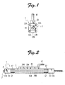
- Figs. 1 to 3 are a front view, a right side view, and a plan view of a linear motor according to an embodiment of the present invention.
- the linear motor of the present invention comprises one linear motor body 3 and a back yoke 5.
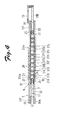
- the linear motor body 3 includes a mover 7 and a stator 9 as shown in Fig. 4.
- Fig. 4 is a cross sectional view of the linear motor body 3, and permanent magnets 21 are depicted in a plane for easy understanding.
- the mover 7 includes a direct drive shaft 11, a permanent magnet array 13, and a linear scale 15.
- the direct drive shaft 11 includes a shaft body 17 and a pair of shaft end members 19A, 19B, and is capable of reciprocating in an axial direction thereof.
- the shaft body 17 is constituted from a cylindrical pipe made of non-magnetic stainless metal material, and houses the permanent magnet array 13 therein.
- Fig. 5 is an enlarged partial view of Fig. 4 .
- Fig. 6 illustrates a coupling piece 25 and a shaft end member 19A of Fig. 5 in a plane.
- the permanent magnet array 13 is formed of a plurality of columnar permanent magnets 21 that are disposed via spacers 23 made of magnetic material such as iron.
- the permanent magnets 21 are arranged in the axial direction such that magnetic poles of two adjacent permanent magnets having the same polarity are opposed to each other.
- the pair of shaft end members 19A, 19B are each shaped in an elongated bar.
- the shaft end members 19A, 19B are connected to axial ends of the shaft body 17 and supported by a pair of bearings 35 slidably in a thrust direction.
- the linear scale 15 is mounted on the shaft end member 19B shown in the right side of Fig. 4 .
- the linear scale 15 is opposed to a linear sensor, not illustrated, disposed outside the linear motor.
- the linear scale 15 and the linear sensor, not illustrated, jointly form a position detecting device to detect a position of the mover 7.
- the linear scale is omitted in Figs. 2 and 3 .
- the pair of shaft end members 19A, 19B are coupled to the shaft body 17 via the coupling pieces 25 as shown in Figs. 5 and 6 .
- the coupling pieces 25 are made of metal material such as iron and stainless metal material.
- the coupling pieces 25 each have a hollow portion 25a inside thereof as shown in Fig. 5 .
- the hollow portion 25a includes a small-diameter portion 25b and two large-diameter portions 25c, 25d having a larger diameter than the small-diameter portion 25b and located on either side of the small-diameter portion 25b.
- a projecting portion 25e extending radially inwardly is formed in the vicinity of the axial center of hollow portion 25a. As shown in Fig.
- an outer peripheral portion 25f of each coupling piece 25 has a smooth surface portion 25g having a smooth surface and located to the center of the shaft body 17 in a longitudinal direction of the shaft body 17 and a rough surface portion 25h having a rough surface and located away from the center of the shaft body 17 in the longitudinal direction.
- the rough surface portion 25h is formed by scratching the surface with a working tool to cause pricks of approximately 0.1 to 0.3 mm in height on the surface.
- End portions of the shaft body 17 are disposed such that inner peripheral surfaces of the end portions of the shaft body 17 are in contact with both of the smooth and rough surface portions 25g, 25h.
- an adhesive is applied to the outer peripheral portion 25f of each coupling piece 25 and then the coupling pieces 25 are pressed into the shaft body 17.
- the shaft body 17 and the coupling pieces 25 are tightly fixed by means of plastic deformation and adhesion.
- the pair of shaft end members 19A, 19B are fixedly fitted into the large-diameter portions 25c of the inner peripheral portions of the coupling pieces 25.
- the shaft end members 19A, 19B each have at ends thereof a hole portion 19c formed with a female screw.
- Amale screw 27 disposed inside the hollow portion 25a of each coupling piece 25 is screwed into the female screw formed in the hole portion 19c.
- the shaft end embers 19A, 19B are tightly fixed to the coupling pieces 25.
- the stator 9 includes an insulating pipe 29, a plurality of excitation windings 31A to 31L, a pair of end brackets 33, and a pair of bearings 35.
- the insulating pipe 29 is made from stainless metal material coated with glass epoxy, insulating paint, or the like.
- the insulating pipe 29 includes a cylindrical body 29a having a thickness of approximately 0.2 mm and thirteen annular partition walls 29b extending radially from the body 29a.
- the excitation windings 31A to 31L are each disposed between two adjacent partition walls 29b.
- the excitation windings 31A to 31L are each formed of a winding conductor wound in a coil around a portion of the body 29a of the insulating pipe 29 between two adjacent partition walls 29b. Three consecutive excitation windings 31A to 31L are grouped as one unit. Excitation currents having three phases shifted by 120° in terms of electrical angle are supplied to the unitized excitation windings. As a result, the excitation currents flow through the excitation windings 31A to 31L in the order of U-phase, V-phase, W-phase, U-phase, V-phase, W-phase, and so on. Lead wires 31m are connected to each of the excitation windings 31A to 31L to supply electric power to the excitation windings 31A to 31L.
- the pair of end brackets 33 are cylindrical in shape and are formed of metal material such as aluminum or workable plastic material.
- Each end bracket 33 has a bracket body portion 33a, and an enlarged portion 33b having a larger dimension than the bracket body portion 33b as measured in a direction perpendicular to the axial direction.
- the bracket body portion 33a has a circular outline as viewed in the axial direction.
- the enlarged portion 33b has a rectangular outline as viewed in the axial direction.
- Four pin insertion holes 33c are formed at four corners of the enlarged portion 33d on the side of the bracket body portion 33a.
- the four tap holes 33h are formed at four corners of the enlarged portion 33b on the opposite side of the bracket body portion 33a.
- the four pin insertion holes 33c are fitted with pins 37 forming a pressing member shown in Figs. 2 and 3 .
- the pins 37 are each made of stainless metal material or the like and are elongated columns in shape. Two of the four pins 37 are disposed along an outer surface of the first divided assembly 39A and are operable to press the first divided assembly 39A onto the bracket body 33a. Likewise, the other two pins 37 are disposed along an outer surface of the second divided assembly 39B and are operable to press the second divided assembly 39B onto the bracket body 33a.
- a female screw is formed in each of the four tap holes 33h, and is used to mount the linear motor 1 onto some external location.
- the end brackets 33 each have a hollow portion 33d inside thereof.
- the hollow portion 33d has a small-diameter portion 33e and first and second large-diameter portions 33f, 33g having a larger diameter than the small-diameter portion 33e.
- the insulating pipe 29 is fixedly fitted into the second large-diameter portion 33g of the end bracket 33.
- the bearing 35 is fixedly fitted into the first large-diameter portion 33f of the end bracket 33.
- the pair of bearings 35 are fixed respectively onto the pair of end brackets 33 to support both ends of the direct drive shaft 11 of the mover 7 slidably in the thrust direction or axial direction and unrotatably in the circumferential direction.
- the linear motor body 3 is housed or wrapped by the back yoke 5.
- the back yoke 5 is disposed outside the stator 9 of the linear motor body 3 to partly form the magnetic circuit of the linear motor body 3.
- the back yoke 5 is constituted from a back yoke assembly including a first divided assembly 39A and a second divided assembly 39B.
- the first and second divided assemblies 39A, 39B have the same dimension and shape, and are formed by press wording a silicon steel plate or SPCC magnetic plate having a thickness of 0.5 to 1.0 mm. Referring to Figs.
- the first and second divided assemblies 39A, 39B are circular in shape as viewed in the axial direction, and each have a through hole 39c formed in the center thereof for the lead wires 31m connected to the excitation windings 31A to 31L to pass therethrough.
- the through hole 39c is formed in a slit located in the middle of the axial line of the direct drive shaft 11 and extending in the axial direction.
- the length of the silt as measured in the axial direction is in a range of (n-1/2) ⁇ p to (n+1/2) ⁇ p where n stands for a natural number and ⁇ p for a pitch of the permanent magnets in the permanent magnet array (See Fig. 4 ).
- the dimension between the center of the through hole 39c in the axial direction and the center of the first or second assembly 39A, 39B in the axial direction is preferably in a range of 1/4 ⁇ p to 1/2 ⁇ p where ⁇ p denotes a pitch of the permanent magnets in the permanent magnet array.
- a bundle 41 of the lead wires 31m connected to the excitation windings 31A to 31L is guided out through one end portion of the through hole 39c as shown in Figs.
- the lead wires 31m and a major part of the through hole 39c are covered by a cover made of an insulating material or resin molding material 43.
- a pair of end portions 39d, 39e of the first divided assembly 39A located in a width direction of the first divided assembly 39A are abutted onto the pair of end portions 39e, 39d of the second divided assembly 39B located in a width direction of the second divided assembly 39B, respectively.
- the first and second divided assemblies 39A, 39B are combined such as the abutting surfaces A extend in the axial direction, and are disposed between the bracket body portions 33a of the pair of end brackets 33 of the linear motor body 3.
- first and second divided assemblies 39A, 39B onto the linear motor body 3.
- an adhesive made of epoxy resin or the like is applied to given positions of the first and second divided assemblies 39A, 39B or the linear motor body 3.
- the first and second divided assemblies 39A, 39B are combined and disposed together on the linear motor body 3.
- a bundle 41 of the lead wires 31m connected to the excitation windings 31A to 31L is guided out from one end portion of the through hole 39c.
- each lead wire 31m and a major part of the through hole 39c are covered by a cover made of an insulating material or a resin molding material 43.
- four pins 37 are inserted into the pin insertion holes 33c formed in four corners of the enlarged portion 33b of each end bracket 33.
- the pins 37 work to press the first and second divided assemblies 39A, 39B onto the bracket body portions 33a.
- the back yoke 5 is constituted from a back yoke assembly (the first and second divided assemblies 39A, 39B) that entirely surrounds or wraps the linear motor body 3.
- the back yoke 5 may readily be mounted onto the linear motor body 3.
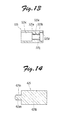
- Fig. 10 is a right side view of a linear motor according to another embodiment of the present invention.
- the linear motor of this embodiment is the same in structure as that shown in Figs. 1 to 9 except a back yoke.
- the counterparts of Fig. 10 except the back yoke are allocated reference numbers defined by adding 100 to those allocated to the parts of Fig. 1 to 9 , and the explanation of such counterparts is omitted.
- a back yoke 105 of this embodiment is also constituted from a back yoke assembly including a first divided assembly 139A and a second divided assembly 139B.
- the first and second divided assemblies 139A, 139B have the same dimension and shape. Referring to Figs.
- the first and second divided assemblies 139A, 139B each have an arc central portion 139f and a pair of flat plate portions 139g disposed at either end of the arc central portion 139f.
- a through hole 139c is formed in the center of the central portion 139f for the lead wires to pass therethrough.
- two convex portions 139h and two concave portions 139i are alternately formed at either ends of each flat plate portion 139 g in a width direction thereof.
- the convex portions 139h are semi-circular in shape.
- the concave portions 139i are semi-circular in shape to allow the convex portions 139h to fit therein. As shown in Fig.
- the convex portions 139h of the first divided assembly 139A are fitted in the concave portions 139i of the second divided assembly 139B, and the convex portions 139h of the second divided assembly 139B are fitted in the concave portions 139i of the first divided assembly 139A when the first and second divided assemblies 139A, 139B are combined such that the abutting surfaces A extend in the axial direction.
- the first and second divided assemblies 139A, 139B may tightly be fixed by accurately positioning the first and second divided assemblies 139A, 139B by means of the fitting of the convex portions 139h and concave portions 139i.
- Figs. 12A to 12C are a front view, a plan view, and a right side view, respectively, of the first and second divided assemblies used in a linear motor according to still another embodiment of the present invention.
- the parts of Figs. 12A to 12C are allocated reference numbers in the 200's.
- the first and second divided assemblies of the linear motor of this embodiment each have a central portion 239f shaped in a rectangular flat plate.
- the dimension of a pair of flat plate portions 239g as measured in a width direction thereof is longer than that of the pair of flat plate portions 139g of the linear motor shown in Figs. 10 and 11 .
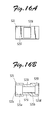
- each coupling piece 325 is formed with a female screw 325j.
- the male screw disposed inside a hollow portion 325a of the coupling piece 325 see the screw 27 in Fig.
- the coupling piece 425 shown in Fig. 14 does not have a hollow portion, and includes a body 425k and a pair of protrusions 425m protruding from the body 425k toward the pair of shaft end members (see the shaft end member 19A in Fig. 5 ).
- a male screw 425n is formed in each protrusion 425m.
- the male screw 425n is screwed into a female screw formed in a hole at an end of each of the pair of shaft end members.
- the pair of shaft end members may be fixed to the coupling pieces 425 without using screws.
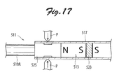
- Fig. 15 is a cross sectional partial view of another mover usable for the linear motor of the present invention.
- the mover of this embodiment is the same in structure as that of the linear motor shown in Figs. 5 and 6 except a shaft body and coupling pieces.
- the counterparts except the shaft body and coupling pieces of this embodiment are allocated reference numbers defined by adding 500 to those of the parts shown in Figs. 5 and 6 , and the explanation of the counterparts is omitted.
- the surface of an outer peripheral portion 525f of each coupling piece 525 is smooth.
- the outer peripheral portion 525f is formed with two rectangular concave portions 525i radially opposed to each other.
- the shaft body 517 is formed with two convex portions 517a to be fitted with the two concave portions 525i of the coupling piece 525.
- the convex portions 517a are formed by press working the shaft body 517 fitted with the coupling piece 525 using a pressing machine P as shown in Fig. 17 .
- the concave portions 525i are fitted with the convex portions 517a, thereby tightly fixing the coupling pieces 525 to the shaft body 517.
- a back yoke is constituted from a back yoke assembly that entirely surrounds or wraps the linear motor body.
- the back yoke may readily be mounted onto a liner motor body simply by combining the back yoke assembly with the linear motor body.
Landscapes
- Engineering & Computer Science (AREA)
- Physics & Mathematics (AREA)
- Chemical & Material Sciences (AREA)
- Combustion & Propulsion (AREA)
- Electromagnetism (AREA)
- Power Engineering (AREA)
- Linear Motors (AREA)
- Iron Core Of Rotating Electric Machines (AREA)
Applications Claiming Priority (1)
| Application Number | Priority Date | Filing Date | Title |
|---|---|---|---|
| JP2011142208A JP5981104B2 (ja) | 2011-06-27 | 2011-06-27 | リニアモータ |
Publications (2)
| Publication Number | Publication Date |
|---|---|
| EP2541744A2 true EP2541744A2 (fr) | 2013-01-02 |
| EP2541744A3 EP2541744A3 (fr) | 2016-07-27 |
Family
ID=46456364
Family Applications (1)
| Application Number | Title | Priority Date | Filing Date |
|---|---|---|---|
| EP12173677.1A Withdrawn EP2541744A3 (fr) | 2011-06-27 | 2012-06-26 | Moteur linéaire avec culasse magnétique |
Country Status (6)
| Country | Link |
|---|---|
| US (1) | US9000627B2 (fr) |
| EP (1) | EP2541744A3 (fr) |
| JP (1) | JP5981104B2 (fr) |
| KR (1) | KR20130001699A (fr) |
| CN (1) | CN102857067B (fr) |
| TW (1) | TWI552491B (fr) |
Cited By (4)
| Publication number | Priority date | Publication date | Assignee | Title |
|---|---|---|---|---|
| EP3065274A4 (fr) * | 2014-03-12 | 2017-07-12 | National Institute of Technology | Moteur linéaire |
| WO2019155022A1 (fr) | 2018-02-09 | 2019-08-15 | Komp-Act Sa | Moteur linéaire |
| WO2020058565A1 (fr) * | 2018-09-21 | 2020-03-26 | Lekatech Oy | Machine électrique linéaire |
| EP4102692A1 (fr) * | 2021-06-11 | 2022-12-14 | Sanyo Denki Co., Ltd. | Moteur linéaire et module de tête linéaire |
Families Citing this family (7)
| Publication number | Priority date | Publication date | Assignee | Title |
|---|---|---|---|---|
| CN104981969B (zh) * | 2013-02-20 | 2016-12-07 | 三菱电机株式会社 | 可动件及具备该可动件的线性电动机 |
| JP6166926B2 (ja) * | 2013-03-26 | 2017-07-19 | 山洋電気株式会社 | リニアモータ |
| JP6082646B2 (ja) | 2013-04-25 | 2017-02-15 | 山洋電気株式会社 | 軸回転型リニアモータ、および軸回転型リニアモータユニット |
| JP2015065746A (ja) * | 2013-09-24 | 2015-04-09 | 山洋電気株式会社 | リニアモータ |
| JP6465282B2 (ja) * | 2014-11-27 | 2019-02-06 | 山洋電気株式会社 | リニアモータ |
| JP2018182863A (ja) * | 2017-04-10 | 2018-11-15 | 三菱電機エンジニアリング株式会社 | リニアモータ及びその固定子の製造方法 |
| TWI629854B (zh) * | 2017-06-03 | 2018-07-11 | Sunonwealth Electric Machine Industry Co., Ltd. | 用於馬達之定子 |
Citations (1)
| Publication number | Priority date | Publication date | Assignee | Title |
|---|---|---|---|---|
| JP4385406B2 (ja) | 2005-10-21 | 2009-12-16 | 株式会社安川電機 | リニアヘッドモジュール |
Family Cites Families (24)
| Publication number | Priority date | Publication date | Assignee | Title |
|---|---|---|---|---|
| JPS5427527Y2 (fr) * | 1974-07-03 | 1979-09-07 | ||
| DE2603680C3 (de) * | 1976-01-31 | 1978-09-28 | Philips Patentverwaltung Gmbh, 2000 Hamburg | Linearmotor, insbesondere für anzeigende und schreibende Meßgeräte |
| JPS5415969Y2 (fr) * | 1977-03-02 | 1979-06-25 | ||
| CA1122638A (fr) * | 1979-03-13 | 1982-04-27 | Cts Corporation | Actionneur electromagnetique lineaire a armature d'aimant permanent |
| US4785816A (en) * | 1985-01-14 | 1988-11-22 | Johnson & Johnson Ultrasound Inc. | Ultrasonic transducer probe assembly |
| CN85200996U (zh) * | 1985-04-01 | 1986-01-15 | 陕西师范大学 | 一种便于装卸的线性管式电动机 |
| US5434549A (en) * | 1992-07-20 | 1995-07-18 | Tdk Corporation | Moving magnet-type actuator |
| JPH07322595A (ja) * | 1994-05-24 | 1995-12-08 | Shicoh Eng Co Ltd | リニア直流モ−タ |
| JP3481759B2 (ja) * | 1995-12-18 | 2003-12-22 | Tdk株式会社 | 永久磁石式リニアモータ |
| JPH11225468A (ja) * | 1998-02-05 | 1999-08-17 | Minolta Co Ltd | シャフト型リニアモータ |
| DE10244261B4 (de) * | 2002-09-24 | 2007-03-29 | Festo Ag & Co. | Spulensystem, insbesondere für einen elektrodynamischen Lineardirektantrieb |
| JP4220880B2 (ja) * | 2003-10-17 | 2009-02-04 | 住友重機械工業株式会社 | 防水型端子台ユニット |
| US7128032B2 (en) * | 2004-03-26 | 2006-10-31 | Bose Corporation | Electromagnetic actuator and control |
| US7378765B2 (en) * | 2004-08-09 | 2008-05-27 | Oriental Motor Co., Ltd. | Cylinder-type linear motor and moving part thereof |
| JP2007043780A (ja) * | 2005-08-01 | 2007-02-15 | Konica Minolta Medical & Graphic Inc | シャフト型リニアモータ及び放射線画像読取装置 |
| US7825548B2 (en) * | 2005-10-21 | 2010-11-02 | Kabushiki Kaisha Yaskawa Denki | Cylindrical linear motor |
| JP4775760B2 (ja) * | 2006-01-13 | 2011-09-21 | 株式会社安川電機 | シリンダ形リニアモータおよびそのガイド装置 |
| JP4756472B2 (ja) * | 2006-05-11 | 2011-08-24 | 株式会社安川電機 | 円筒形リニアモータ界磁部の製造方法および円筒形リニアモータ |
| JP2008086144A (ja) * | 2006-09-28 | 2008-04-10 | Murata Mach Ltd | リニアモータおよびそれを搭載した工作機械 |
| JP2008193760A (ja) * | 2007-01-31 | 2008-08-21 | Tsubakimoto Chain Co | リニアモータ |
| JP5276299B2 (ja) * | 2007-10-19 | 2013-08-28 | 日本トムソン株式会社 | シャフト形リニアモータを内蔵した実装ヘッド |
| US7944096B2 (en) * | 2009-06-05 | 2011-05-17 | Hiwin Mikrosystem Corp. | Stator mechanism of linear motor |
| JP2010288418A (ja) * | 2009-06-15 | 2010-12-24 | Tamagawa Seiki Co Ltd | 円筒型リニアモータ |
| US20110062799A1 (en) * | 2009-09-14 | 2011-03-17 | Chih-Hsien Chao | Stator assembling mechanism of linear motor that is adapted to automated assembling process |
-
2011
- 2011-06-27 JP JP2011142208A patent/JP5981104B2/ja not_active Expired - Fee Related
-
2012
- 2012-06-25 CN CN201210213902.4A patent/CN102857067B/zh not_active Expired - Fee Related
- 2012-06-26 EP EP12173677.1A patent/EP2541744A3/fr not_active Withdrawn
- 2012-06-26 US US13/532,899 patent/US9000627B2/en not_active Expired - Fee Related
- 2012-06-26 KR KR1020120068664A patent/KR20130001699A/ko not_active Withdrawn
- 2012-06-27 TW TW101122995A patent/TWI552491B/zh not_active IP Right Cessation
Patent Citations (1)
| Publication number | Priority date | Publication date | Assignee | Title |
|---|---|---|---|---|
| JP4385406B2 (ja) | 2005-10-21 | 2009-12-16 | 株式会社安川電機 | リニアヘッドモジュール |
Cited By (7)
| Publication number | Priority date | Publication date | Assignee | Title |
|---|---|---|---|---|
| EP3065274A4 (fr) * | 2014-03-12 | 2017-07-12 | National Institute of Technology | Moteur linéaire |
| US10103593B2 (en) | 2014-03-12 | 2018-10-16 | National Institute of Technology | Linear motor |
| WO2019155022A1 (fr) | 2018-02-09 | 2019-08-15 | Komp-Act Sa | Moteur linéaire |
| US11456655B2 (en) | 2018-02-09 | 2022-09-27 | Komp-Act Sa | Linear motor with stacked electromagnets |
| WO2020058565A1 (fr) * | 2018-09-21 | 2020-03-26 | Lekatech Oy | Machine électrique linéaire |
| EP4102692A1 (fr) * | 2021-06-11 | 2022-12-14 | Sanyo Denki Co., Ltd. | Moteur linéaire et module de tête linéaire |
| US12027936B2 (en) | 2021-06-11 | 2024-07-02 | Sanyo Denki Co., Ltd. | Linear motor and linear head module |
Also Published As
| Publication number | Publication date |
|---|---|
| TW201320555A (zh) | 2013-05-16 |
| US20120326533A1 (en) | 2012-12-27 |
| CN102857067B (zh) | 2016-06-15 |
| CN102857067A (zh) | 2013-01-02 |
| JP2013009564A (ja) | 2013-01-10 |
| KR20130001699A (ko) | 2013-01-04 |
| EP2541744A3 (fr) | 2016-07-27 |
| TWI552491B (zh) | 2016-10-01 |
| US9000627B2 (en) | 2015-04-07 |
| JP5981104B2 (ja) | 2016-08-31 |
Similar Documents
| Publication | Publication Date | Title |
|---|---|---|
| EP2541744A2 (fr) | Moteur linéaire avec culasse magnétique | |
| JP6315790B2 (ja) | ブラシレスモータ | |
| JP5814249B2 (ja) | 電動モータ組み立て体 | |
| JP6166926B2 (ja) | リニアモータ | |
| JP6248433B2 (ja) | モータ | |
| WO2013042341A1 (fr) | Moteur et procédé de fabrication du moteur | |
| US8536742B2 (en) | Linear synchronous motor | |
| KR20130032245A (ko) | 고정자 코어 및 고정자 | |
| CN207884413U (zh) | 马达 | |
| JP2021058000A (ja) | モータおよびトランスミッション装置 | |
| US9281734B2 (en) | Linear motor with back yoke | |
| US8487485B2 (en) | Linear synchronous motor | |
| JP2014073030A (ja) | 電機子およびモータ | |
| JP6229331B2 (ja) | モータ | |
| JP2018074638A (ja) | ステータ、モータ、およびステータの製造方法 | |
| JP5254651B2 (ja) | 磁気シールド板付きリニアモータ、磁気シールド板付き多軸リニアモータ、及び磁気シールド板付きリニアモータの製造方法 | |
| JP6330333B2 (ja) | モータ | |
| JP5487020B2 (ja) | 回転電機 | |
| JP2018046651A (ja) | モータおよびモータの製造方法 | |
| US20180301971A1 (en) | Ring-shaped bonded magnet, voice coil motor and method of manufacturing voice coil motor | |
| CN100391087C (zh) | 电动机 | |
| JP6236298B2 (ja) | 可動コイル型リニアモータを内蔵した立軸用スライド装置 | |
| JP2009005562A (ja) | リニアモータ | |
| JP2006087190A (ja) | 非円筒形状のギャップを有するモータ | |
| JP5991841B2 (ja) | 円筒型リニアモータ |
Legal Events
| Date | Code | Title | Description |
|---|---|---|---|
| PUAI | Public reference made under article 153(3) epc to a published international application that has entered the european phase |
Free format text: ORIGINAL CODE: 0009012 |
|
| AK | Designated contracting states |
Kind code of ref document: A2 Designated state(s): AL AT BE BG CH CY CZ DE DK EE ES FI FR GB GR HR HU IE IS IT LI LT LU LV MC MK MT NL NO PL PT RO RS SE SI SK SM TR |
|
| AX | Request for extension of the european patent |
Extension state: BA ME |
|
| PUAL | Search report despatched |
Free format text: ORIGINAL CODE: 0009013 |
|
| AK | Designated contracting states |
Kind code of ref document: A3 Designated state(s): AL AT BE BG CH CY CZ DE DK EE ES FI FR GB GR HR HU IE IS IT LI LT LU LV MC MK MT NL NO PL PT RO RS SE SI SK SM TR |
|
| AX | Request for extension of the european patent |
Extension state: BA ME |
|
| RIC1 | Information provided on ipc code assigned before grant |
Ipc: H02K 1/12 20060101ALN20160617BHEP Ipc: H02K 3/47 20060101ALN20160617BHEP Ipc: H02K 41/03 20060101AFI20160617BHEP |
|
| STAA | Information on the status of an ep patent application or granted ep patent |
Free format text: STATUS: THE APPLICATION HAS BEEN PUBLISHED |
|
| STAA | Information on the status of an ep patent application or granted ep patent |
Free format text: STATUS: THE APPLICATION IS DEEMED TO BE WITHDRAWN |
|
| 18D | Application deemed to be withdrawn |
Effective date: 20170128 |