EP2541751A2 - Dispositif dýexcitation - Google Patents
Dispositif dýexcitation Download PDFInfo
- Publication number
- EP2541751A2 EP2541751A2 EP12172459A EP12172459A EP2541751A2 EP 2541751 A2 EP2541751 A2 EP 2541751A2 EP 12172459 A EP12172459 A EP 12172459A EP 12172459 A EP12172459 A EP 12172459A EP 2541751 A2 EP2541751 A2 EP 2541751A2
- Authority
- EP
- European Patent Office
- Prior art keywords
- excitation
- individual
- excitation device
- windings
- current
- Prior art date
- Legal status (The legal status is an assumption and is not a legal conclusion. Google has not performed a legal analysis and makes no representation as to the accuracy of the status listed.)
- Granted
Links
Images

Classifications
-
- H—ELECTRICITY
- H02—GENERATION; CONVERSION OR DISTRIBUTION OF ELECTRIC POWER
- H02K—DYNAMO-ELECTRIC MACHINES
- H02K3/00—Details of windings
- H02K3/04—Windings characterised by the conductor shape, form or construction, e.g. with bar conductors
-
- H—ELECTRICITY
- H02—GENERATION; CONVERSION OR DISTRIBUTION OF ELECTRIC POWER
- H02K—DYNAMO-ELECTRIC MACHINES
- H02K11/00—Structural association of dynamo-electric machines with electric components or with devices for shielding, monitoring or protection
- H02K11/30—Structural association with control circuits or drive circuits
-
- H—ELECTRICITY
- H02—GENERATION; CONVERSION OR DISTRIBUTION OF ELECTRIC POWER
- H02K—DYNAMO-ELECTRIC MACHINES
- H02K11/00—Structural association of dynamo-electric machines with electric components or with devices for shielding, monitoring or protection
- H02K11/30—Structural association with control circuits or drive circuits
- H02K11/33—Drive circuits, e.g. power electronics
-
- H—ELECTRICITY
- H02—GENERATION; CONVERSION OR DISTRIBUTION OF ELECTRIC POWER
- H02K—DYNAMO-ELECTRIC MACHINES
- H02K19/00—Synchronous motors or generators
- H02K19/16—Synchronous generators
- H02K19/26—Synchronous generators characterised by the arrangement of exciting windings
-
- H—ELECTRICITY
- H02—GENERATION; CONVERSION OR DISTRIBUTION OF ELECTRIC POWER
- H02M—APPARATUS FOR CONVERSION BETWEEN AC AND AC, BETWEEN AC AND DC, OR BETWEEN DC AND DC, AND FOR USE WITH MAINS OR SIMILAR POWER SUPPLY SYSTEMS; CONVERSION OF DC OR AC INPUT POWER INTO SURGE OUTPUT POWER; CONTROL OR REGULATION THEREOF
- H02M7/00—Conversion of AC power input into DC power output; Conversion of DC power input into AC power output
- H02M7/42—Conversion of DC power input into AC power output without possibility of reversal
- H02M7/44—Conversion of DC power input into AC power output without possibility of reversal by static converters
- H02M7/48—Conversion of DC power input into AC power output without possibility of reversal by static converters using discharge tubes with control electrode or semiconductor devices with control electrode
-
- H—ELECTRICITY
- H02—GENERATION; CONVERSION OR DISTRIBUTION OF ELECTRIC POWER
- H02P—CONTROL OR REGULATION OF ELECTRIC MOTORS, ELECTRIC GENERATORS OR DYNAMO-ELECTRIC CONVERTERS; CONTROLLING TRANSFORMERS, REACTORS OR CHOKE COILS
- H02P27/00—Arrangements or methods for the control of AC motors characterised by the kind of supply voltage
- H02P27/04—Arrangements or methods for the control of AC motors characterised by the kind of supply voltage using variable-frequency supply voltage, e.g. inverter or converter supply voltage
- H02P27/06—Arrangements or methods for the control of AC motors characterised by the kind of supply voltage using variable-frequency supply voltage, e.g. inverter or converter supply voltage using DC to AC converters or inverters
- H02P27/08—Arrangements or methods for the control of AC motors characterised by the kind of supply voltage using variable-frequency supply voltage, e.g. inverter or converter supply voltage using DC to AC converters or inverters with pulse width modulation
-
- H—ELECTRICITY
- H02—GENERATION; CONVERSION OR DISTRIBUTION OF ELECTRIC POWER
- H02P—CONTROL OR REGULATION OF ELECTRIC MOTORS, ELECTRIC GENERATORS OR DYNAMO-ELECTRIC CONVERTERS; CONTROLLING TRANSFORMERS, REACTORS OR CHOKE COILS
- H02P25/00—Arrangements or methods for the control of AC motors characterised by the kind of AC motor or by structural details
- H02P25/02—Arrangements or methods for the control of AC motors characterised by the kind of AC motor or by structural details characterised by the kind of motor
- H02P25/08—Reluctance motors
- H02P25/092—Converters specially adapted for controlling reluctance motors
-
- H—ELECTRICITY
- H02—GENERATION; CONVERSION OR DISTRIBUTION OF ELECTRIC POWER
- H02P—CONTROL OR REGULATION OF ELECTRIC MOTORS, ELECTRIC GENERATORS OR DYNAMO-ELECTRIC CONVERTERS; CONTROLLING TRANSFORMERS, REACTORS OR CHOKE COILS
- H02P3/00—Arrangements for stopping or slowing electric motors, generators, or dynamo-electric converters
- H02P3/06—Arrangements for stopping or slowing electric motors, generators, or dynamo-electric converters for stopping or slowing an individual dynamo-electric motor or dynamo-electric converter
- H02P3/18—Arrangements for stopping or slowing electric motors, generators, or dynamo-electric converters for stopping or slowing an individual dynamo-electric motor or dynamo-electric converter for stopping or slowing an AC motor
-
- H—ELECTRICITY
- H02—GENERATION; CONVERSION OR DISTRIBUTION OF ELECTRIC POWER
- H02P—CONTROL OR REGULATION OF ELECTRIC MOTORS, ELECTRIC GENERATORS OR DYNAMO-ELECTRIC CONVERTERS; CONTROLLING TRANSFORMERS, REACTORS OR CHOKE COILS
- H02P9/00—Arrangements for controlling electric generators for the purpose of obtaining a desired output
- H02P9/14—Arrangements for controlling electric generators for the purpose of obtaining a desired output by variation of field
Definitions
- the present invention relates to an excitation device for stators and generators for high-induction measurement according to the pre-characterizing clause of claim 1.
- Excitation devices of this kind are used, for example, in the so-called high-induction testing of stators of large power station generators.
- the stator is excited at mains frequency to a magnetic induction of approximately 1.5 Tesla.
- FIG. 1 A conventional device is shown in Fig. 1 .
- the figure shows the annular stator of a hydrogenerator in schematic form. The rotor is removed for this test. The windings of an excitation coil are arranged around this stator ring. For large stator diameters, individual coil segments are typically distributed symmetrically along the stator circumference for this purpose.
- the excitation coil is operated with alternating voltage at mains frequency.
- considerable voltages and currents and a large inductive reactive power are required in order to achieve the required nominal induction of 1.5 Tesla.
- the electrical energy source (mains connection or generator) is often unable to supply this high unbalanced load.
- the high voltages used are basically hazardous to life, which means a significant outlay for safety measures. For these reasons, the measurement is very laborious. However, it is a compulsory requirement by many customers, especially in the acceptance testing of new generators after fabrication.
- a further solution consists in using an electronic power converter for supplying the excitation winding.
- the reactive power requirement of the excitation coil can be compensated by means of a suitably sized link circuit for the supply of energy.
- the invention is intended to redress this situation.
- the invention as is characterized in the claims, is based on the object of proposing an improved device for the excitation which requires little reactive power from the energy source, which manages with lower supply voltages and supply currents, which produces lower voltages and currents at the outputs and is therefore less dangerous, and which is flexible in application, i.e. suitable for a multiplicity of load cases.
- the device according to the invention provides a cost-effective, flexible and far less dangerous excitation device for stators of generators for high-induction measurement, and also substantially compensates the reactive power requirement.
- the solution of the problem according to the invention is achieved by the use of a modular design of the overall excitation system.
- a number of individual excitation modules hereinafter also referred to as individual modules for short, are used together with a corresponding number of individual excitation windings, which in totality supply the necessary excitation current by superimposing the individual currents.
- Each of the individual modules supplies part of the total excitation current required via its own excitation winding, which consists of a number of dedicated excitation turns.
- the current feeds to the individual modules are controlled and synchronized with one another so that the required total current flows with the required time characteristic by superimposing the individual currents.
- the individual single modules are each equipped with individual energy-supplying electrical link circuits so that the individual modules mainly draw only active power from the supplying energy source.
- the individual excitation coils of the individual modules are electrically connected or isolated from one another in such a way that no excessively high voltages can occur between the windings.
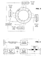
- Fig. 1 shows a conventional device. This figure therefore in particular shows the annular stator of a hydrogenerator in schematic form. The rotor is removed for this test. The windings of an excitation coil are arranged around this stator ring. For large stator diameters, individual coil segments are typically distributed symmetrically along the stator circumference for this purpose.
- the excitation coil is operated with alternating voltage at mains frequency.
- considerable voltages and currents and a large inductive reactive power are required in order to achieve the required nominal induction of 1.5 Tesla.
- Figure 2 shows an excitation device which consists of 4 individual single excitation modules. All individual modules are supplied from the same 400Vrms energy source. The individual modules generate the electrical currents i 1 , i 2 , i 3 , i 4 , which flow through the associated individual excitation windings. The total excitation current is given by superimposing the individual currents.
- the individual excitation windings themselves are not electrically connected to one another. However, there can be an electrical connection of the individual windings via the electronics of the excitation modules or via their connections to the common energy source. However, this connection is devised in such a way that there is no electrical series connection of the individual windings, so that the individual winding voltages do not add together and therefore no excessively high voltages can occur between the windings. The use of heavy medium-voltage cables is therefore unnecessary.
- the individual excitation devices have an output current controller. They therefore act as current sources and supply the required output current regardless of the load situations occurring at any one time. This is important to enforce a uniform current distribution of the total excitation current between the modules. Without an effective current controller, the output currents would be highly dependent on the different impedances of the individual windings, the different voltage levels of the link circuits, the different switch characteristics, etc.
- the individual modules advantageously have an output filter which to some extent dynamically isolates the current control circuit of the individual module from the overall excitation circuit.
- this filter comprises at least a series inductor in the output circuit or, in an improved embodiment, R, L, C filters with series arrangements of inductors and parallel arrangements of capacitors.
- a monitoring circuit which feeds back the load conditions, typically the voltage across the respective individual excitation coils which is driven by the individual excitation module, to the individual controller, can be arranged for improved control.
- Each of the individual modules has its own energy store, which in each case can absorb part of the total reactive energy which occurs when the laminated core is excited.
- an individual module can drive a plurality of individual excitation windings via individual current controllers in each case, wherein a common intermediate energy store is used.
- the current setpoints of the individual excitation modules are typically obtained from a central control module which outputs a sinusoidal current setpoint, for example, to the individual modules.
- a central control module which outputs a sinusoidal current setpoint, for example, to the individual modules.
- all sub-modules have the same current demand.
- the central control module can be connected to sensors, by means of which the magnetic state of the laminated core can be measured, e.g. the magnetic flux in the stator core.
- the individual modules can also be designed so that they themselves generate an alternating current with specified frequency and specifiable time characteristics or amplitude.
- a simple time synchronization device which effects a synchronous current output of the individual modules, is sufficient.
- this requires that the phase angle of the current output of the individual modules can be manipulated.
- the individual excitation module according to Fig. 3 typically consists of the following function blocks which can be seen qualitatively from Fig. 4 :
- This function block is used for storing the reactive energy which occurs transiently. Typically, the energy is stored in capacitors.
- the output DC/AC converter this converts the direct voltage of the link circuit into an alternating quantity, typically an output voltage.
- the time characteristic of this alternating quantity can be manipulated by means of a control input.
- the current controller controls the output converter in such a way that the required output current i(t) is generated in the form of a control variable according to the applied setpoint.
- the setpoint is fed in via an appropriate input.
- the output filter this can optionally be arranged to dynamically decouple the control variable i(t) to a certain extent from the voltage which appears across the excitation coil, and thus ease the control task.
- FIG. 4 Another version of the individual module is shown in Figure 4 .
- This variant can drive 2 excitation coils independently of one another, wherein, however, only a single intermediate energy store and a single input converter are used.
- Output converter, controller and filter are duplicated. The number of these output blocks can be increased so that further coils can be operated independently of one another.
- This variant can advantageously be used when a large-scale distribution of the excitation coils is not required.
- This version is therefore intrinsically well suited for a turbogenerator.
- the use of a plurality of these multiple output modules can also provide advantages for large-scale distributed arrangements, as it is possible to work with further reduced supply voltages and winding voltages.
- the individual converter has a galvanically isolated input stage (galvanically isolated AC/DC input converter) and one or more output stages which act in a switchable manner as controllable, regulated current sources or controllable, regulated voltage sources. This enables a current source output to be connected in series with one or more voltage source outputs in order to achieve higher voltage levels.
- the devices are distinguished as follows:
- Each of the sub-modules is designed as a complete converter which converts the input voltage, has a link circuit for energy storage, and supplies the required output current.
- the sub-modules act as current sources which supply the partial excitation current regardless of the load voltage occurring at any one time.
- the time characteristic of the output current of the sub-module is controlled via a control input.
- the current outputs of the sub-modules of the excitation device are controlled so that the required total excitation current flows.
- the output stages of the individual module can act as current sources and also, alternatively, as voltage sources, wherein the method of operation can be selected by means of a switch.
- the outputs are galvanically isolated from ground and from the voltage inputs.
- the device can also be used for other excitation tasks.
Landscapes
- Engineering & Computer Science (AREA)
- Power Engineering (AREA)
- Microelectronics & Electronic Packaging (AREA)
- Ac-Ac Conversion (AREA)
- Control Of Eletrric Generators (AREA)
Priority Applications (1)
| Application Number | Priority Date | Filing Date | Title |
|---|---|---|---|
| EP12172459.5A EP2541751B1 (fr) | 2011-06-29 | 2012-06-18 | Dispositif d'excitation |
Applications Claiming Priority (2)
| Application Number | Priority Date | Filing Date | Title |
|---|---|---|---|
| EP11171988 | 2011-06-29 | ||
| EP12172459.5A EP2541751B1 (fr) | 2011-06-29 | 2012-06-18 | Dispositif d'excitation |
Publications (3)
| Publication Number | Publication Date |
|---|---|
| EP2541751A2 true EP2541751A2 (fr) | 2013-01-02 |
| EP2541751A3 EP2541751A3 (fr) | 2017-10-25 |
| EP2541751B1 EP2541751B1 (fr) | 2021-08-04 |
Family
ID=46229383
Family Applications (1)
| Application Number | Title | Priority Date | Filing Date |
|---|---|---|---|
| EP12172459.5A Active EP2541751B1 (fr) | 2011-06-29 | 2012-06-18 | Dispositif d'excitation |
Country Status (2)
| Country | Link |
|---|---|
| US (1) | US9293955B2 (fr) |
| EP (1) | EP2541751B1 (fr) |
Cited By (2)
| Publication number | Priority date | Publication date | Assignee | Title |
|---|---|---|---|---|
| EP2806544A1 (fr) | 2013-05-24 | 2014-11-26 | Alstom Technology Ltd | Système d'excitation modulaire |
| EP3106890A1 (fr) * | 2015-06-19 | 2016-12-21 | General Electric Technology GmbH | Procede de mesure d'un noyau de stator d'une machine electrique et dispositif de mesure |
Families Citing this family (2)
| Publication number | Priority date | Publication date | Assignee | Title |
|---|---|---|---|---|
| EP2541751B1 (fr) * | 2011-06-29 | 2021-08-04 | General Electric Technology GmbH | Dispositif d'excitation |
| US20170011418A1 (en) * | 2015-05-29 | 2017-01-12 | Claude Denton | System and method for account ingestion |
Family Cites Families (16)
| Publication number | Priority date | Publication date | Assignee | Title |
|---|---|---|---|---|
| CA1167147A (fr) | 1981-09-02 | 1984-05-08 | Thomas M. Jahns | Systeme propulseur d'embarcation |
| SE437590B (sv) * | 1982-10-01 | 1985-03-04 | Electrolux Ab | Reluktansmotor |
| DE3789046D1 (de) * | 1986-11-04 | 1994-03-24 | Bosch Gmbh Robert | Elektrischer Servoantrieb. |
| US5304883A (en) * | 1992-09-03 | 1994-04-19 | Alliedsignal Inc | Ring wound stator having variable cross section conductors |
| US5786673A (en) * | 1995-09-06 | 1998-07-28 | Johnson Consulting, Inc. | Electric motor |
| AU1092799A (en) * | 1997-10-16 | 1999-05-03 | Steven L. Sullivan | Generators and transformers with toroidally wound stator winding |
| JP3579272B2 (ja) * | 1998-12-10 | 2004-10-20 | ミネベア株式会社 | トロイダルコア型アクチュエータ |
| WO2001080399A1 (fr) * | 2000-04-19 | 2001-10-25 | Wellington Drive Technologies Limited | Procede de fabrication d'enroulements de stator |
| US6469469B1 (en) * | 2000-09-01 | 2002-10-22 | Spellman High Voltage Electronics Corp. | Variable output induction motor drive system |
| US7339287B2 (en) * | 2002-06-23 | 2008-03-04 | Powerlynx A/S | Power converter |
| US6847224B2 (en) * | 2002-10-15 | 2005-01-25 | General Electric Company | Test probe |
| US7049786B1 (en) * | 2002-11-25 | 2006-05-23 | The Texas A&M University System | Unipolar drive topology for permanent magnet brushless DC motors and switched reluctance motors |
| GB2396491B (en) * | 2002-12-21 | 2005-11-30 | Dyson Ltd | Power conversion apparatus |
| US7375499B2 (en) * | 2005-01-14 | 2008-05-20 | Hamilton Sundstrand Corporation | Fault tolerant synchronisation source for excitation control of a three phase power generating system |
| CN101248570A (zh) * | 2006-09-14 | 2008-08-20 | 冈本范政 | 发电机 |
| EP2541751B1 (fr) * | 2011-06-29 | 2021-08-04 | General Electric Technology GmbH | Dispositif d'excitation |
-
2012
- 2012-06-18 EP EP12172459.5A patent/EP2541751B1/fr active Active
- 2012-06-28 US US13/535,742 patent/US9293955B2/en active Active
Non-Patent Citations (1)
| Title |
|---|
| None |
Cited By (5)
| Publication number | Priority date | Publication date | Assignee | Title |
|---|---|---|---|---|
| EP2806544A1 (fr) | 2013-05-24 | 2014-11-26 | Alstom Technology Ltd | Système d'excitation modulaire |
| US9488684B2 (en) | 2013-05-24 | 2016-11-08 | General Electric Technology Gmbh | Modular excitation system |
| CN104181465B (zh) * | 2013-05-24 | 2017-08-22 | 通用电器技术有限公司 | 模块化励磁系统 |
| EP3106890A1 (fr) * | 2015-06-19 | 2016-12-21 | General Electric Technology GmbH | Procede de mesure d'un noyau de stator d'une machine electrique et dispositif de mesure |
| US10458949B2 (en) | 2015-06-19 | 2019-10-29 | General Electric Technology Gmbh | Method for measuring a stator core of an electric machine and measuring device |
Also Published As
| Publication number | Publication date |
|---|---|
| EP2541751A3 (fr) | 2017-10-25 |
| US20130033238A1 (en) | 2013-02-07 |
| US9293955B2 (en) | 2016-03-22 |
| EP2541751B1 (fr) | 2021-08-04 |
Similar Documents
| Publication | Publication Date | Title |
|---|---|---|
| US8097970B2 (en) | Method and arrangement in wind power plant | |
| EP2164159B1 (fr) | Filtre harmonique à basse tension pour systèmes de convertisseur à pleine échelle | |
| US11329544B2 (en) | Filter arrangement | |
| US8964423B2 (en) | Low weight 3-phase 5-output wire power conversion system for micro-grid | |
| CN208094255U (zh) | 用于给车辆供电的功率转换器装置和包括该装置的设备 | |
| EP2520543A1 (fr) | Générateur dýozone | |
| US9293955B2 (en) | Excitation device | |
| EP2850622B1 (fr) | Arrangement à inducteur intégral | |
| US12094635B2 (en) | Inductor assembly | |
| US9488684B2 (en) | Modular excitation system | |
| US20130323136A1 (en) | Power supply arrangement with an inverter for producing a single-phase alternating current | |
| US8847559B1 (en) | Generator system and method of operation | |
| US12374487B2 (en) | Current transformer with current branches on primary conductor | |
| Tzvetkova et al. | Harmonics of voltage and current in an electric power supply system for vertical cement mill | |
| RU2642488C1 (ru) | Система возбуждения асинхронизированной электрической машины | |
| EP2824819B1 (fr) | Redresseur à 12 impulsions avec des condensateurs entrés pour améliorer le facteur de puissance | |
| CN108432106B (zh) | 功率转换系统 | |
| US20180375331A9 (en) | Controlling voltage in electrical power distribution grid | |
| Furmanczyk et al. | Powering 270 V DC Equipment from 230 V AC Aircraft Bus | |
| Buckle et al. | A rotating magnetic field approach to a low distortion poly-phase power rectifier | |
| HK1149380A1 (en) | Ac induction motor | |
| HK1149380B (en) | Ac induction motor |
Legal Events
| Date | Code | Title | Description |
|---|---|---|---|
| PUAI | Public reference made under article 153(3) epc to a published international application that has entered the european phase |
Free format text: ORIGINAL CODE: 0009012 |
|
| AK | Designated contracting states |
Kind code of ref document: A2 Designated state(s): AL AT BE BG CH CY CZ DE DK EE ES FI FR GB GR HR HU IE IS IT LI LT LU LV MC MK MT NL NO PL PT RO RS SE SI SK SM TR |
|
| AX | Request for extension of the european patent |
Extension state: BA ME |
|
| RAP1 | Party data changed (applicant data changed or rights of an application transferred) |
Owner name: GENERAL ELECTRIC TECHNOLOGY GMBH |
|
| PUAL | Search report despatched |
Free format text: ORIGINAL CODE: 0009013 |
|
| AK | Designated contracting states |
Kind code of ref document: A3 Designated state(s): AL AT BE BG CH CY CZ DE DK EE ES FI FR GB GR HR HU IE IS IT LI LT LU LV MC MK MT NL NO PL PT RO RS SE SI SK SM TR |
|
| AX | Request for extension of the european patent |
Extension state: BA ME |
|
| RIC1 | Information provided on ipc code assigned before grant |
Ipc: H02P 27/08 20060101ALI20170915BHEP Ipc: H02P 27/06 20060101ALI20170915BHEP Ipc: H02M 7/48 20070101AFI20170915BHEP Ipc: H02K 29/00 20060101ALI20170915BHEP |
|
| STAA | Information on the status of an ep patent application or granted ep patent |
Free format text: STATUS: REQUEST FOR EXAMINATION WAS MADE |
|
| 17P | Request for examination filed |
Effective date: 20180425 |
|
| RBV | Designated contracting states (corrected) |
Designated state(s): AL AT BE BG CH CY CZ DE DK EE ES FI FR GB GR HR HU IE IS IT LI LT LU LV MC MK MT NL NO PL PT RO RS SE SI SK SM TR |
|
| GRAP | Despatch of communication of intention to grant a patent |
Free format text: ORIGINAL CODE: EPIDOSNIGR1 |
|
| STAA | Information on the status of an ep patent application or granted ep patent |
Free format text: STATUS: GRANT OF PATENT IS INTENDED |
|
| INTG | Intention to grant announced |
Effective date: 20200723 |
|
| GRAJ | Information related to disapproval of communication of intention to grant by the applicant or resumption of examination proceedings by the epo deleted |
Free format text: ORIGINAL CODE: EPIDOSDIGR1 |
|
| STAA | Information on the status of an ep patent application or granted ep patent |
Free format text: STATUS: REQUEST FOR EXAMINATION WAS MADE |
|
| INTC | Intention to grant announced (deleted) | ||
| GRAP | Despatch of communication of intention to grant a patent |
Free format text: ORIGINAL CODE: EPIDOSNIGR1 |
|
| STAA | Information on the status of an ep patent application or granted ep patent |
Free format text: STATUS: GRANT OF PATENT IS INTENDED |
|
| INTG | Intention to grant announced |
Effective date: 20210112 |
|
| GRAS | Grant fee paid |
Free format text: ORIGINAL CODE: EPIDOSNIGR3 |
|
| GRAA | (expected) grant |
Free format text: ORIGINAL CODE: 0009210 |
|
| STAA | Information on the status of an ep patent application or granted ep patent |
Free format text: STATUS: THE PATENT HAS BEEN GRANTED |
|
| AK | Designated contracting states |
Kind code of ref document: B1 Designated state(s): AL AT BE BG CH CY CZ DE DK EE ES FI FR GB GR HR HU IE IS IT LI LT LU LV MC MK MT NL NO PL PT RO RS SE SI SK SM TR |
|
| REG | Reference to a national code |
Ref country code: GB Ref legal event code: FG4D |
|
| REG | Reference to a national code |
Ref country code: AT Ref legal event code: REF Ref document number: 1418026 Country of ref document: AT Kind code of ref document: T Effective date: 20210815 |
|
| REG | Reference to a national code |
Ref country code: CH Ref legal event code: EP |
|
| REG | Reference to a national code |
Ref country code: DE Ref legal event code: R096 Ref document number: 602012076275 Country of ref document: DE |
|
| REG | Reference to a national code |
Ref country code: IE Ref legal event code: FG4D |
|
| REG | Reference to a national code |
Ref country code: LT Ref legal event code: MG9D |
|
| REG | Reference to a national code |
Ref country code: NL Ref legal event code: MP Effective date: 20210804 |
|
| PG25 | Lapsed in a contracting state [announced via postgrant information from national office to epo] |
Ref country code: NO Free format text: LAPSE BECAUSE OF FAILURE TO SUBMIT A TRANSLATION OF THE DESCRIPTION OR TO PAY THE FEE WITHIN THE PRESCRIBED TIME-LIMIT Effective date: 20211104 Ref country code: PT Free format text: LAPSE BECAUSE OF FAILURE TO SUBMIT A TRANSLATION OF THE DESCRIPTION OR TO PAY THE FEE WITHIN THE PRESCRIBED TIME-LIMIT Effective date: 20211206 Ref country code: RS Free format text: LAPSE BECAUSE OF FAILURE TO SUBMIT A TRANSLATION OF THE DESCRIPTION OR TO PAY THE FEE WITHIN THE PRESCRIBED TIME-LIMIT Effective date: 20210804 Ref country code: ES Free format text: LAPSE BECAUSE OF FAILURE TO SUBMIT A TRANSLATION OF THE DESCRIPTION OR TO PAY THE FEE WITHIN THE PRESCRIBED TIME-LIMIT Effective date: 20210804 Ref country code: FI Free format text: LAPSE BECAUSE OF FAILURE TO SUBMIT A TRANSLATION OF THE DESCRIPTION OR TO PAY THE FEE WITHIN THE PRESCRIBED TIME-LIMIT Effective date: 20210804 Ref country code: LT Free format text: LAPSE BECAUSE OF FAILURE TO SUBMIT A TRANSLATION OF THE DESCRIPTION OR TO PAY THE FEE WITHIN THE PRESCRIBED TIME-LIMIT Effective date: 20210804 Ref country code: BG Free format text: LAPSE BECAUSE OF FAILURE TO SUBMIT A TRANSLATION OF THE DESCRIPTION OR TO PAY THE FEE WITHIN THE PRESCRIBED TIME-LIMIT Effective date: 20211104 Ref country code: HR Free format text: LAPSE BECAUSE OF FAILURE TO SUBMIT A TRANSLATION OF THE DESCRIPTION OR TO PAY THE FEE WITHIN THE PRESCRIBED TIME-LIMIT Effective date: 20210804 Ref country code: SE Free format text: LAPSE BECAUSE OF FAILURE TO SUBMIT A TRANSLATION OF THE DESCRIPTION OR TO PAY THE FEE WITHIN THE PRESCRIBED TIME-LIMIT Effective date: 20210804 |
|
| PG25 | Lapsed in a contracting state [announced via postgrant information from national office to epo] |
Ref country code: PL Free format text: LAPSE BECAUSE OF FAILURE TO SUBMIT A TRANSLATION OF THE DESCRIPTION OR TO PAY THE FEE WITHIN THE PRESCRIBED TIME-LIMIT Effective date: 20210804 Ref country code: LV Free format text: LAPSE BECAUSE OF FAILURE TO SUBMIT A TRANSLATION OF THE DESCRIPTION OR TO PAY THE FEE WITHIN THE PRESCRIBED TIME-LIMIT Effective date: 20210804 Ref country code: GR Free format text: LAPSE BECAUSE OF FAILURE TO SUBMIT A TRANSLATION OF THE DESCRIPTION OR TO PAY THE FEE WITHIN THE PRESCRIBED TIME-LIMIT Effective date: 20211105 |
|
| PG25 | Lapsed in a contracting state [announced via postgrant information from national office to epo] |
Ref country code: NL Free format text: LAPSE BECAUSE OF FAILURE TO SUBMIT A TRANSLATION OF THE DESCRIPTION OR TO PAY THE FEE WITHIN THE PRESCRIBED TIME-LIMIT Effective date: 20210804 |
|
| PG25 | Lapsed in a contracting state [announced via postgrant information from national office to epo] |
Ref country code: DK Free format text: LAPSE BECAUSE OF FAILURE TO SUBMIT A TRANSLATION OF THE DESCRIPTION OR TO PAY THE FEE WITHIN THE PRESCRIBED TIME-LIMIT Effective date: 20210804 |
|
| REG | Reference to a national code |
Ref country code: DE Ref legal event code: R097 Ref document number: 602012076275 Country of ref document: DE |
|
| PG25 | Lapsed in a contracting state [announced via postgrant information from national office to epo] |
Ref country code: SM Free format text: LAPSE BECAUSE OF FAILURE TO SUBMIT A TRANSLATION OF THE DESCRIPTION OR TO PAY THE FEE WITHIN THE PRESCRIBED TIME-LIMIT Effective date: 20210804 Ref country code: SK Free format text: LAPSE BECAUSE OF FAILURE TO SUBMIT A TRANSLATION OF THE DESCRIPTION OR TO PAY THE FEE WITHIN THE PRESCRIBED TIME-LIMIT Effective date: 20210804 Ref country code: RO Free format text: LAPSE BECAUSE OF FAILURE TO SUBMIT A TRANSLATION OF THE DESCRIPTION OR TO PAY THE FEE WITHIN THE PRESCRIBED TIME-LIMIT Effective date: 20210804 Ref country code: EE Free format text: LAPSE BECAUSE OF FAILURE TO SUBMIT A TRANSLATION OF THE DESCRIPTION OR TO PAY THE FEE WITHIN THE PRESCRIBED TIME-LIMIT Effective date: 20210804 Ref country code: CZ Free format text: LAPSE BECAUSE OF FAILURE TO SUBMIT A TRANSLATION OF THE DESCRIPTION OR TO PAY THE FEE WITHIN THE PRESCRIBED TIME-LIMIT Effective date: 20210804 Ref country code: AL Free format text: LAPSE BECAUSE OF FAILURE TO SUBMIT A TRANSLATION OF THE DESCRIPTION OR TO PAY THE FEE WITHIN THE PRESCRIBED TIME-LIMIT Effective date: 20210804 |
|
| PLBE | No opposition filed within time limit |
Free format text: ORIGINAL CODE: 0009261 |
|
| STAA | Information on the status of an ep patent application or granted ep patent |
Free format text: STATUS: NO OPPOSITION FILED WITHIN TIME LIMIT |
|
| 26N | No opposition filed |
Effective date: 20220506 |
|
| PG25 | Lapsed in a contracting state [announced via postgrant information from national office to epo] |
Ref country code: IT Free format text: LAPSE BECAUSE OF FAILURE TO SUBMIT A TRANSLATION OF THE DESCRIPTION OR TO PAY THE FEE WITHIN THE PRESCRIBED TIME-LIMIT Effective date: 20210804 |
|
| PG25 | Lapsed in a contracting state [announced via postgrant information from national office to epo] |
Ref country code: SI Free format text: LAPSE BECAUSE OF FAILURE TO SUBMIT A TRANSLATION OF THE DESCRIPTION OR TO PAY THE FEE WITHIN THE PRESCRIBED TIME-LIMIT Effective date: 20210804 |
|
| PG25 | Lapsed in a contracting state [announced via postgrant information from national office to epo] |
Ref country code: MC Free format text: LAPSE BECAUSE OF FAILURE TO SUBMIT A TRANSLATION OF THE DESCRIPTION OR TO PAY THE FEE WITHIN THE PRESCRIBED TIME-LIMIT Effective date: 20210804 |
|
| REG | Reference to a national code |
Ref country code: BE Ref legal event code: MM Effective date: 20220630 |
|
| GBPC | Gb: european patent ceased through non-payment of renewal fee |
Effective date: 20220618 |
|
| PG25 | Lapsed in a contracting state [announced via postgrant information from national office to epo] |
Ref country code: LU Free format text: LAPSE BECAUSE OF NON-PAYMENT OF DUE FEES Effective date: 20220618 Ref country code: IE Free format text: LAPSE BECAUSE OF NON-PAYMENT OF DUE FEES Effective date: 20220618 Ref country code: FR Free format text: LAPSE BECAUSE OF NON-PAYMENT OF DUE FEES Effective date: 20220630 |
|
| PG25 | Lapsed in a contracting state [announced via postgrant information from national office to epo] |
Ref country code: GB Free format text: LAPSE BECAUSE OF NON-PAYMENT OF DUE FEES Effective date: 20220618 Ref country code: BE Free format text: LAPSE BECAUSE OF NON-PAYMENT OF DUE FEES Effective date: 20220630 |
|
| P01 | Opt-out of the competence of the unified patent court (upc) registered |
Effective date: 20230522 |
|
| REG | Reference to a national code |
Ref country code: AT Ref legal event code: UEP Ref document number: 1418026 Country of ref document: AT Kind code of ref document: T Effective date: 20210804 |
|
| PG25 | Lapsed in a contracting state [announced via postgrant information from national office to epo] |
Ref country code: HU Free format text: LAPSE BECAUSE OF FAILURE TO SUBMIT A TRANSLATION OF THE DESCRIPTION OR TO PAY THE FEE WITHIN THE PRESCRIBED TIME-LIMIT; INVALID AB INITIO Effective date: 20120618 |
|
| PG25 | Lapsed in a contracting state [announced via postgrant information from national office to epo] |
Ref country code: MK Free format text: LAPSE BECAUSE OF FAILURE TO SUBMIT A TRANSLATION OF THE DESCRIPTION OR TO PAY THE FEE WITHIN THE PRESCRIBED TIME-LIMIT Effective date: 20210804 Ref country code: CY Free format text: LAPSE BECAUSE OF FAILURE TO SUBMIT A TRANSLATION OF THE DESCRIPTION OR TO PAY THE FEE WITHIN THE PRESCRIBED TIME-LIMIT Effective date: 20210804 |
|
| PG25 | Lapsed in a contracting state [announced via postgrant information from national office to epo] |
Ref country code: TR Free format text: LAPSE BECAUSE OF FAILURE TO SUBMIT A TRANSLATION OF THE DESCRIPTION OR TO PAY THE FEE WITHIN THE PRESCRIBED TIME-LIMIT Effective date: 20210804 |
|
| PG25 | Lapsed in a contracting state [announced via postgrant information from national office to epo] |
Ref country code: MT Free format text: LAPSE BECAUSE OF FAILURE TO SUBMIT A TRANSLATION OF THE DESCRIPTION OR TO PAY THE FEE WITHIN THE PRESCRIBED TIME-LIMIT Effective date: 20210804 |
|
| PGFP | Annual fee paid to national office [announced via postgrant information from national office to epo] |
Ref country code: DE Payment date: 20250520 Year of fee payment: 14 |
|
| PGFP | Annual fee paid to national office [announced via postgrant information from national office to epo] |
Ref country code: AT Payment date: 20250522 Year of fee payment: 14 |
|
| PGFP | Annual fee paid to national office [announced via postgrant information from national office to epo] |
Ref country code: CH Payment date: 20250701 Year of fee payment: 14 |