EP2541828A2 - Neue Rahmen- und Signalisierungsmusterstruktur für Mehrträgersysteme - Google Patents
Neue Rahmen- und Signalisierungsmusterstruktur für Mehrträgersysteme Download PDFInfo
- Publication number
- EP2541828A2 EP2541828A2 EP12175157A EP12175157A EP2541828A2 EP 2541828 A2 EP2541828 A2 EP 2541828A2 EP 12175157 A EP12175157 A EP 12175157A EP 12175157 A EP12175157 A EP 12175157A EP 2541828 A2 EP2541828 A2 EP 2541828A2
- Authority
- EP
- European Patent Office
- Prior art keywords
- data
- signalling
- patterns
- frame
- pattern
- Prior art date
- Legal status (The legal status is an assumption and is not a legal conclusion. Google has not performed a legal analysis and makes no representation as to the accuracy of the status listed.)
- Granted
Links
Images













Classifications
-
- H—ELECTRICITY
- H04—ELECTRIC COMMUNICATION TECHNIQUE
- H04L—TRANSMISSION OF DIGITAL INFORMATION, e.g. TELEGRAPHIC COMMUNICATION
- H04L27/00—Modulated-carrier systems
- H04L27/26—Systems using multi-frequency codes
- H04L27/2601—Multicarrier modulation systems
- H04L27/2602—Signal structure
- H04L27/261—Details of reference signals
- H04L27/2613—Structure of the reference signals
-
- H—ELECTRICITY
- H04—ELECTRIC COMMUNICATION TECHNIQUE
- H04L—TRANSMISSION OF DIGITAL INFORMATION, e.g. TELEGRAPHIC COMMUNICATION
- H04L27/00—Modulated-carrier systems
- H04L27/26—Systems using multi-frequency codes
- H04L27/2601—Multicarrier modulation systems
- H04L27/2626—Arrangements specific to the transmitter only
-
- H—ELECTRICITY
- H04—ELECTRIC COMMUNICATION TECHNIQUE
- H04L—TRANSMISSION OF DIGITAL INFORMATION, e.g. TELEGRAPHIC COMMUNICATION
- H04L5/00—Arrangements affording multiple use of the transmission path
- H04L5/0001—Arrangements for dividing the transmission path
- H04L5/0003—Two-dimensional division
- H04L5/0005—Time-frequency
- H04L5/0007—Time-frequency the frequencies being orthogonal, e.g. OFDM(A) or DMT
-
- H—ELECTRICITY
- H04—ELECTRIC COMMUNICATION TECHNIQUE
- H04L—TRANSMISSION OF DIGITAL INFORMATION, e.g. TELEGRAPHIC COMMUNICATION
- H04L5/00—Arrangements affording multiple use of the transmission path
- H04L5/003—Arrangements for allocating sub-channels of the transmission path
- H04L5/0048—Allocation of pilot signals, i.e. of signals known to the receiver
- H04L5/005—Allocation of pilot signals, i.e. of signals known to the receiver of common pilots, i.e. pilots destined for multiple users or terminals
-
- H—ELECTRICITY
- H04—ELECTRIC COMMUNICATION TECHNIQUE
- H04L—TRANSMISSION OF DIGITAL INFORMATION, e.g. TELEGRAPHIC COMMUNICATION
- H04L25/00—Baseband systems
- H04L25/02—Details ; arrangements for supplying electrical power along data transmission lines
- H04L25/0202—Channel estimation
- H04L25/0224—Channel estimation using sounding signals
-
- H—ELECTRICITY
- H04—ELECTRIC COMMUNICATION TECHNIQUE
- H04L—TRANSMISSION OF DIGITAL INFORMATION, e.g. TELEGRAPHIC COMMUNICATION
- H04L27/00—Modulated-carrier systems
- H04L27/26—Systems using multi-frequency codes
- H04L27/2601—Multicarrier modulation systems
- H04L27/2602—Signal structure
- H04L27/261—Details of reference signals
- H04L27/2613—Structure of the reference signals
- H04L27/26132—Structure of the reference signals using repetition
-
- H—ELECTRICITY
- H04—ELECTRIC COMMUNICATION TECHNIQUE
- H04L—TRANSMISSION OF DIGITAL INFORMATION, e.g. TELEGRAPHIC COMMUNICATION
- H04L27/00—Modulated-carrier systems
- H04L27/26—Systems using multi-frequency codes
- H04L27/2601—Multicarrier modulation systems
- H04L27/2602—Signal structure
- H04L27/261—Details of reference signals
- H04L27/2613—Structure of the reference signals
- H04L27/26136—Pilot sequence conveying additional information
Definitions
- the present invention is directed to a new frame and signalling pattern structure for multi-carrier systems.
- the present invention is hereby mainly directed (but not limited) to broadcast systems, such as for example cable based or terrestrial digital broadcast systems, in which content data, signalling data, pilot signals and so forth are mapped on to a plurality of frequency carriers, which are then transmitted in a given overall or complete transmission bandwidth.
- the receiver typically tunes to a partial channel (part of the overall transmission bandwidth) out of the complete transmission bandwidth (sometimes called segmented reception) in order to receive only the content data which is necessary or wanted by the respective receiver.
- the overall channel bandwidth is hereby divided into 13 fixed segments of an equal length (equal number of frequency carriers).
- the object of the present invention is therefore to provide a transmission apparatus and method as well as a signal structure for a multi-carrier system, which allows a receiver to be flexibly tuned to any required part of the overall transmission bandwidth.
- the transmitting apparatus is adapted to transmit signals in a multi-carrier system on the basis of a frame structure, each frame comprising at least two signalling patterns adjacent to each other in the frequency direction and at least two data patterns, said transmitting apparatus comprising signalling mapping means adapted to map signalling data on frequency carriers of each of said at least two signalling patterns in a frame, each signalling pattern having the same length, data mapping means adapted to map data on frequency carriers of said at least two data patterns in a frame, transforming means adapted to transform said signalling patterns and said data patterns from the frequency domain into the time domain in order to generate a time domain transmission signal, and transmitting means adapted to transmit said time domain transmission signal.
- the transmitting method according to the present invention is adapted to transmit signals in a multi-carrier system on the basis of a frame structure each frame comprising at least two signalling patterns adjacent to each other in the frequency direction and at least two data patterns, whereby the method comprises the steps of mapping signalling data on frequency carriers of each of said at least two signalling patterns in a frame, each signalling pattern having the same length, mapping data on frequency carriers of said at least two data patterns in a frame, transforming said signalling patterns and said data patterns from the frequency domain into the time domain in order to generate a time domain transmission signal, and transmitting said time domain transmission signal.
- the above object is further achieved by a frame pattern according to claim 25.
- the frame pattern of the present invention is adapted for a multi-carrier system and comprises at least two signalling patterns adjacent to each other in the frequency direction and at least two data patterns, wherein signalling data are mapped on frequency carriers of each of said at least two signalling patterns in the frame, each signalling pattern having the same length, and wherein data are mapped on frequency carriers of said at least two data patterns in the frame.
- each frame comprises at least two signalling patterns, which respectively carry signalling data or information on frequency carriers and respectively have the same length (or bandwidth).
- each frame After a conversion into the time domain, in the resulting time domain signal, each frame then comprises a respective signalling symbol as well as data symbols.
- Each frame pattern covers the entire or overall transmission bandwidth in the frequency direction, so that the overall transmission bandwidth is therefore equally divided by the signalling patterns having the same respective length.
- the data patterns of each frame then follow the signalling patterns in time.
- the receiving apparatus can be freely and flexibly tuned to any wanted part of the transmission bandwidth, provided that the part of the transmission bandwidth to which the receiving apparatus can be tuned has at least the length of one of the signalling patterns.
- the receiving apparatus is always able to receive the signalling data of an entire signalling pattern, so that on the basis and using the signalling data comprising the physical layer information necessary for the receipt of the succeeding data patterns, the data patterns can be received in the receiving apparatus.
- each frame comprises at least two additional signalling patterns succeeding said at least two signalling patterns in the time dimension, each of said additional signalling patterns having the respective same length as the corresponding one of said at least two preceding signalling patterns.
- each frame comprises at least two training patterns, wherein pilot signals are mapped on frequency carriers of each training pattern in a frame, and wherein the signalling patterns are aligned to the training patterns in the frequency direction.
- the receiving apparatus which first receives the training pattern is able to perform time, synchronisation, frequency offset calculation and/or channel estimation, where after the signalling data in the received signalling patterns can be received and used to receive the succeeding data patterns independent of the tuning position of the receiving apparatus.
- every training pattern has the same length, and the length of each signalling pattern is the same as the length of each of said training patterns.
- every training pattern has the same length, and the length of each signalling pattern is smaller than the length of each of said training patterns.
- the length of each signalling pattern may be half the length of each of said training patterns. Implementations may be possible in which the signalling patterns are not aligned with the training patterns.
- each signalling pattern comprises at least one guard band.
- each signalling pattern may comprise a guard band at its beginning and a guard band at its end.
- each signalling pattern of each frame comprises the location of the signalling pattern within the frame, which is extracted and evaluated on the receiving side.
- each signalling pattern in each frame could comprise the identical signalling data except the location of the respective signalling pattern in the frame, which is different in at least some of the signalling patterns in a frame.
- the receiving apparatus is able to determine its position within the overall transmission bandwidth (within each frame) for example during the initialisation period, in which the receiving apparatus is tuned to an arbitrary position within a frame, and then to tune to the bandwidth enabling the receipt of the wanted data on the basis of the signalling data in the received signalling pattern.
- the signalling patterns of each frame comprise signalling data indicating the number of data patterns comprised in the frame. Further advantageously, the structure of the signalling data in the signalling patterns supports a limited maximum number of data patterns in the frequency direction of each frame. Further, the signalling patterns of each frame may comprise individual signalling data for each data pattern comprised in the frame.
- the signalling data of the signalling patterns comprise an error detection and/or correction coding.
- each frame comprises additional data patterns succeeding said at least two data patterns in the time dimension, each of said additional data patterns having the respective same length as the corresponding one of said previous at least two data patterns.
- the structure of the data patterns in each frame is advantageously set up in a way that at least two data patterns are arranged next to each other in the frequency dimension so that the entire transmission bandwidth is covered.
- Additional data patterns are then arranged in the same frame but following the at least two data patterns in the time direction, whereby each additional or following data pattern has the same length (in the frequency dimension or direction) as the previous data pattern in the same frequency position.
- each additional or following data pattern has the same length (in the frequency dimension or direction) as the previous data pattern in the same frequency position.
- the multi-carrier system with the frame structure as suggested by the present invention thus enables a very flexible transmission of data content in which the length of data patterns, and thus the amount of data per data pattern can be dynamically changed, for example from frame to frame or in any other required way.
- the length and/or the number of the data patterns may be fixed or permanent.
- the present invention can be applied to any kind of multi-carrier system in which a transmitting apparatus is adapted to transmit data in an entire transmission bandwidth and a receiving apparatus is adapted to selectively receive only a part of said entire transmission bandwidth.
- Non limiting examples for such systems may be existing or future uni-directional or bi-directional broadcast systems, such as wired or wireless (for example cable based, terrestrial etc.) digital video broadcast systems.
- the non limiting example for a multi-carrier system would be an orthogonal frequency division multiplex (OFDM) system, however, any other suitable system could be used in which signalling data, pilot signals and other kind of data are mapped on a plurality of frequency carriers.
- OFDM orthogonal frequency division multiplex
- the frequency carriers may hereby be equidistant and respectively have the same length (bandwidth).
- the present invention may also be used in multi-carrier systems in which the frequency carriers are not equidistant and/or do not have the respectively same length.
- the present invention is not limited to any kind of specific frequency range neither in the overall transmission bandwidth applied on the transmitting side nor on the selected part of the transmission bandwidth to which the receiving side is tuned.
- a receiving bandwidth on the receiving side i.e. a bandwidth for the part of the transmission bandwidth to which the receiver can be tuned, which corresponds to the bandwidth of receiving devices of existing (digital video broadcast or other) systems.
- a non limiting example for a receiver bandwidth may be 8 MHz, i.e. the receiving side can be tuned to any wanted 8 MHz bandwidth from the overall transmission bandwidth.
- the overall transmission bandwidth could be a multiple of 8 MHz, for example 8 MHz, 16 MHz, 24 MHz, 32 MHz etc, so that the segmentation of the overall transmission bandwidth, i.e. length of each training pattern could be 8 MHz.
- other segmentations are possible, e.g. (but not limited to) a length of each training pattern of 6 MHz.
- the length of each of the signalling patterns used in the frame structure of the present invention could be 8 MHz, 4MHz (or less).
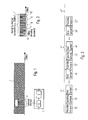
- Fig. 1 shows a schematic representation of an entire transmission bandwidth 1, in which a transmitting apparatus according to the present invention, as for example the transmitting apparatus 54 schematically shown in Fig. 17 , transmits signals in a multi-carrier system in line with the present invention.
- Fig. 1 further schematically shows a block diagram of a receiving apparatus 3 of the present invention, which is adapted to be tuned to and selectively receive a selected part 2 of the transmission bandwidth 1.
- the receiving apparatus 3 comprises a tuner 4 which is adapted to be tuned to and selectively receive the wanted part 2 of the transmission bandwidth 1 as well as further processing means 5 which perform the further necessary processing of the received signals in line with the respective communication system, such as a demodulation, channel decoding and the like.
- FIG. 18 shows a receiving apparatus 63 comprising a receiving interface 64, which can for example be an antenna, an antenna pattern, a wired or cable-based receiving interface or any other suitable interface adapted to receive signals in the respective transmission system or communication system.
- the receiving interface 64 of the receiving apparatus 63 is connected to a receiving means 65 which comprises a tuning means, such as the tuning means 4 shown in Fig. 1 as well as further necessary processing elements depending on the respective transmission or communication system, such as down conversion means adapted to down convert the received signal to an intermediate frequency or the base band.
- Fig. 2 shows a schematic representation of an overall transmission bandwidth 1, within which a transmitting apparatus 54 of the present invention is adapted to transmit data content, such as video data, audio data or any other kind of data, in different segments or parts 6, 7, 8, 9 and 10.
- data content such as video data, audio data or any other kind of data
- the parts 6, 7, 8, 9 and 10 could be used by the transmitting apparatus 54 to transmit different kinds of data, data from different sources, data intended for different recipients and so forth.
- the parts 6 and 9 have for example a maximum bandwidth, i.e. the maximum bandwidth which can be received by a corresponding receiving apparatus 63.
- the parts 7, 8 and 10 have smaller bandwidths.
- the present invention now suggests to apply a frame structure or pattern to the entire transmission bandwidth 1 whereby each frame comprises at least two training patterns adjacent to each other in the frequency direction and a number of data patterns.
- Each training pattern of a frame will have the same length and the identical pilot signals.
- the overall transmission bandwidth 1 is divided into equal parts for the training patterns, whereby the maximum bandwidth to which a receiver can be tuned, for example the bandwidth shown for parts 6 and 9 in Fig. 2 , has to be equal or larger than the length of each training pattern.
- a receiving apparatus 63 according to the present invention can correctly synchronize to the transmitting apparatus 54 and tune to and receive the wanted data in a flexible and non limiting way.
- a frequency offset calculation and/or a channel estimation is/are possible in the receiving apparatus 63 on the basis of such a received training pattern. It is further clear that the length of the various data parts in the transmission bandwidth cannot exceed the length (number of frequency carriers) of the training patterns in the respective frame as will be explained in more detail further below.
- Fig. 3 shows a schematic representation of a time domain structure of frames 11, 11', 11" according to the present invention.
- Each frame 11, 11', 11" comprises a preamble symbol (or training symbol) 12, 12', 12", one or more signalling symbols 13, 13'and several data symbols 14, 14'.
- the preamble symbols or training symbols are preceding the signalling symbols which are preceding the data symbols.
- Each frame 11, 11', 11" may have a plurality of data symbols, wherein systems are possible in which the number of data symbols in each frame 11, 11 ⁇ , 11" varies.
- the preamble symbols are used in a receiving apparatus 63 to perform time synchronisation and eventually additional tasks, such as channel estimation and/or frequency offset calculation.
- the signalling symbols 13, 13' contain signalling information, for example all physical layer information that is needed by the receiving apparatus 63 to decode the received signals, such as but not limited to L1 signalling data.
- the signalling data may for example comprise the allocation of data content to the various data patterns, i.e. for example which services, data streams, modulation, error correction settings etc. are located on which frequency carriers, so that the receiving apparatus 63 can obtain information to which part of the entire transmission bandwidth it shall be tuned.
- the signalling symbols may contain signalling data indicating the offset of the respective data pattern from the preamble or training pattern and/or the signalling pattern so that the receiving apparatus 63 may optimize the tuning to the wanted part of the transmission frequency in a way that the receipt of the training patterns and/or the signalling patterns is optimized.
- the use of the frame structure according to the present invention has the further advantage that by dividing the data stream into logical blocks, changes of the frame structure can be signalled from frame to frame, whereby a preceding frame signals the changed frame structure of the or one of the succeeding frames.
- the frame structure allows a seamless change of modulation parameters without creating errors.
- Figures 4A, 4B, 5A and 5B show non limiting examples of preamble structures which could be used in the present invention. It has to be understood, however, that other possible preamble structures could also be used.
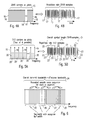
- Fig. 4A shows a frequency domain representation of a preamble or training pattern 15 in which a plurality of frequency carriers 16 (in the shown example 2048 carriers), respectively carry a pilot signal. In other words, all frequency carriers of the training pattern 15 carry a pilot signal.
- Fig. 4B shows the training pattern of Fig. 4A after the transformation in the time domain.
- the time domain training symbol comprises a plurality of time domain samples 17 (in the shown example 2048 samples) in a single repetition. In other words, the time domain training symbol does not have any repetitions in the time domain samples.
- Fig. 5A shows a further non limiting example of a frequency domain preamble pattern 18, comprising a plurality of frequency carriers (in the shown example 512 carriers).
- a frequency domain preamble pattern comprising a plurality of frequency carriers (in the shown example 512 carriers).
- the time domain preamble or the training symbol 21 shown in Fig. 5B shows four repetitions 22, each repetition 22 having the identical samples 23 (same value and number).
- the time domain training symbol has a length of 2048 time samples and each repetition 22 comprises 512 samples.
- the general rule is that the number of repetitions in the time domain corresponds to the repetition rate of the pilot signals in the frequency domain.
- the time domain symbol thus comprises four shortened training symbols.
- pseudo noise pilot signal sequences in order to obtain pseudo noise like signal patterns in the time domain.
- CAZAC constant amplitude zero auto correlation
- Such sequences allow a time synchronisation in a receiving apparatus 63 of the present invention.
- sequences allow a reliable channel estimation in the receiving apparatus 63 in case that the Nyquist criterion is fulfilled in the frequency dimension. Further, such sequences allow a frequency offset calculation and/or a channel estimation in the receiving apparatus 63.
- the present invention suggests a frequency domain frame structure or frame pattern for the entire transmission bandwidth of the transmitting apparatus 54, in which identical training patterns are repeated over the entire transmission bandwidth, i.e. immediately adjacent to each other in the frequency direction.
- Fig. 6 visualizes schematically such a sequence of identical and adjacent training patterns 25, 26, 27, 28 in an entire transmission bandwidth 24.
- the same sequence of pilot signals is mapped onto the frequency carrier of each training pattern 25, 26, 27, 28, so that each training pattern has the same length (or bandwidth) and the same number of frequency carriers (assumed that the frequency sub-carriers are equidistant and respectively have the same length or bandwidth).
- Fig. 6 visualizes schematically such a sequence of identical and adjacent training patterns 25, 26, 27, 28 in an entire transmission bandwidth 24.
- the same sequence of pilot signals is mapped onto the frequency carrier of each training pattern 25, 26, 27, 28, so that each training pattern has the same length (or bandwidth) and the same number of frequency carriers (assumed that the frequency sub-carriers are equidistant and respectively
- the overall transmission bandwidth 24 is equally divided into the training patterns 25, 26, 27, 28 having respectively the same length.
- the length of the training patterns 25, 26, 27 and 28 also corresponds to the minimum tuning bandwidth to which the receiving apparatus 63 of the present invention can be tuned in order to receive signals, in order to ensure that the receiving apparatus 63 is always able to receive an entire training pattern for synchronisation (and channel estimation, and /or frequency offset calculation).
- the present invention therefore enables a receiving apparatus 63 to be tuned to any position within the overall channel bandwidth 24 in a very flexible manner while still being able to perform a reliable synchronisation by correlating the received pilot signals for example in a correlation means 67 of the receiving apparatus 63 as shown in Fig.18 .
- the invention suggests to divide the entire transmission frequency bandwidth 24 into adjacent sub-blocks or segments each having a training pattern containing a repetition of the identical pilot signal sequence and thus having the same length.
- the length of each of the training pattern thus corresponds advantageously to the bandwidth to which the receiving apparatus 63 can be tuned. For example, as shown in Fig.
- the receiving apparatus 63 comprises a receiving interface 64, such as an antenna, a wired receiving interface or the like, to which signals are received in a receiving means 65, which comprises a tuner. If the receiving apparatus 63 is tuned to a part of the transmission bandwidth which matches or coincides to one of the training patterns, the pilot signal sequence is received in the original order. If the receiving apparatus 63 is tuned to an arbitrary part of the transmission bandwidth or for example between two training patterns, still all pilot signals of the training pattern are received, however, not in the original sequence.
- a receiving interface 64 such as an antenna, a wired receiving interface or the like
- the correlation means 67 of the receiving apparatus 63 of the present invention still delivers good results when performing an auto-correlation i.e. a correlation of the received pilot signals with themselves.
- auto-correlation is expected to deliver good results because of the high signal to noise ratio.
- sequences enable a frequency offset calculation and/or a channel estimation in the receiving apparatus 63.
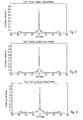
- Fig. 7 shows an example of a simulation result for 64 sample pseudo noise sequence for a multi-carrier system without segmentation of the training pattern, i.e. in which the transmission bandwidth is identical to the receiving bandwidth.
- the correlation peak is clearly visible.
- Fig. 8 shows a further example of a simulation result for a system according to the present invention, in which the entire transmission bandwidth comprises identical training patterns and the receiver is tuned to a part of the transmission bandwidth. In the simulation shown in Fig. 8 , the receiver was tuned and identically matched to the first segment, i.e. the first training pattern of the entire transmission bandwidth. In other words, the simulation shows an auto-correlation result for the situation in which the receiver receives the pilot signals of a training pattern in the original sequence. Again, the correlation peak is clearly visible.
- Fig. 9 now shows a simulation result for the system of Fig. 8 , whereby the receiver was tuned to a position between two training patterns so that the receiver did not receive the pilot signals in the original sequence, but received the last part of a preceding training pattern before the first part of the succeeding training pattern.
- the receiver was tuned to a position between two training patterns so that the receiver did not receive the pilot signals in the original sequence, but received the last part of a preceding training pattern before the first part of the succeeding training pattern.
- an auto-correlation peak which is shown in Fig. 9 .
- an optionally provided rearranging means 66 could rearrange the received pilot signals into the original sequence and to perform a cross-correlation on the basis of a comparison with a stored version of the expected training pattern in order to obtain a cross-correlation result.
- Such a cross-correlation result will normally have a better quality then an auto-correlation result since it is less effected by noise. Thus, for systems with low signal to noise ratios, cross correlation would be the better choice.
- Fig. 10 shows a schematic example of a frequency domain representation of a frame structure or pattern 29 according to the present invention.
- the frame structure 29 covers the entire transmission bandwidth 24 in the frequency direction and comprises at least two training patterns 30 adjacent to each other in the frequency direction, each carrying the identical sequence of pilot signals on respective frequency carriers and having the same length.
- the entire transmission bandwidth 24 is sub-divided into four training patterns 30, but any other higher or lower number of training patterns might be suitable.
- a pilot mapping means 55 is adapted to map the pilot signals onto the frequency carriers of each training pattern.
- a pseudo noise sequence or a CAZAC sequence is used for the pilot signals, but any other sequence with good pseudo noise and/or correlation properties might be suitable.
- the pilot mapping means 55 may be adapted to map a pilot signal onto every frequency carrier in the training patterns, as explained in relation to Fig. 4 .
- the pilot mapping means 55 might be adapted to map a pilot signal onto every m-th frequency carrier (m being a natural number larger than 1) as for example explained in relation to Fig. 5 .
- the length or bandwidth 39 of every training pattern 30 is the same as the bandwidth 38 to which the tuner of the receiving apparatus 63 can be tuned.
- the part of the transmission bandwidth to which the tuner of the receiving apparatus 63 can be tuned may be larger than the length of a training pattern 30.
- the received pilots can further (after transformation into the frequency domain in the transformation means 68) be used for a channel estimation for the frequency carriers in the frame in a channel estimation means 69, which provides a de-mapping means 70 with the necessary channel estimation information enabling a correct de-mapping of the data in the received data signals.
- the received pilots can be used in the receiving apparatus 63 for a frequency offset calculation in a corresponding means which is not shown in Fig. 18 .
- the frame structure or pattern 29 further comprises at least two signalling patterns 31 adjacent to each other in the frequency direction which follow the training patterns 30 in the time direction.
- Each signalling pattern 31 has the same length and bandwidth as the respectively preceding training pattern 30, and the beginning and the end of each signalling pattern 31 in the frequency direction are identical to the beginning and the end of the respective (time wise) preceding training pattern 30, so that the frequency structure of the signalling patterns 31 is identical to the frequency structure of the training patterns 30.
- the signalling patterns 31 are aligned to the training patterns 30.
- the transmitting apparatus 54 of the present invention shown in Fig. 17 comprises a signalling data mapping means 57 which is adapted to map signalling data onto the frequency carriers of each signalling pattern 31.
- each signalling pattern 31 comprises for example the location of the signalling pattern 31 within the frame.
- each signalling pattern 31 in each frame has and carries the identical signalling data, except the location of the respective signalling pattern in the frame, which is different in each signalling pattern 31 in a frame.
- the signalling data are for example L1 signalling data which contain all physical layer information that is needed by the receiving apparatus 63 to decode received signals.
- any other suitable signalling data may be comprised in the signalling patterns 31.
- the signalling patterns 31 might for example comprise the location of the respective data segments 32, 33, 34, 35, 36 so that a receiving apparatus 63 knows where the wanted data segments are located so that the tuner of the receiving apparatus 63 can tune to the respective location in order to receive the wanted data segments.
- the receiving apparatus 63 after the receiving means 65 with the tuner, comprises a transformation means 68 for transforming the received time domain signals into the frequency domain, where after the signalling data (after an optional reconstruction in a reconstruction means 71), are de-mapped in a de-mapping means 72 and then evaluated in an evaluation means 73.
- the evaluation means 73 is adapted to extract the necessary and required signalling information from the received signalling data. If necessary, additional signalling patterns could be provided in the time direction immediately succeeding the signalling patterns 31.
- the frame structure or pattern 29 further comprises at least two data segments extending over the entire frequency bandwidth 24 in the frequency direction and following the signalling patterns 31 in the time direction.
- the frame structure 29 shows several data segments 32, 33, 34, 35, 36 and 37 with different lengths, i.e. a different number of respective frequency carriers onto which data are mapped.
- the frame structure 29 further comprises additional data segments in succeeding time slots, whereby the additional data patterns respectively have the same length and number of frequency carriers as the respectively preceding data pattern.
- the data pattern 32', 32" and 32''' have the same length as the first data pattern 32.
- the data patterns 33', 33" and 33''' have the same length as the data segment 33.
- the additional data patterns have the same frequency dimension structure as the several data patterns 32, 33, 34, 35, 36 and 37 in the first time slot after the signalling patterns 31.
- the receiving apparatus 63 for example tunes to a part 38 of the transmission bandwidth in order to receive the data pattern 35, all time wise succeeding data patterns 35', 35" and 35''' which have the same length as the data pattern 35 can be properly received.
- the flexible and variable data pattern structure of the frame structure or pattern 29 as suggested by the present invention can for example be implemented in the transmitting apparatus 54 of the present invention as shown in Fig. 17 by mapping of various different data streams, for example with different kinds of data and/or data from different sources, as visualized by the branches data 1, data 2 and data 3 in Fig. 17 .
- the respective data are then mapped onto frequency carriers in respective data patterns by the respective data mapping means 58, 58' and 58''.
- at least some of the various data patterns may have different lengths, i.e. different numbers of frequency carriers in case that the frequency carriers are equidistant and have the same bandwidth, respectively.
- the number of data patterns in the frequency direction may be the same as the number of training patterns, wherein the length (or bandwidth) of each data patterns may be identical to the length of each training patterns and they may be aligned to each other (have the same frequency direction structure).
- each data pattern might have the same length and the number of the data patterns might be a multiple of the number of training patterns, while still having the same frequency structure and alignment. Thus for example, 2, 3, 4 or more data patterns would be aligned to each of the training patterns.
- the length of the data patterns needs to be smaller or at maximum equal to the effective receiver bandwidth so that the data patterns can be received in the receiving apparatus 63.
- the transmitting apparatus 54 may be adapted to change the data pattern structure, e.g. the length and/or the number of the data patterns dynamically.
- the structure of the data patterns could be fixed or permanent.
- the data patterns could advantageously comprise pilot signals mapped on some of the frequency carriers in order to enable a fine channel estimation on the receiving side.
- the pilot signal could be scattered among the carriers with the data in a regular or an irregular pattern depending.
- the frequency carriers with the pilots from the pilot mapping means 55, the frequency carriers with the signalling data from the signalling mapping means 57 and the frequency carriers with the data from the various data mapping means 58, 58', 58" are then combined to a frame pattern or structure 29 according to the present invention in a frame forming means 59.
- the frame structure of the present invention could be fixed or permanent, i.e. the overall bandwidth as well as the extension of each frame in the time direction could be fixed and always the same.
- the frame structure can also be flexible, i.e. the overall bandwidth and/or the extension of each frame in the time direction could be flexible and changed from time to time depending on the desired application.
- the number of time slots with data patterns could be flexibly changed.
- the changes could be signalled to a receiving apparatus in the signalling data of the signalling patterns.
- the part 38 to which the receiving apparatus 63 is tuned does not match with the frequency structure of the training patterns 30 and signalling patterns 31.
- the correlation means 67 of the receiving apparatus 63 is still able to perform an auto-(or cross-)correlation.
- the receiving apparatus 63 needs knowledge about the offset of the part 38 in relation to the frequency structure of the frame pattern 29 in order to be able to re-arrange the receive signalling carriers into the original signalling sequence of the signalling patterns 31 which is done in a reconstruction means 71. This is due to the fact that the signalling patterns 31 have the same length and frequency structure as the training patterns 30.
- the receiving apparatus 63 tunes to an arbitrary frequency part of the overall frequency bandwidth.
- the training pattern 30 could for example have a 8 MHz bandwidth.
- the receiving apparatus 63 is able to receive an entire training pattern 30 in the original or re-ordered sequence as well as an entire signalling pattern 31 in the original or re-ordered sequence from the received training pattern 30.
- the receiving apparatus 63 is able to perform a correlation in the correlation means 67 in order to obtain a time synchronisation, as well as perform a channel estimation (usually a coarse channel estimation) in a channel estimation means 69 and/or a frequency offset calculation after a transformation of the received time domain signals into the frequency domain in the transformation means 68.
- the evaluation means 73 of the receiving apparatus 63 the received signalling data are evaluated, for example the location of the received signalling pattern in the frame is obtained so that the receiver can freely and flexibly tune to the respectively wanted frequency position, such as the part 38 is shown in Figure 10 .
- the receiving apparatus 63 In the new tuning position, which will usually not necessarily match with the frequency structure of the training patterns 30 and the signalling patterns 31, the receiving apparatus 63 is still able to perform synchronisation, channel estimation and frequency offset calculation on the basis of the pilot signals of the training patterns 30 due to their cyclic nature.
- the received signalling signals In order to be able to properly evaluate the signalling data of the signalling patterns 31, the received signalling signals have to be re-ordered which is performed in a reconstructing means 71 as described.
- Fig. 11 shows this reordering in a schematic example.
- the last part 31' of a previous signalling pattern is received before the first part 31" of a succeeding signalling pattern, where after the reconstructions means 71 places the part 31' after the part 31" in order to reconstruct the original sequence of the signalling data, where after the reordered signalling pattern is evaluated in the evaluation means 73 after a corresponding de-mapping of the signalling data from the frequency carriers in the demapping means 72. It is to be remembered that the content of each signalling pattern 31 is the same, so that this reordering is possible.
- a receiving apparatus does not provide a flat frequency response over the complete receiving bandwidth to which the receiver is tuned.
- a transmission system usually faces increasing attenuation at the boarder of the receiving bandwidth window.
- Fig. 12 shows a schematic representation of a typical filter shape example. It can be seen that the filter is not rectangular, so that e.g. instead of 8 MHz bandwidth, the receiving apparatus is only able to effectively receive 7.4 MHz bandwidth. The consequence is that the receiving apparatus 63 may not be able to perform the reordering of the signalling data as described in relation to Fig. 11 in case that the signalling patterns 31 have the same length and bandwidth as the receiving bandwidth of the receiving apparatus 63, so that some signals are lost and cannot be received at the border of the receiving bandwidth.
- the present invention alternatively or additionally suggests to use signalling patterns 31a which have a reduced length as compared to the training patterns 30.
- the example shown in Fig. 13 it is suggested to use signalling patterns 31a which have exactly half the length of a training pattern 30, but still the same frequency structure as the training patterns 30. In other words, respective two (i.e. pairs) of the half length signalling patterns 31a are matched and aligned with each one of the training patterns 30 as shown in Fig. 13 .
- each pair of signalling patterns 31a would have the identical signalling data including the location of the signalling patterns 31a in the respective frame.
- the signalling data would be identical except the location information.
- the signalling pattern 31a would then each have a length or bandwidth of 4 MHz.
- the additional signalling patterns 31b have the same time and frequency arrangement/alignment as the signalling patterns 31a, but comprise additional and different signalling information as the signalling information contained in the signalling patterns 31a.
- the receiving apparatus 63 will be able to receive the signalling patterns 31a and 31 b completely and the reconstruction means 71 of the receiving apparatus is adapted to combine the signalling data of the signalling patterns 31a and 31 b to the original sequence.
- the reconstruction means 71 in the receiving apparatus 63 can be omitted. It is also possible to only provide one time slot with half length signalling patterns 31a if all necessary signalling data can be transmitted in the half length and the additional signalling patterns 31b are not necessary.
- the length (or bandwidth) of the training patterns, the data patterns and/or the signalling patterns could be adapted to, e.g. could be smaller than or at maximum equal to, the effective receiving bandwidth of the receiving apparatus 63, for example to the output bandwidth of the receiving band pass filter, as described above.
- the training patterns, the signalling patterns and/or the data patterns of the frame structure described by the present invention could comprise additional guard bands, i.e. unused carriers at the beginning and/or the end of the respective pattern or frame.
- each training pattern could comprise a guard band at the beginning and the end of each pattern.
- the training pattern at position 39 could comprise a guard band only at the beginning of the pattern, and the last training pattern in each frame could comprise a guard band only at the end of the pattern.
- the training pattern at position 39 could comprise a guard band at the beginning as well as at the end of the pattern, and the last training pattern in each frame could comprise a guard band at the beginning as well as at end of the pattern.
- the length of the guard band comprised in some or all of the training patterns could for example be smaller or at maximum equal to the maximum frequency offset the receiving apparatus can cope with.
- the guard band could for example have a length of 250 to 500 kHz or any other suitable length.
- the length of each of the guard bands comprised in the training patterns could be at least the length of the carriers which are not received in the receiving apparatus due to the filter characteristics as described in relation to Fig. 12 .
- the length of each of the guard bands comprised in the training patterns could be at least the length of each of the signalling pattern guard bands.
- each signalling pattern i.e. the signalling patterns 30, 31a and/or 31b, could comprise a guard band with unused carriers at the beginning and the end of each pattern.
- An example for this situation is shown in Fig. 15 , which schematically shows several signalling patterns 31a arranged succeeding each other in the frequency dimension each having a guard band 31a' at its beginning and a further guard band 3 1 a" at its end.
- each signalling pattern has a length of 4 MHz
- a suggestion for the length of each guard band at the beginning and the end of each signalling pattern would be 343 frequency carriers (which is the number of not used carriers in the data patterns at the beginning and end of each frame in each 4nk mode).
- the length of each of the guard bands comprised in the signalling patterns could be at least the length of the carriers which are not received in the receiving apparatus due to the filter characteristics as described in relation to Fig. 12 , so that the length of the signalling data in each signalling pattern is equal to (or may be smaller than) the effective receiver bandwidth.
- additional signalling patterns 31b are present, as explained in relation to Fig. 13 , they will have the same guard bands 31a' and 31a" as the signalling patterns 31a.
- the signalling patterns 30 as described in relation to Fig. 13 could have the guard bands 31a' and 31a" as described.
- each data pattern could comprise a guard band with unused carriers at the beginning and the end of each pattern.
- the data patterns 32, 32', 32", 32''' could comprise a guard band only at the beginning of the data pattern
- the data patterns 37, 37', 37", 37''' could comprise a guard band at the end of the data pattern.
- the length of the guard bands of the data patterns could for example be the same as the length of the guard bands of the signalling patterns if the signalling patterns comprise guard bands, and/or the guard bands of the training patterns if the training patterns comprise guard bands.
- the signalling data comprised in the signalling patterns 31, 31a and or 31 b comprise the physical layer information, which enables a receiving apparatus 63 according to the present invention to obtain knowledge about the frame structure and to receive and decode the wanted data patterns.
- the signalling data could comprise parameters such as the overall or entire transmission bandwidth, the guard band length for the training patterns, the location of the respective signalling pattern within the frame, the guard band length for the signalling patterns, the guard band length for the data patterns, the number of frames which build a super frame, the number of the present frame within a super frame, the number of data patterns in the frequency dimension of the overall frame bandwidth, the number of additional data patterns in the time dimension of a frame and/or individual signalling data for each data pattern in each frame.
- the location of the respective signalling pattern within a frame can e.g. indicate the position of the signalling pattern in relation to the training patterns or in relation to the segmentation of the overall bandwidth. For example, in the case of Fig.
- the signalling data comprise indication if the signalling pattern is located in the first segment (e.g. the first 8 MHz segment), or the second segment etc..
- the signalling patterns having half the length of the training patterns as e.g. explained in relation to Fig. 13
- each pair of adjacent signalling patterns then has the same location information.
- the receiving apparatus will be able to tune to the wanted frequency band in the succeeding frame using this location information.
- the individual signalling data are a separate block of data individually provided for each data pattern present in the frame and may comprise parameters such as the first frequency carrier of the data pattern, the number of frequency carriers allocated to the data pattern, the modulation used for the data pattern, the error protection code used for the data pattern, the usage of a time interleaver for the data pattern, the number of frequency notches (frequency carriers which are not used for data transmission in data pattern) in the data pattern, the position of the frequency notches and/or the width of the frequency notches.
- the signalling mapping means 57 of the transmitting apparatus 54 is adapted to map the corresponding signalling data on the frequency carriers of each signalling pattern.
- the evaluation means 67 of the receiving apparatus 63 is adapted to evaluate the received signalling data and to use or forward the information comprised in the signalling data for further processing within the receiving apparatus 63.
- the structure of the signalling patterns support a maximum limited number of data patterns in the frequency direction per frame in order to restrict the size of each signalling pattern to a maximum size.
- the additional data patterns in the time direction of each frame are respectively aligned with the preceding data patterns, as explained above.
- each additional succeeding data pattern has the same position, length, modulation etc. as the preceding data pattern so that the signalling data for the preceding data pattern are also valid for the succeeding data pattern.
- the number of additional data patterns in the time direction of each frame could be fixed or flexible and this information could also be comprised in the signalling data.
- the structure of the signalling patterns could support only a maximum limited number of frequency notches in each data pattern.
- the transmitting apparatus 54 could optionally comprise an error coding means 56 adapted to add some kind of error coding, redundancy, such as repetition coding, cyclic redundancy coding, or the like to the signalling data which are mapped onto the frequency carriers of a signalling pattern by the signalling mapping means 57.
- the additional error coding would enable the transmitting apparatus 54 to use signalling patterns 31 in the same length as the training patterns 30, as shown in Fig. 10 , since the receiving apparatus 63 is able, for example, by means of the reconstructing means 71, to perform some kind of error detection and/or correction in order to reconstruct the original signalling pattern.
- the following table shows a specific (non-limiting) example of a signalling structure: Table 1: signalling structure n of n4k 4 bits Current n of n4k 4 bits Guard Interval length 2 bits Superframe length 16 bits Frame number 16 bits Number of data patterns 5 bits (or 4 or 6 bits) Loop over data patterns with individual information about each data pattern ⁇ n - Segment number 4 bits Start carrier number 12 bits Data pattern width (number of carriers) 12 bits Data pattern QAM modulation 3 bits LDPC blocksize 1 bit LDPC coderate 3 bits Time interleaver enable 1 bit Number of notches 2 bits Loop over notches ⁇ Start carrier number 12 bits Notch width (number of carriers) 12 bits ⁇ End notch loop PSI/SI reprocessing 1 bit ⁇ End data pattern loop Reserved 1 bit (or 0 or 2 bits) CRC_32 MIP 32 bits
- the frame structure can have a maximum of 32 data patterns per frame in the frequency dimension, so that in a system with an overall bandwidth of 32 MHz (four times the training pattern length of 8 MHz), each data pattern has a minimum length of 1 MHz.
- An appropriate shortened Reed Salomon coding could be applied to the signalling data.
- the encoded data could for example be mapped onto two consecutive QPSK symbols, or any other suitable modulation could be used.
- the frame structure can have a maximum of 64 data patterns per frame in the frequency dimension, so that in a system with an overall bandwidth of 32 MHz (four times the training pattern length of 8 MHz), each data pattern has a minimum length of 0.5 MHz.
- An appropriate shortened Reed Salomon coding could be applied to the signalling data.
- the encoded data could for example be mapped onto two consecutive 16-QAM symbols, or any other suitable modulation could be used.
- the frame structure can have a maximum of 16 data patterns per frame in the frequency dimension, so that in a system with an overall bandwidth of 32 MHz (four times the training pattern length of 8 MHz), each data pattern has a minimum length of 2 MHz.
- An appropriate shortened Reed Salomon coding could be applied to the signalling data.
- the encoded data could for example be mapped onto one QPSK symbol, or any other suitable modulation could be used.
- the present invention further suggests to optimize the tuning position of the receiving apparatus 63.
- the receiver is tuned to a part 38 of the transmission bandwidth by centering the part 38 around the frequency bandwidth of the data patterns to be received.
- the receiving apparatus 63 could be tuned so that the reception of the signalling pattern 31 is optimized by placing the part 38 so that a maximum part of a signalling pattern 31 is received while the wanted data pattern is still fully received.
- the present invention suggests that the length of the respective data patterns should not be different from the length of the respective preamble patterns 30 and signalling patterns 31 by more than a certain percentage for example 10%. An example for this solution can be found in Fig.
- the borders between the data patterns 42, 43, 44 and 45 are (in the frequency direction) not deviating from the borders between preamble patterns 30 and the signalling patterns 31 by more than a certain percentage, such as (but not limited to)10%. This small percentage can then be corrected by the above-mentioned additional error coding in the signalling patterns 31.
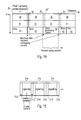
- Fig. 16 shows a time domain representation of an example of frame 47 according to the present invention.
- the frequency domain frame pattern is transformed into the time domain by a transformation means 60.
- An example of a resulting time domain frame is now shown in Fig. 16 .
- the frame 47 comprises a number of shortened training symbols 48, resulting from a mapping of pilot signals only onto every m-th frequency carrier (m being a natural number larger or equal than 2) by a pilot mapping means 55, followed by a guard interval 49, a signalling symbol 50, a further guard interval 51 and a number of data symbols 52, which are respectively separated by guard intervals 53.
- Fig. 13 While the situation that only a single signalling symbol is present in the time domain corresponds to the example shown in Fig. 10 , where only a single time slot with signalling patterns is present in the frequency domain frame structure, the example of Fig. 13 with two time slots with signalling patterns 31a and 31b, respectively, would lead to the presence of two signalling patterns in the time domain, which are eventually separated by a guard interval.
- the guard intervals could e.g. be cyclic extensions of the useful parts of the respective symbols.
- the synchronization reliability could be generally enhanced by inverting the last training symbol, i.e. by inverting the phase of the last training symbol in respect to the preceding training symbols (which have all the same phase).
- the signalling symbols and the data symbols could respectively have the length of one OFDM symbol.
- the time domain frames are then forwarded to a transmission means 61 which processes the time domain signal depending on the used multi-carrier system, for example by up-converting the signal to the wanted transmission frequency.
- the transmission signals are then transmitted via a transmission interface 62, which can be a wired interface or a wireless interface, such as an antenna or the like.
- the number of shortened training symbols 48 in frame 47 is depending on the wanted implementation and the used transmission system. As a non-limiting example, the number of shortened training symbols 48 could be 8, which is a good compromise between correlation complexity and synchronization reliability.
- Fig. 16 further shows that a respective number of frames could be combined to super frames.
- the number of frames per super frame i.e. the length of each super frame in the time direction, could be fixed or could vary.
- the signalling data in the signalling patterns for each frame in a super frame are the same and if changes in the signalling data only occur from super frame to super frame.
- the modulation, coding, number of data patterns etc. would be the same in each frame of a super frame, but could then be different in the succeeding super frame.
- the length of the super frames in broadcast systems could be longer since the signalling data might not change as often, and in interactive system the super frame length could be shorter since an optimization of the transmission and reception parameters could be done on the basis of feedback from the receiver to the transmitter.
- the elements and functionalities of the transmitting apparatus 54 have been explained before. It has to be understood, that an actual implementation of a transmitting apparatus 54 will contain additional elements and functionalities necessary for the actual operation of the transmitting apparatus in the respective system. In Fig. 17 , only the elements and means necessary for the explanation and understanding of the present invention are shown. The same is true for the receiving apparatus 63, a block diagram of which is shown in Fig. 18. Fig. 18 only shows elements and functionalities necessary for the understanding of the present invention. Additional elements will be necessary for an actual operation of the receiving apparatus 63. It has to be further understood that the elements and functionalities of the transmitting apparatus 54 as well as the receiving apparatus 63 can be implemented in any kind of device, apparatus, system and so forth adapted to perform the functionalities described and claimed by the present invention.
- the present invention is further directed to a frame structure (and a correspondingly adapted transmitting and receiving apparatus and method as described above), which, as an alternative to the above described embodiments, does have a number (two or more) data patterns in which at least one data pattern has a length which is different from the length of the other data pattern(s).
- This structure of data patterns with a variable length can be combined either with a sequence of training patterns with identical lengths and contents as described above, or with a sequence of training patterns in which at least one training pattern has a length and/or a content different from the other training patterns, i.e. a variable training pattern length.
- the receiving apparatus 63 will need some information about the varying data pattern length, which could be transmitted by means of a separate signalling data channel or by means of signalling data comprised in signalling data patterns comprised in the frame structure as described above.
- the first training pattern and the first signalling pattern in each frame always have the same length so that the receiving apparatus can always obtain the information about the varying data patterns by receiving the first training patterns and signalling patterns in every or the necessary frames.
- other implementations might be possible. Otherwise, the rest of the above description in relation to the training patterns, the data patterns and the signalling patterns as well as the possible implementations in the transmitting apparatus 54 and the receiving apparatus 63 is still applicable.
- the proposed system includes a high level of flexibility regarding the mapping of the different input formats (single/multiple TS and GSE) onto the OFDM subcarriers.
- the basic concept is to bundle and multiplex as many input streams as possible onto a related number of OFDM subcarriers that overall do not exceed the maximum tuner bandwidth on receiver side (e.g. 8 MHz, including the related guard bands). This is defined as a frequency data slice.
- a subchannel denotes one 8MHz bandwidth block of the existing cable channel raster.
- the current DVB-C bandwidth i.e. 8 MHz
- 8 MHz can be used as a single channel.
- n 8 MHz wide OFDM subchannels can be combined or "bundled" together to create a larger channel.
- frequency data slices may be combined within a channel. There is no fixed frequency bandwidth assignment for frequency slices, they are not necessarily aligned to the 8 MHz subchannels.
- Spectral efficiency is increased since the guard bands of the OFDM spectrum areused only once at each side of the overall channel bandwidth.
- the spectral shaping of the guard band does not change with different channel bandwidths.
- Figure 19 illustrates different channel bandwidth examples with the related guard bands.
- Figure 19 shows example bandwidths of the proposed DVB-C2 OFDM channels.
- the frequency data slice bandwidth is not related to any fixed frequency raster and can be adjusted in a straight-forward way according to the bandwidth demands of the input streams.
- the only requirement is that the number of allocated subcarriers does not exceed the tuner bandwidth on receiver side.
- Statistical multiplexing is applied over the data slice and benefits from bandwidths that are as large as possible.
- the overall channel bandwidth should be a multiple n of the subchannel raster (8 MHz). This allows for simple network planning as well as sufficiently high tuning step sizes in the receiver tuner.
- the OFDM modulation is derived from the 4k operation mode used in DVB-H/T2, being extended to a multiple of the subchannel raster. The system is therefore called n 4k system (n indicating the number of bundled 4k modulation blocks)
- Segmented OFDM reception with fixed segment sizes has already been currently successfully deployed in ISDB-T. In these systems reception of individual segments or combined segments is possible.
- the main application in ISDB-T is to provide mobile reception as well as fixed terrestrial reception within one RF channel.
- the proposed C2 system contains an arbitrary adjustable assignment of subcarrier blocks, as shown in Figure 20 .
- the proposed C2 headend is able to calculate for each superframe the input stream specific distribution and frequency slice assembly of all OFDM subcarriers. Ideally each input stream or each group of input streams is mapped on the related subgroup of OFDM subcarriers. The number of allocated subcarriers can be derived directly from the input data rate. This includes the combined overhead of mode adaptation, stream adaptation and FEC encoding and the gain due to the QAM modulation.
- the partitioning of the overall OFDM channel into the different frequency slices (also called frequency patterns or segments) is defined by the L1 signalling (section 3.7.2).
- the receiver tunes to the frequency that contains the wanted frequency data slice.
- the partial OFDM demodulation is applied to the selected 8MHz receive spectrum.
- Figure 20 shows partial reception of a broader OFDM transmit signal.
- the width of the frequency data slice might be smaller than the receiver reception bandwidth.
- the receiver selects after the OFDM demodulation only the information of the relevant subcarriers and forwards them to the following decoding sections.
- Figure 21 illustrates the top layer block diagram of the proposed C2 system.
- the different input streams are merged and packetized to baseband packets similar to DVB-S2.
- This kind of mode adaptation allows stream specific (i.e. TS or GS) adjustment of the desired robustness level. It is possible to feed a single TS or GS onto a rather small number of OFDM subcarriers.
- TS or GS stream specific
- the next stage is the stream adaptation stage which performs padding (if needed) and applies baseband scrambling before the FEC encoding is applied.
- the FEC encoding stage comprises a BCH encoder, a LDPC encoder as well as a bit interleaver unit, similar to those used in DVB-T2.
- the normal output block size of the LDPC encoder is 64800 bits. However, in order to support low latency (e.g. as required by e.g. interactive services), shorter LDPC block sizes are also supported (i.e. 16200 bit as known from DVB-T2). In order to remove error floors for high QAM constellations (1024-QAM and above), an adjusted BCH with t-error correction of 12 bits is used.
- the LDPC encoded FEC frames enter the BICM (Bit Interleaved Coded Modulation) stage.
- the output of the LDPC encoder is bit interleaved as in DVB-T2, with concatenation of parity interleaving followed by column twist interleaving and a demultiplexer. Bit interleaver extensions for the new, higher QAM constellations are included in this document. Afterwards the QAM encoder maps incoming bits into complex QAM symbols. QAM mapping is based on Gray coding, and an extension of the T2 mapping for 1024-QAM and 4096-QAM is proposed.
- the proposed system provides two different operation modes:
- the next stage is a time interleaver which can reduce the impact of impulsive noise and other noise bursts.
- the time interleaver is aligned to the overall frame length and can be switched off for time critical services, such as interactive services requiring low latency.
- Frequency interleaving is used to average the SNR ripple over the frequency slice width.
- the basic architecture is based on the frequency interleaver from DVB-T and DVB-T2
- the width of the frequency interleaver is variable and is matched to the number of subcarriers that are allocated by the specific data slice.
- the frequency interleaver specific memory mapping and demapping on the transmitter as well as on the receiver side can easily be done during operation.
- the output signal of each symbol interleaver is then mapped onto one data slice (also called data pattern):
- the overall number of subcarriers for one OFDM symbol increases with an increasing number of bundled 8 MHz channels ( n 4k system).
- the alignment of these data slices does not have any segmentation restrictions, as shown in Figure 22 .
- the only requirement is that the width of one data slice (i.e. the number of allocated subcarriers) must not exceed the receiver bandwidth (i.e. 8 MHz respectively the pass band bandwidth of the receiver frontend.).
- Figure 22 shows data slicing in the overall channel bandwidth (32 MHz channel example).
- the proposed frequency slicing provides a very efficient mapping of the accumulation of the bandwidth demand of all different input streams onto an overall large bandwidth without any significant stuffing overhead.
- guard interval is pre-pended to each OFDM symbol.
- This document proposes three different guard interval lengths to provide the possibility to optimize the guard interval to the network specific environment (i.e. maximum echo length).
- each 320 data OFDM symbols are separated by a preamble, consisting of a training sequence phase (allowing all important synchronization as well as initial channel estimation functions) and two 16.QAM modulated L1 signalling symbols (containing all important physical layer information for the upcoming frame).
- TS level is used as interface between satellite decoding and C2 specific encoding.
- the TS based output streams of the DVB-S system are therefore encoded according to the upper signal chain.
- an additional PSI/SI reprocessing block is included at the beginning of the proposed C2 encoding.
- FIG. 23 shows DVB-S(2) transcoding: Interface is TS level, including PSI/SI processing.
- the same TS based processing might be applicable for transcoding DVB-T or DVB-T2 transport streams into the cable network.
- FIG. 24 shows the related block diagram.
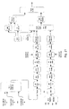
- Figure 24 shows a block diagram of a SMATV headend: Baseband packets of DVB-S2 services are used as input data.
- Mode adaptation is reused as much as possible from DVB-S2.
- the system works with Transport Stream Input or Generic Stream Input (DVB GSE protocol to adapt an IP stream into a generic stream).
- Both formats support single and multiple input stream modes, as shown in Figure 25 .
- This kind of mode adaptation allows stream specific (i.e. TS or GS) adjustment of the desired robustness level.
- SNR the higher the SNR, the higher the 'ModCod' mode is used (i.e. combination of modulation scheme and selected FEC mode).
- Figure 25 shows mode adaptation for DVB-C2, supporting single and multiple input streams (TS or GS).
- BCH encoding is performed according to DBV-S2. Use of 12-error correction BCH is proposed for all coderates in order to avoid a high error floor which is seen for the higher order modulations (1024QAM, 4096QAM) proposed for DVB-C2.
- LDPC encoding is performed according to DVB-S2.
- a bit interleaver shall be employed to optimize assignments between LDPC code bits and Gray mapped QAM symbol bits. As in DVB-T2 it shall consist of a block interleaver and a de-multiplexer.
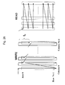
- the output of the LDPC encoder shall be parity interleaved first and then be stored into memory of Nc columns and Nr rows.
- the data are written column by column with column twisting offset tc and are read row by row.
- Figure 26 shows a Bit Interleaving scheme.
- the output N c -tuple ⁇ b 0,r , b 1,r , b 2,r , ..., b Nc-1,r ⁇ with respect to the r-th row is permuted into ⁇ y 0,r , y 1,r , y 2,r ..., y Nc-1,r ⁇ in de-multiplexer part, where each m bits belong to a 2 m -QAM symbol.
- a time interleaver is proposed for broadcast services.
- the interleaving length of the time interleaver is kept short in comparison to DVB-T2.
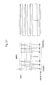
- Figure 27 shows the time interleaver operation.
- the time interleaver takes the output from the QAM encoder and writes the data into columns.
- the outputs are passed to the frequency interleaver by reading out the interleaver cells in rows.
- a typical interferer can be considered to be the 577 ⁇ s burst received from a GSM mobile phone. This duration corresponds to approximately one n4k symbol period. Depending on the severity of the erasure a 9/10 code rate or more robust code rate may be used for the LDPC encoder.
- Time interleaving shall be optional for interactive services (using adaptive OFDM):
- the frequency interleaver shall be used similar to DVB-T2. Since variable frequency slices are permitted for OFDM reception the interleaver size must be calculated dynamically by the transmitter as well as the receiver (i.e. the interleaver size varies depending on the number of subcarriers allocated).
- the purpose of the frequency interleaver, operating on the data cells of one OFDM symbol, is to map the data cells onto the N data available data carriers in each symbol.
- the frequency interleaver shall process the data cells of the OFDM symbol I of C2-frame m.
- a parameter M max is then defined according to Table 8.
- Table 8 Value of M max for the frequency interleaver FFT Size M max 4K 4 096
- the interleaved vector A m,l (a m,l,0 , a m,l,l ,a m,l2 ,...a m,l ,N data-1 ) is defined by:
- H ( q ) is a permutation function based on sequences R ' i defined by the following.
- a vector R i is derived from the vector R ' i by the bit permutations given in Table 9.
- Table 9 Bit permutations R ' i bit positions 10 9 8 7 6 5 4 3 2 1 0 R i bit positions ( H ) 7 10 5 8 1 2 4 9 0 3 6
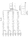
- FIG. 28 A schematic block diagram of the algorithm used to generate the permutation function is represented in Figure 28 : Frequency interleaver address generation scheme for the 4k mode.
- N data is signalled in L1 symbols.
- the modulation of the OFDM subcarriers shall be regular Quadrature Amplitude Modulation (QAM):
- QAM Quadrature Amplitude Modulation
- QAM constellations may be applicable for interactive services that can exploit the advantages of ACM (adaptive coding and modulation), i.e. transmitter and receiver exchange OFDM tonemaps that signal the chosen QAM constellation for each data slice. SNR-dependant adjustment of the chosen constellation and coding is possible.
- ACM adaptive coding and modulation
- the transmitted signal is organized in frames as described in section 3.5.
- Each frame has duration of T F , and consists of L F OFDM symbols.
- Each symbol is constituted by a set of K carriers transmitted with a duration T s . It is composed of two parts: a useful part with duration T u and a guard interval with duration ⁇ .
- the guard interval consists of a cyclic continuation of the useful part, T u , and is inserted before it.
- the symbols in an OFDM frame are numbered from 1 to L F . All symbols contain data and/or reference information.
- each symbol can in turn be considered to be divided into cells, each corresponding to the modulation carried on one carrier during one symbol.
- the OFDM symbols contain pilots that can be used for frame synchronization, frequency synchronization, time synchronization, channel estimation, and can also be used to track the phase noise.
- the carriers are indexed by k ⁇ [K min ; K max ] and determined by K min and K max .
- the spacing between adjacent carriers is 1/T U while the spacing between carriers K min and K max are determined by (K-1)/T U .
- the OFDM parameters are summarised in Table 10.
- the values for the various time-related parameters are given in multiples of the elementary period T and in microseconds.
- n 4k mode of operation is proposed as a good trade-off between symbol length, phase noise sensitivity as well as spectrum side lobe steepness. This is based on the DVB-H/T2 4k mode, within an 8 MHz channel.
- the system bandwidth can be extended to n multiples of 8 MHz.
- Table 10 illustrates the settings for several channel bandwidths where n varies from I to 4. Table 10: 4nk OFDM modulation for different channel bandwidths 8 MHz channel bandwidth 16 MHz channel bandwidth 24 MHz channel bandwidth 32 MHz channel bandwidth ...
- the proposed OFDM values are very similar to the main parameters of the DVB-H/T2 4k mode, including carrier spacing as well as the symbol duration.
- the framing structure is shown in Figure 29 , which is similar as to the above described Figure 16 .
- the super frame is divided into C2 frames which are further divided into OFDM symbols.
- a C2 frame always starts with one preamble symbol then two layer 1 signalling symbols and finally L F -3 data symbols.
- the duration of each symbol in the frame has the same period T s .
- the symbol period T s consists of the sum of guard interval duration T GI and the useful symbol duration T u .
- the overhead for signalling is therefore 3/323 (approx. 0.9%) for the preamble and L1 signalling symbols.
- Table 11 Frame periods of the 4nk system for different guard interval lengths Guard Interval Length Frame Period 1/64 147.0 msec 1/128 145.8 msec 1/256 145.3 msec
- L1 signalling data can be changed only at super frame boundaries.
- the super frame period can be set to its maximum value of (2 16 - 1)* T F , which is approximately 2 hours 37 minutes, as L1 signalling parameters are not envisaged to change frequently.
- the super frame length can be shortened as required.
- the super frame period is provided as an L signalling parameter.
- Zapping time without knowledge of the frequency data slice location is expected to require up to two complete C2 frame periods (288ms) depending on the relative timing of the start of the channel change to the start of a C2 frame.
- the scattered pilot density is derived from
- the repetition rate can be kept low.
- the scattered pilot pattern density is dependent on the guard interval size.
- pilot patterns are proposed Table 12: Scattered pilot patterns for the proposed C2 system OFDM mode Guard Interval Length Separation of pilot bearing carriers (x) Number of symbols forming one scattered pilot sequence (y) n 4k 1/64 4 12 n4k 1/128 4 24 n 4k 1/256 4 48
- Table 12 shows the shift in frequency of the pilot position after one symbol is four carriers.
- Figure 30 illustrates the pilot pattern (black dots) for a guard interval length of 1/64.
- the first as well as the last carrier of each OFDM symbol will always contain pilot carriers. According to the Nyquist criterion standalone frequency interpolation is possible for each OFDM symbol itself. However, improving the channel estimation quality by applying additional time interpolation is possible.
- a preamble defines the start of a new C2 frame.
- the preamble must allow the following functionalities:
- the preamble is divided into a training sequence phase and a L1 signalling phase.
- the training phase consists of 8 shortened training symbols; the overall length is one OFDM symbol (4096 samples).
- the succeeding two OFDM symbols contain the L1 signalling (including the related Guard Interval).
- Figure 31 illustrates the basic structure of one C2 frame (in the time domain) and Fig. 32 , which is similar to the above explained Figure 13 , shows the basic structure of one C2 frame in the frequency domain, and alignment of preamble and data part (32 MHz example).
- the proposed preamble provides all typical important functionalities independent from the tuning position.
- the ability to perform all preamble functionalities independent from the tuning position allows the usage of an arbitrary data slicing in the frequency domain.
- the width (bandwidth) of the data slices does not have to be aligned to any fixed segment size.
- the bandwidth of the preamble sequence is limited to the reception bandwidth of the segmented receiver (i.e. 8 MHz).
- the overall channel bandwidth of the transmission signal is equal to a multiple of this receiver bandwidth (i.e. tuner bandwidth).
- the density of the pilot carriers in the training symbols is adjusted to fulfil at least the Nyquist criterion.
- the following preamble is proposed:
- Each training sequence subblock is equal to the initial receiver bandwidth and contains a repetition of a basic pseudo noise sequence with optimized correlation properties, which allows several advantages:
- Figure 33 which is similar to the above explained Figure 6 , shows the proposed repetition of the basic pseudo noise sequence and a structure of the training symbol with repeated sequences for each receive segment.
- a repetition of 8 training sequences is proposed as a reasonable trade-off between correlation complexity and synchronization reliability.
- the pn-sequence has good overall autocorrelation (i.e. good correlation peak properties) as well as appropriate sliding correlation properties (i.e. delivering a correlation plateau, for example CAZAC sequences as used in WLAN preambles).
- synchronization reliability is increased further by inverting the last of the eight training sequences.
- the training sequence in its alignment to the 8 MHz raster does not allocate the complete bandwidth: Within each repetition, a number of carriers are omitted to meet spectrum characteristics and to allow for proper frequency offset compensation. For example, in order to allow a capture range of 250 kHz, the same bandwidth remains unused at both sides of the training sequence spectrum.
- L1 signalling provides information on all relevant physical layer specific parameters.
- L1 signalling follows the training sequence phase in each frame.
- the duration of the L1 signalling is two OFDM symbols.
- the bandwidth of the L1 signal is 4MHz, each two L1 blocks (also called signalling patterns) are aligned to the initial 8 MHz raster.
- the frequency behaviour of the L1 signalling has to reflect typical filter characteristics of a receiver as well as the overall spectrum mask:
- Figure 34 which is similar to Figure 15 explained above, illustrates the carrier allocation of the L1 symbols (signalling patterns).
- L1 signalling structure n of n4k 4 bits Current n of n4k 4 bits Guard Interval length 2 bits Superframe length 16 bits Frame number 16 bits Number of data slices 5 bits Loop over data slices ⁇ n - Segment number 4 bits Start carrier number 12 bits Data slice width (number of carriers) 12 bits Data slice QAM modulation 3 bits LDPC blocksize 1 bit LDPC coderate 3 bits Time interleaver enable 1 bit Number of notches 2 bits Loop over notches ⁇ Start carrier number 12 bit Notch width (number of carriers) 12 bit ⁇ End notch loop PSI/SI reprocessing 1 bit ⁇ End data slice loop Reserved 1 bit CRC_32 MIP 32 bits
- Table 13 indicates that up to 32 different frequency slices in one n4k channel are supported.
- the receiver tuner e.g. the receiving tuner of the receiving apparatus 63 shown in and explained in relation to Figure 18 , tunes to an arbitrary frequency band which is either aligned or not aligned to the 8 MHz raster in cable networks.
- the tuning window covers a complete preamble sequence and two complete L1 signalling blocks. Therefore the receiver is able to synchronize, to perform an initial channel estimation and to extract L1 signalling. From the L1 signalling, e.g.
- the receiver has knowledge of the location of the received and decoded signalling pattem(s) in relation to the present frame and can then tune to the frequency of the wanted data slice (the data slice is typically not aligned to the 8MHz raster) and is able to receive and decode all wanted data slices in all succeeding frames of this superframe in this tuning position.
- the preamble is designed in a way that allows all important frame related functionalities (i.e. receiver synchronization, channel estimation and L1 decoding) in any tuning position. Therefore the data slices, i.e. the data patterns as explained in relation to Figure 10 , need not follow any fixed segment allocation. An appropriate number of OFDM subcarriers can be allocated. The only condition regarding the width of one data slice is that it does not exceed the receiving bandwidth (i.e. 8 MHz minus 2* guard band (e.g. 7.6. MHz)). Each data slice has a constant number of data bits (i.e. data carriers) per frequency slice per super frame. This number of data bits per data slice may change from superframe to superframe.
- Figure 35 illustrates the building of the overall OFDM signal as the combination of several OFDM subblocks (data slices). Each signal encoding chain is mapped onto the matching number of subcarriers.
- Terrestrial services and the DVB cable system often share the same frequency range. Interferences between both services reduce the SNR of the affected service. Radiation from cable networks disturbs the operation of the terrestrial services. Similarly, the transmission quality of cable services suffers from the ingress of terrestrial services by causing additional noise on the cable medium.
- An example is shown in Figure 36 . Notching of OFDM carriers is used to protect the different communication systems from each other: The OFDM carriers allocated to the same frequency range(s) are omitted from the data communication.
- An example of the system described above on terrestrial side is flight security services and many more.
- Figure 36 is an example of notched C2 OFDM spectrum (red curve) and terrestrial services (e.g. flight security service, blue curve), sharing the same frequency range.
- terrestrial services e.g. flight security service, blue curve
- the notch width should be as narrow as possible, that is only those OFDM subcarriers that directly overlap with those terrestrial services should be omitted (c.f. Figure 36 ).
- the location of the notches is part of the L1 signalling:
- the first notched carrier and the notch width are part of the L1 signalling.
- the proposed C2 system shall be usable as downstream medium for interactive data services, as shown in Figure 37 . Similar to the existing DVB-C system the C2 system shall be able to integrate the DOCSIS downstream data traffic.
- the upstream channel is provided in a DOCSIS compliant way and is out of the scope of this document
- Figure 37 shows C2 as downstream channel for DOCSIS data.
- Examples of these kinds of interactive services are all DOCSIS based data communication, including all IP based services or Video on Demand (VoD).
- Figure 38 shows DOCSIS communication in the proposed C2 system.
- the proposed system is able to deploy the advantages of adaptive OFDM (ACM - adaptive coding and modulation):
- ACM - adaptive coding and modulation For interactive point to point communication services the modem and the transmitter can exchange their SNR conditions in their assigned frequency slice in order to optimize their data throughput.
- This technique provides a precise protection of the data slice as well as dynamic link adaptation to propagation conditions by targeting each individual terminal (C2 modem / receiver).
- FIG 38 an example cable network with the C2 headend and a number of connected C2 receivers / modems is depicted.
- the available SNR in each location changes.
- the C2 modem/receiver 1 is quite close to the headend and therefore any attenuation in the downlink spectrum is low.
- the modem will inform the headend about its good channel conditions, the headend selects an appropriate combination of modulation and coding with a very high throughput rate.
- the distance between the C2 headend and the C2 modem/receiver 2 is assumed to be very long, resulting in a higher attenuation in the receive spectrum.
- the available SNR range is therefore significantly lower, the C2 modem/receiver 2 informs the C2 headend to use a more robust combination of modulation and coding.
- the DVB-C2 transmit spectrum must fulfil an appropriate spectrum mask criteria. Since the proposed C2 system uses a n4k OFDM modulation with very high subcarrier QAM constellations, the sidelobe level at the channel border must be below the required SNR valued for the physical layer mode that demands the highest SNR value for QEF (quasi error free) reception in an AWGN environment.
- Figure 39 shows the relation and shows an OFDM spectrum overlapping between adjacent channels.
- Windowing and filtering are dual techniques to reduce out of band spectrum.
- the cut off behaviour of conventional filtering has a potential impact on the performance of high subcarrier modulation modes.
- windowing in the time domain causes no system degradation.
- the drawback of windowing is a partial overlap between consecutive symbols and the related degradation of the usable guard interval fraction.
- Figure 40 shows the basic principle of windowing.
- Figure 40 shows windowing of OFDM symbols in time domain.
- the overlap between consecutive OFDM symbols has the duration T TR .
- T TR the duration of the out of band spectrum is reduced.
- the OFDM specific overhead GI, pilots, guard bands, framing
- GI the OFDM specific overhead
- DVB-C 256 QAM requires 29.5 dB SNR for QEF operation.
- 1024-QAM with code rate 9/10 requires roughly the same signal to noise ratio.
Landscapes
- Engineering & Computer Science (AREA)
- Signal Processing (AREA)
- Computer Networks & Wireless Communication (AREA)
- Mobile Radio Communication Systems (AREA)
- Cable Transmission Systems, Equalization Of Radio And Reduction Of Echo (AREA)
- Time-Division Multiplex Systems (AREA)
- Two-Way Televisions, Distribution Of Moving Picture Or The Like (AREA)
- Circuits Of Receivers In General (AREA)
Priority Applications (1)
| Application Number | Priority Date | Filing Date | Title |
|---|---|---|---|
| EP12175157.2A EP2541828B1 (de) | 2008-06-04 | 2008-06-13 | Neue Rahmen- und Signalisierungsmusterstruktur für Mehrträgersysteme |
Applications Claiming Priority (3)
| Application Number | Priority Date | Filing Date | Title |
|---|---|---|---|
| EP08157549.0A EP2131519B1 (de) | 2008-06-04 | 2008-06-04 | Neuartige Rahmenstruktur für Mehrträgersysteme |
| EP12175157.2A EP2541828B1 (de) | 2008-06-04 | 2008-06-13 | Neue Rahmen- und Signalisierungsmusterstruktur für Mehrträgersysteme |
| EP08158291.8A EP2134044B1 (de) | 2008-06-04 | 2008-06-13 | Neue Rahmen- und Signalisierungsmusterstruktur für Mehrträgersysteme |
Related Parent Applications (2)
| Application Number | Title | Priority Date | Filing Date |
|---|---|---|---|
| EP08158291.8A Division EP2134044B1 (de) | 2008-06-04 | 2008-06-13 | Neue Rahmen- und Signalisierungsmusterstruktur für Mehrträgersysteme |
| EP08158291.8 Division | 2008-06-13 |
Publications (3)
| Publication Number | Publication Date |
|---|---|
| EP2541828A2 true EP2541828A2 (de) | 2013-01-02 |
| EP2541828A3 EP2541828A3 (de) | 2013-03-06 |
| EP2541828B1 EP2541828B1 (de) | 2014-07-23 |
Family
ID=40134086
Family Applications (6)
| Application Number | Title | Priority Date | Filing Date |
|---|---|---|---|
| EP08157549.0A Not-in-force EP2131519B1 (de) | 2008-06-04 | 2008-06-04 | Neuartige Rahmenstruktur für Mehrträgersysteme |
| EP12175157.2A Not-in-force EP2541828B1 (de) | 2008-06-04 | 2008-06-13 | Neue Rahmen- und Signalisierungsmusterstruktur für Mehrträgersysteme |
| EP08158291.8A Not-in-force EP2134044B1 (de) | 2008-06-04 | 2008-06-13 | Neue Rahmen- und Signalisierungsmusterstruktur für Mehrträgersysteme |
| EP12174965.9A Not-in-force EP2512059B1 (de) | 2008-06-04 | 2008-06-13 | Neue Rahmen- und Signalisierungsmusterstruktur für Mehrträgersysteme |
| EP08158271A Ceased EP2131520A1 (de) | 2008-06-04 | 2008-06-13 | Neue Rahmen- und Trainingsmusterstruktur für Mehrträgersysteme |
| EP12173455.2A Not-in-force EP2544421B1 (de) | 2008-06-04 | 2008-06-13 | Neue Rahmen- und Signalisierungsmusterstruktur für Mehrträgersysteme |
Family Applications Before (1)
| Application Number | Title | Priority Date | Filing Date |
|---|---|---|---|
| EP08157549.0A Not-in-force EP2131519B1 (de) | 2008-06-04 | 2008-06-04 | Neuartige Rahmenstruktur für Mehrträgersysteme |
Family Applications After (4)
| Application Number | Title | Priority Date | Filing Date |
|---|---|---|---|
| EP08158291.8A Not-in-force EP2134044B1 (de) | 2008-06-04 | 2008-06-13 | Neue Rahmen- und Signalisierungsmusterstruktur für Mehrträgersysteme |
| EP12174965.9A Not-in-force EP2512059B1 (de) | 2008-06-04 | 2008-06-13 | Neue Rahmen- und Signalisierungsmusterstruktur für Mehrträgersysteme |
| EP08158271A Ceased EP2131520A1 (de) | 2008-06-04 | 2008-06-13 | Neue Rahmen- und Trainingsmusterstruktur für Mehrträgersysteme |
| EP12173455.2A Not-in-force EP2544421B1 (de) | 2008-06-04 | 2008-06-13 | Neue Rahmen- und Signalisierungsmusterstruktur für Mehrträgersysteme |
Country Status (4)
| Country | Link |
|---|---|
| EP (6) | EP2131519B1 (de) |
| CN (4) | CN101599946B (de) |
| ES (2) | ES2432761T3 (de) |
| PL (2) | PL2131519T3 (de) |
Cited By (1)
| Publication number | Priority date | Publication date | Assignee | Title |
|---|---|---|---|---|
| CN110710176A (zh) * | 2017-06-09 | 2020-01-17 | 马维尔国际贸易有限公司 | 带有具有压缩ofdm符号的中间码的分组 |
Families Citing this family (12)
| Publication number | Priority date | Publication date | Assignee | Title |
|---|---|---|---|---|
| WO2011098427A2 (en) * | 2010-02-11 | 2011-08-18 | Sony Corporation | Mapping apparatus and method for transmission of data in a multi-carrier broadcast system |
| JP5696888B2 (ja) * | 2011-03-10 | 2015-04-08 | ソニー株式会社 | 受信装置、受信方法、およびプログラム |
| CN103281282B (zh) * | 2013-06-13 | 2016-04-06 | 湖南国科微电子股份有限公司 | 一种dvb-t2系统中频偏估计的方法 |
| WO2015046919A1 (en) | 2013-09-27 | 2015-04-02 | Lg Electronics Inc. | Apparatus for transmitting broadcast signals, apparatus for receiving broadcast signals, method for transmitting broadcast signals and method for receiving broadcast signals |
| CN112187399B (zh) * | 2014-08-25 | 2023-07-07 | 第一媒体有限责任公司 | 灵活的正交频分复用phy传输数据帧前导码的动态配置 |
| KR102391843B1 (ko) | 2015-03-09 | 2022-04-29 | 원 미디어, 엘엘씨 | 시스템 발견 및 시그널링 |
| CA3158869C (en) | 2015-03-13 | 2025-08-05 | Shanghai National Engineering Research Center Of Digital Television Co.,Ltd | Signalling coding and modulation method and demodulation and decoding method and device |
| CN106034007B (zh) * | 2015-03-13 | 2019-12-13 | 上海数字电视国家工程研究中心有限公司 | 信令编码调制方法和解调译码方法及装置 |
| CN106921469A (zh) * | 2015-03-20 | 2017-07-04 | 上海数字电视国家工程研究中心有限公司 | 信令编码调制方法和解调译码方法 |
| CN108024293B (zh) | 2016-11-04 | 2021-07-09 | 中兴通讯股份有限公司 | 一种传输带宽的配置方法及发射节点 |
| US10727994B2 (en) * | 2017-01-09 | 2020-07-28 | Qualcomm Incorporated | Using sequences of pilot repetitions for receiver adaptation |
| CN114096009B (zh) * | 2021-10-29 | 2024-11-01 | 中国电子科技集团公司第五十四研究所 | 一种灵活高效的多种类数据动态组帧方法 |
Family Cites Families (10)
| Publication number | Priority date | Publication date | Assignee | Title |
|---|---|---|---|---|
| KR100221336B1 (ko) * | 1996-12-28 | 1999-09-15 | 전주범 | 직교 주파수 분할 다중화 수신 시스템의 프레임 동기 장치 및 그 방법 |
| US5867478A (en) * | 1997-06-20 | 1999-02-02 | Motorola, Inc. | Synchronous coherent orthogonal frequency division multiplexing system, method, software and device |
| US7423968B2 (en) * | 2004-01-12 | 2008-09-09 | Intel Corporation | Systems and methods to convey additional signaling information in a wireless local area network |
| US20060088133A1 (en) | 2004-10-22 | 2006-04-27 | Industrial Technology Research Institute | Time-frequency correlation-based synchronization for coherent OFDM receiver |
| CN100566317C (zh) * | 2004-10-22 | 2009-12-02 | 财团法人工业技术研究院 | 基于频率相关性的相干正交频分复用接收器同步方法与装置 |
| EP1951635A1 (de) * | 2005-10-28 | 2008-08-06 | Excell Technologies, LLC | Gemischte zementzusammensetzung |
| US7760617B2 (en) | 2006-03-24 | 2010-07-20 | Lg Electronics Inc. | Method and structure of configuring preamble to support transmission of data symbol in a wireless communication system |
| CN101064577A (zh) * | 2006-04-29 | 2007-10-31 | 北京三星通信技术研究有限公司 | 下行控制信令的传输方法和设备 |
| JP4328812B2 (ja) * | 2006-10-23 | 2009-09-09 | Okiセミコンダクタ株式会社 | スキャッタードパイロット配置検出器 |
| US20080107011A1 (en) * | 2006-11-02 | 2008-05-08 | Mediatek Inc. | System, Apparatus, and Method for Processing a Received Orthogonal Frequency Division Multiplexing Signal |
-
2008
- 2008-06-04 PL PL08157549T patent/PL2131519T3/pl unknown
- 2008-06-04 EP EP08157549.0A patent/EP2131519B1/de not_active Not-in-force
- 2008-06-04 ES ES08157549T patent/ES2432761T3/es active Active
- 2008-06-13 EP EP12175157.2A patent/EP2541828B1/de not_active Not-in-force
- 2008-06-13 EP EP08158291.8A patent/EP2134044B1/de not_active Not-in-force
- 2008-06-13 PL PL08158291T patent/PL2134044T3/pl unknown
- 2008-06-13 EP EP12174965.9A patent/EP2512059B1/de not_active Not-in-force
- 2008-06-13 EP EP08158271A patent/EP2131520A1/de not_active Ceased
- 2008-06-13 ES ES08158291.8T patent/ES2438598T3/es active Active
- 2008-06-13 EP EP12173455.2A patent/EP2544421B1/de not_active Not-in-force
-
2009
- 2009-06-04 CN CN2009102031516A patent/CN101599946B/zh not_active Expired - Fee Related
- 2009-06-04 CN CN2009101415523A patent/CN101599944B/zh not_active Expired - Fee Related
- 2009-06-04 CN CN2009101415453A patent/CN101599943B/zh not_active Expired - Fee Related
- 2009-06-04 CN CN201210407228.3A patent/CN102957657B/zh not_active Expired - Fee Related
Non-Patent Citations (1)
| Title |
|---|
| None |
Cited By (2)
| Publication number | Priority date | Publication date | Assignee | Title |
|---|---|---|---|---|
| CN110710176A (zh) * | 2017-06-09 | 2020-01-17 | 马维尔国际贸易有限公司 | 带有具有压缩ofdm符号的中间码的分组 |
| CN110710176B (zh) * | 2017-06-09 | 2022-12-02 | 马维尔亚洲私人有限公司 | 带有具有压缩ofdm符号的中间码的分组 |
Also Published As
| Publication number | Publication date |
|---|---|
| EP2131520A1 (de) | 2009-12-09 |
| EP2131519A1 (de) | 2009-12-09 |
| PL2131519T3 (pl) | 2014-01-31 |
| CN101599943A (zh) | 2009-12-09 |
| CN101599944A (zh) | 2009-12-09 |
| EP2544421B1 (de) | 2018-02-28 |
| CN101599946A (zh) | 2009-12-09 |
| EP2544421A3 (de) | 2014-02-26 |
| PL2134044T3 (pl) | 2014-03-31 |
| CN102957657A (zh) | 2013-03-06 |
| EP2512059A3 (de) | 2014-02-26 |
| EP2131519B1 (de) | 2013-09-25 |
| EP2134044B1 (de) | 2013-11-06 |
| EP2541828A3 (de) | 2013-03-06 |
| EP2512059A2 (de) | 2012-10-17 |
| CN101599944B (zh) | 2012-12-12 |
| EP2134044A1 (de) | 2009-12-16 |
| CN101599943B (zh) | 2012-10-03 |
| EP2541828B1 (de) | 2014-07-23 |
| EP2512059B1 (de) | 2017-09-27 |
| CN102957657B (zh) | 2015-06-10 |
| ES2432761T3 (es) | 2013-12-05 |
| ES2438598T3 (es) | 2014-01-17 |
| EP2544421A2 (de) | 2013-01-09 |
| CN101599946B (zh) | 2013-01-09 |
Similar Documents
| Publication | Publication Date | Title |
|---|---|---|
| EP2131542B1 (de) | Neue Rahmen- und Signalisierungsmusterstruktur für Mehrträgersysteme | |
| EP2541828B1 (de) | Neue Rahmen- und Signalisierungsmusterstruktur für Mehrträgersysteme | |
| AU2010200287B2 (en) | New frame and data pattern structure for multi-carrier systems | |
| US8897390B2 (en) | Apparatus for transmitting and receiving a signal and method of transmitting and receiving a signal | |
| US9647730B2 (en) | Apparatus for transmitting and receiving a signal and method of transmitting and receiving a signal | |
| AU2009217407B2 (en) | New frame and data pattern structure for multi-carrier systems | |
| US8787497B2 (en) | Apparatus for transmitting and receiving a signal and method of transmitting and receiving a signal | |
| US20160227274A1 (en) | Broadcast receiving device and method for operating the same | |
| EP3242429A1 (de) | Rundfunksignalsendevorrichtung, rundfunksignalempfangsvorrichtung, rundfunksignalsendeverfahren und rundfunksignalempfangsverfahren | |
| EP3007437A1 (de) | Vorrichtung zum senden von rundfunksignalen, vorrichtung zum empfangen von rundfunksignalen, verfahren zum senden von rundfunksignalen und verfahren zum empfangen von rundfunksignalen | |
| EP2216928B1 (de) | Rahmen- und Datenmusterstruktur für Mehrträgersysteme | |
| EP2587709B1 (de) | Rahmen- und Datenmusterstruktur für Mehrträgersysteme | |
| JP6047215B2 (ja) | マルチキャリアシステムのための新たなフレーム及び信号パターン構造 |
Legal Events
| Date | Code | Title | Description |
|---|---|---|---|
| PUAI | Public reference made under article 153(3) epc to a published international application that has entered the european phase |
Free format text: ORIGINAL CODE: 0009012 |
|
| AC | Divisional application: reference to earlier application |
Ref document number: 2134044 Country of ref document: EP Kind code of ref document: P |
|
| AK | Designated contracting states |
Kind code of ref document: A2 Designated state(s): AT BE BG CH CY CZ DE DK EE ES FI FR GB GR HR HU IE IS IT LI LT LU LV MC MT NL NO PL PT RO SE SI SK TR |
|
| PUAL | Search report despatched |
Free format text: ORIGINAL CODE: 0009013 |
|
| AK | Designated contracting states |
Kind code of ref document: A3 Designated state(s): AT BE BG CH CY CZ DE DK EE ES FI FR GB GR HR HU IE IS IT LI LT LU LV MC MT NL NO PL PT RO SE SI SK TR |
|
| RIC1 | Information provided on ipc code assigned before grant |
Ipc: H04L 27/26 20060101ALI20130129BHEP Ipc: H04L 5/00 20060101AFI20130129BHEP |
|
| 17P | Request for examination filed |
Effective date: 20130615 |
|
| RBV | Designated contracting states (corrected) |
Designated state(s): AT BE BG CH CY CZ DE DK EE ES FI FR GB GR HR HU IE IS IT LI LT LU LV MC MT NL NO PL PT RO SE SI SK TR |
|
| GRAP | Despatch of communication of intention to grant a patent |
Free format text: ORIGINAL CODE: EPIDOSNIGR1 |
|
| INTG | Intention to grant announced |
Effective date: 20140214 |
|
| GRAS | Grant fee paid |
Free format text: ORIGINAL CODE: EPIDOSNIGR3 |
|
| GRAA | (expected) grant |
Free format text: ORIGINAL CODE: 0009210 |
|
| AC | Divisional application: reference to earlier application |
Ref document number: 2134044 Country of ref document: EP Kind code of ref document: P |
|
| AK | Designated contracting states |
Kind code of ref document: B1 Designated state(s): AT BE BG CH CY CZ DE DK EE ES FI FR GB GR HR HU IE IS IT LI LT LU LV MC MT NL NO PL PT RO SE SI SK TR |
|
| REG | Reference to a national code |
Ref country code: GB Ref legal event code: FG4D |
|
| REG | Reference to a national code |
Ref country code: CH Ref legal event code: EP |
|
| REG | Reference to a national code |
Ref country code: IE Ref legal event code: FG4D |
|
| REG | Reference to a national code |
Ref country code: AT Ref legal event code: REF Ref document number: 679378 Country of ref document: AT Kind code of ref document: T Effective date: 20140815 |
|
| REG | Reference to a national code |
Ref country code: DE Ref legal event code: R096 Ref document number: 602008033524 Country of ref document: DE Effective date: 20140911 |
|
| REG | Reference to a national code |
Ref country code: AT Ref legal event code: MK05 Ref document number: 679378 Country of ref document: AT Kind code of ref document: T Effective date: 20140723 |
|
| REG | Reference to a national code |
Ref country code: NL Ref legal event code: VDEP Effective date: 20140723 |
|
| REG | Reference to a national code |
Ref country code: LT Ref legal event code: MG4D |
|
| PG25 | Lapsed in a contracting state [announced via postgrant information from national office to epo] |
Ref country code: LT Free format text: LAPSE BECAUSE OF FAILURE TO SUBMIT A TRANSLATION OF THE DESCRIPTION OR TO PAY THE FEE WITHIN THE PRESCRIBED TIME-LIMIT Effective date: 20140723 Ref country code: PT Free format text: LAPSE BECAUSE OF FAILURE TO SUBMIT A TRANSLATION OF THE DESCRIPTION OR TO PAY THE FEE WITHIN THE PRESCRIBED TIME-LIMIT Effective date: 20141124 Ref country code: BG Free format text: LAPSE BECAUSE OF FAILURE TO SUBMIT A TRANSLATION OF THE DESCRIPTION OR TO PAY THE FEE WITHIN THE PRESCRIBED TIME-LIMIT Effective date: 20141023 Ref country code: ES Free format text: LAPSE BECAUSE OF FAILURE TO SUBMIT A TRANSLATION OF THE DESCRIPTION OR TO PAY THE FEE WITHIN THE PRESCRIBED TIME-LIMIT Effective date: 20140723 Ref country code: FI Free format text: LAPSE BECAUSE OF FAILURE TO SUBMIT A TRANSLATION OF THE DESCRIPTION OR TO PAY THE FEE WITHIN THE PRESCRIBED TIME-LIMIT Effective date: 20140723 Ref country code: NO Free format text: LAPSE BECAUSE OF FAILURE TO SUBMIT A TRANSLATION OF THE DESCRIPTION OR TO PAY THE FEE WITHIN THE PRESCRIBED TIME-LIMIT Effective date: 20141023 Ref country code: SE Free format text: LAPSE BECAUSE OF FAILURE TO SUBMIT A TRANSLATION OF THE DESCRIPTION OR TO PAY THE FEE WITHIN THE PRESCRIBED TIME-LIMIT Effective date: 20140723 Ref country code: GR Free format text: LAPSE BECAUSE OF FAILURE TO SUBMIT A TRANSLATION OF THE DESCRIPTION OR TO PAY THE FEE WITHIN THE PRESCRIBED TIME-LIMIT Effective date: 20141024 |
|
| PG25 | Lapsed in a contracting state [announced via postgrant information from national office to epo] |
Ref country code: HR Free format text: LAPSE BECAUSE OF FAILURE TO SUBMIT A TRANSLATION OF THE DESCRIPTION OR TO PAY THE FEE WITHIN THE PRESCRIBED TIME-LIMIT Effective date: 20140723 Ref country code: PL Free format text: LAPSE BECAUSE OF FAILURE TO SUBMIT A TRANSLATION OF THE DESCRIPTION OR TO PAY THE FEE WITHIN THE PRESCRIBED TIME-LIMIT Effective date: 20140723 Ref country code: NL Free format text: LAPSE BECAUSE OF FAILURE TO SUBMIT A TRANSLATION OF THE DESCRIPTION OR TO PAY THE FEE WITHIN THE PRESCRIBED TIME-LIMIT Effective date: 20140723 Ref country code: LV Free format text: LAPSE BECAUSE OF FAILURE TO SUBMIT A TRANSLATION OF THE DESCRIPTION OR TO PAY THE FEE WITHIN THE PRESCRIBED TIME-LIMIT Effective date: 20140723 Ref country code: AT Free format text: LAPSE BECAUSE OF FAILURE TO SUBMIT A TRANSLATION OF THE DESCRIPTION OR TO PAY THE FEE WITHIN THE PRESCRIBED TIME-LIMIT Effective date: 20140723 Ref country code: IS Free format text: LAPSE BECAUSE OF FAILURE TO SUBMIT A TRANSLATION OF THE DESCRIPTION OR TO PAY THE FEE WITHIN THE PRESCRIBED TIME-LIMIT Effective date: 20141123 Ref country code: CY Free format text: LAPSE BECAUSE OF FAILURE TO SUBMIT A TRANSLATION OF THE DESCRIPTION OR TO PAY THE FEE WITHIN THE PRESCRIBED TIME-LIMIT Effective date: 20140723 |
|
| REG | Reference to a national code |
Ref country code: DE Ref legal event code: R097 Ref document number: 602008033524 Country of ref document: DE |
|
| PG25 | Lapsed in a contracting state [announced via postgrant information from national office to epo] |
Ref country code: CZ Free format text: LAPSE BECAUSE OF FAILURE TO SUBMIT A TRANSLATION OF THE DESCRIPTION OR TO PAY THE FEE WITHIN THE PRESCRIBED TIME-LIMIT Effective date: 20140723 Ref country code: EE Free format text: LAPSE BECAUSE OF FAILURE TO SUBMIT A TRANSLATION OF THE DESCRIPTION OR TO PAY THE FEE WITHIN THE PRESCRIBED TIME-LIMIT Effective date: 20140723 Ref country code: SK Free format text: LAPSE BECAUSE OF FAILURE TO SUBMIT A TRANSLATION OF THE DESCRIPTION OR TO PAY THE FEE WITHIN THE PRESCRIBED TIME-LIMIT Effective date: 20140723 Ref country code: IT Free format text: LAPSE BECAUSE OF FAILURE TO SUBMIT A TRANSLATION OF THE DESCRIPTION OR TO PAY THE FEE WITHIN THE PRESCRIBED TIME-LIMIT Effective date: 20140723 Ref country code: RO Free format text: LAPSE BECAUSE OF FAILURE TO SUBMIT A TRANSLATION OF THE DESCRIPTION OR TO PAY THE FEE WITHIN THE PRESCRIBED TIME-LIMIT Effective date: 20140723 Ref country code: DK Free format text: LAPSE BECAUSE OF FAILURE TO SUBMIT A TRANSLATION OF THE DESCRIPTION OR TO PAY THE FEE WITHIN THE PRESCRIBED TIME-LIMIT Effective date: 20140723 |
|
| PLBE | No opposition filed within time limit |
Free format text: ORIGINAL CODE: 0009261 |
|
| STAA | Information on the status of an ep patent application or granted ep patent |
Free format text: STATUS: NO OPPOSITION FILED WITHIN TIME LIMIT |
|
| REG | Reference to a national code |
Ref country code: FR Ref legal event code: PLFP Year of fee payment: 8 |
|
| 26N | No opposition filed |
Effective date: 20150424 |
|
| PG25 | Lapsed in a contracting state [announced via postgrant information from national office to epo] |
Ref country code: SI Free format text: LAPSE BECAUSE OF FAILURE TO SUBMIT A TRANSLATION OF THE DESCRIPTION OR TO PAY THE FEE WITHIN THE PRESCRIBED TIME-LIMIT Effective date: 20140723 |
|
| PG25 | Lapsed in a contracting state [announced via postgrant information from national office to epo] |
Ref country code: MC Free format text: LAPSE BECAUSE OF FAILURE TO SUBMIT A TRANSLATION OF THE DESCRIPTION OR TO PAY THE FEE WITHIN THE PRESCRIBED TIME-LIMIT Effective date: 20140723 |
|
| REG | Reference to a national code |
Ref country code: CH Ref legal event code: PL |
|
| PG25 | Lapsed in a contracting state [announced via postgrant information from national office to epo] |
Ref country code: LU Free format text: LAPSE BECAUSE OF FAILURE TO SUBMIT A TRANSLATION OF THE DESCRIPTION OR TO PAY THE FEE WITHIN THE PRESCRIBED TIME-LIMIT Effective date: 20150613 |
|
| REG | Reference to a national code |
Ref country code: IE Ref legal event code: MM4A |
|
| REG | Reference to a national code |
Ref country code: DE Ref legal event code: R084 Ref document number: 602008033524 Country of ref document: DE |
|
| PG25 | Lapsed in a contracting state [announced via postgrant information from national office to epo] |
Ref country code: LI Free format text: LAPSE BECAUSE OF NON-PAYMENT OF DUE FEES Effective date: 20150630 Ref country code: CH Free format text: LAPSE BECAUSE OF NON-PAYMENT OF DUE FEES Effective date: 20150630 Ref country code: IE Free format text: LAPSE BECAUSE OF NON-PAYMENT OF DUE FEES Effective date: 20150613 |
|
| REG | Reference to a national code |
Ref country code: GB Ref legal event code: 746 Effective date: 20160412 |
|
| REG | Reference to a national code |
Ref country code: FR Ref legal event code: PLFP Year of fee payment: 9 |
|
| PG25 | Lapsed in a contracting state [announced via postgrant information from national office to epo] |
Ref country code: BE Free format text: LAPSE BECAUSE OF FAILURE TO SUBMIT A TRANSLATION OF THE DESCRIPTION OR TO PAY THE FEE WITHIN THE PRESCRIBED TIME-LIMIT Effective date: 20140723 |
|
| PG25 | Lapsed in a contracting state [announced via postgrant information from national office to epo] |
Ref country code: MT Free format text: LAPSE BECAUSE OF FAILURE TO SUBMIT A TRANSLATION OF THE DESCRIPTION OR TO PAY THE FEE WITHIN THE PRESCRIBED TIME-LIMIT Effective date: 20140723 |
|
| PG25 | Lapsed in a contracting state [announced via postgrant information from national office to epo] |
Ref country code: HU Free format text: LAPSE BECAUSE OF FAILURE TO SUBMIT A TRANSLATION OF THE DESCRIPTION OR TO PAY THE FEE WITHIN THE PRESCRIBED TIME-LIMIT; INVALID AB INITIO Effective date: 20080613 |
|
| REG | Reference to a national code |
Ref country code: FR Ref legal event code: PLFP Year of fee payment: 10 |
|
| PG25 | Lapsed in a contracting state [announced via postgrant information from national office to epo] |
Ref country code: TR Free format text: LAPSE BECAUSE OF FAILURE TO SUBMIT A TRANSLATION OF THE DESCRIPTION OR TO PAY THE FEE WITHIN THE PRESCRIBED TIME-LIMIT Effective date: 20140723 |
|
| REG | Reference to a national code |
Ref country code: FR Ref legal event code: PLFP Year of fee payment: 11 |
|
| PGFP | Annual fee paid to national office [announced via postgrant information from national office to epo] |
Ref country code: DE Payment date: 20180625 Year of fee payment: 11 |
|
| PGFP | Annual fee paid to national office [announced via postgrant information from national office to epo] |
Ref country code: FR Payment date: 20180620 Year of fee payment: 11 |
|
| PGFP | Annual fee paid to national office [announced via postgrant information from national office to epo] |
Ref country code: GB Payment date: 20180620 Year of fee payment: 11 |
|
| REG | Reference to a national code |
Ref country code: DE Ref legal event code: R119 Ref document number: 602008033524 Country of ref document: DE |
|
| GBPC | Gb: european patent ceased through non-payment of renewal fee |
Effective date: 20190613 |
|
| PG25 | Lapsed in a contracting state [announced via postgrant information from national office to epo] |
Ref country code: DE Free format text: LAPSE BECAUSE OF NON-PAYMENT OF DUE FEES Effective date: 20200101 Ref country code: GB Free format text: LAPSE BECAUSE OF NON-PAYMENT OF DUE FEES Effective date: 20190613 |
|
| PG25 | Lapsed in a contracting state [announced via postgrant information from national office to epo] |
Ref country code: FR Free format text: LAPSE BECAUSE OF NON-PAYMENT OF DUE FEES Effective date: 20190630 |