EP2542289B1 - Patientenschnittstelle mit nockenradeinstellungsmechanismus - Google Patents
Patientenschnittstelle mit nockenradeinstellungsmechanismus Download PDFInfo
- Publication number
- EP2542289B1 EP2542289B1 EP11710565.0A EP11710565A EP2542289B1 EP 2542289 B1 EP2542289 B1 EP 2542289B1 EP 11710565 A EP11710565 A EP 11710565A EP 2542289 B1 EP2542289 B1 EP 2542289B1
- Authority
- EP
- European Patent Office
- Prior art keywords
- cam wheel
- pivot arm
- patient
- interface device
- support structure
- Prior art date
- Legal status (The legal status is an assumption and is not a legal conclusion. Google has not performed a legal analysis and makes no representation as to the accuracy of the status listed.)
- Not-in-force
Links
- 230000007246 mechanism Effects 0.000 title description 10
- 230000008878 coupling Effects 0.000 claims description 37
- 238000010168 coupling process Methods 0.000 claims description 37
- 238000005859 coupling reaction Methods 0.000 claims description 37
- 210000001061 forehead Anatomy 0.000 claims description 18
- 210000003128 head Anatomy 0.000 claims description 11
- 230000007423 decrease Effects 0.000 claims description 3
- 230000029058 respiratory gaseous exchange Effects 0.000 description 6
- 238000007789 sealing Methods 0.000 description 3
- 238000004891 communication Methods 0.000 description 2
- 239000012530 fluid Substances 0.000 description 2
- 238000000034 method Methods 0.000 description 2
- 208000001797 obstructive sleep apnea Diseases 0.000 description 2
- 238000009423 ventilation Methods 0.000 description 2
- 206010007559 Cardiac failure congestive Diseases 0.000 description 1
- 206010019280 Heart failures Diseases 0.000 description 1
- 230000008901 benefit Effects 0.000 description 1
- 230000008859 change Effects 0.000 description 1
- 208000037265 diseases, disorders, signs and symptoms Diseases 0.000 description 1
- 208000035475 disorder Diseases 0.000 description 1
- 210000003238 esophagus Anatomy 0.000 description 1
- 230000006872 improvement Effects 0.000 description 1
- 238000004519 manufacturing process Methods 0.000 description 1
- 230000004048 modification Effects 0.000 description 1
- 238000012986 modification Methods 0.000 description 1
- 230000000241 respiratory effect Effects 0.000 description 1
- 201000002859 sleep apnea Diseases 0.000 description 1
- 238000002560 therapeutic procedure Methods 0.000 description 1
- 238000004448 titration Methods 0.000 description 1
Images



Classifications
-
- A—HUMAN NECESSITIES
- A61—MEDICAL OR VETERINARY SCIENCE; HYGIENE
- A61M—DEVICES FOR INTRODUCING MEDIA INTO, OR ONTO, THE BODY; DEVICES FOR TRANSDUCING BODY MEDIA OR FOR TAKING MEDIA FROM THE BODY; DEVICES FOR PRODUCING OR ENDING SLEEP OR STUPOR
- A61M16/00—Devices for influencing the respiratory system of patients by gas treatment, e.g. ventilators; Tracheal tubes
- A61M16/08—Bellows; Connecting tubes ; Water traps; Patient circuits
- A61M16/0816—Joints or connectors
-
- A—HUMAN NECESSITIES
- A61—MEDICAL OR VETERINARY SCIENCE; HYGIENE
- A61M—DEVICES FOR INTRODUCING MEDIA INTO, OR ONTO, THE BODY; DEVICES FOR TRANSDUCING BODY MEDIA OR FOR TAKING MEDIA FROM THE BODY; DEVICES FOR PRODUCING OR ENDING SLEEP OR STUPOR
- A61M16/00—Devices for influencing the respiratory system of patients by gas treatment, e.g. ventilators; Tracheal tubes
- A61M16/06—Respiratory or anaesthetic masks
-
- A—HUMAN NECESSITIES
- A61—MEDICAL OR VETERINARY SCIENCE; HYGIENE
- A61M—DEVICES FOR INTRODUCING MEDIA INTO, OR ONTO, THE BODY; DEVICES FOR TRANSDUCING BODY MEDIA OR FOR TAKING MEDIA FROM THE BODY; DEVICES FOR PRODUCING OR ENDING SLEEP OR STUPOR
- A61M16/00—Devices for influencing the respiratory system of patients by gas treatment, e.g. ventilators; Tracheal tubes
- A61M16/06—Respiratory or anaesthetic masks
- A61M16/0605—Means for improving the adaptation of the mask to the patient
-
- A—HUMAN NECESSITIES
- A61—MEDICAL OR VETERINARY SCIENCE; HYGIENE
- A61M—DEVICES FOR INTRODUCING MEDIA INTO, OR ONTO, THE BODY; DEVICES FOR TRANSDUCING BODY MEDIA OR FOR TAKING MEDIA FROM THE BODY; DEVICES FOR PRODUCING OR ENDING SLEEP OR STUPOR
- A61M16/00—Devices for influencing the respiratory system of patients by gas treatment, e.g. ventilators; Tracheal tubes
- A61M16/06—Respiratory or anaesthetic masks
- A61M16/0605—Means for improving the adaptation of the mask to the patient
- A61M16/0611—Means for improving the adaptation of the mask to the patient with a gusset portion
-
- A—HUMAN NECESSITIES
- A61—MEDICAL OR VETERINARY SCIENCE; HYGIENE
- A61M—DEVICES FOR INTRODUCING MEDIA INTO, OR ONTO, THE BODY; DEVICES FOR TRANSDUCING BODY MEDIA OR FOR TAKING MEDIA FROM THE BODY; DEVICES FOR PRODUCING OR ENDING SLEEP OR STUPOR
- A61M16/00—Devices for influencing the respiratory system of patients by gas treatment, e.g. ventilators; Tracheal tubes
- A61M16/06—Respiratory or anaesthetic masks
- A61M16/0605—Means for improving the adaptation of the mask to the patient
- A61M16/0633—Means for improving the adaptation of the mask to the patient with forehead support
- A61M16/0638—Means for improving the adaptation of the mask to the patient with forehead support in the form of a pivot
-
- A—HUMAN NECESSITIES
- A61—MEDICAL OR VETERINARY SCIENCE; HYGIENE
- A61M—DEVICES FOR INTRODUCING MEDIA INTO, OR ONTO, THE BODY; DEVICES FOR TRANSDUCING BODY MEDIA OR FOR TAKING MEDIA FROM THE BODY; DEVICES FOR PRODUCING OR ENDING SLEEP OR STUPOR
- A61M16/00—Devices for influencing the respiratory system of patients by gas treatment, e.g. ventilators; Tracheal tubes
- A61M16/06—Respiratory or anaesthetic masks
- A61M16/0605—Means for improving the adaptation of the mask to the patient
- A61M16/0633—Means for improving the adaptation of the mask to the patient with forehead support
- A61M16/0644—Means for improving the adaptation of the mask to the patient with forehead support having the means for adjusting its position
- A61M16/065—Means for improving the adaptation of the mask to the patient with forehead support having the means for adjusting its position in the form of a pivot
-
- A—HUMAN NECESSITIES
- A61—MEDICAL OR VETERINARY SCIENCE; HYGIENE
- A61M—DEVICES FOR INTRODUCING MEDIA INTO, OR ONTO, THE BODY; DEVICES FOR TRANSDUCING BODY MEDIA OR FOR TAKING MEDIA FROM THE BODY; DEVICES FOR PRODUCING OR ENDING SLEEP OR STUPOR
- A61M16/00—Devices for influencing the respiratory system of patients by gas treatment, e.g. ventilators; Tracheal tubes
- A61M16/06—Respiratory or anaesthetic masks
- A61M16/0683—Holding devices therefor
-
- A—HUMAN NECESSITIES
- A61—MEDICAL OR VETERINARY SCIENCE; HYGIENE
- A61M—DEVICES FOR INTRODUCING MEDIA INTO, OR ONTO, THE BODY; DEVICES FOR TRANSDUCING BODY MEDIA OR FOR TAKING MEDIA FROM THE BODY; DEVICES FOR PRODUCING OR ENDING SLEEP OR STUPOR
- A61M16/00—Devices for influencing the respiratory system of patients by gas treatment, e.g. ventilators; Tracheal tubes
- A61M16/06—Respiratory or anaesthetic masks
- A61M16/0605—Means for improving the adaptation of the mask to the patient
- A61M16/0633—Means for improving the adaptation of the mask to the patient with forehead support
- A61M16/0644—Means for improving the adaptation of the mask to the patient with forehead support having the means for adjusting its position
Definitions
- the present invention relates to patient interface devices for transporting a gas to and/or from an airway of a user, and, in particular, to a patient interface device including a cam wheel adjustment mechanism for dynamically adjusting a component of the patient interface device, such as a mask, cushion, or forehead support.
- Non-invasive ventilation and pressure support therapies involve the placement of a patient interface device including a mask component on the face of a patient.
- the mask component may be, without limitation, a nasal mask that covers the patient's nose, a nasal cushion having nasal prongs that are received within the patient's nares, a nasal/oral mask that covers the nose and mouth, or a full face mask that covers the patient's face.
- the patient interface device interfaces the ventilator or pressure support device with the airway of the patient, so that a flow of breathing gas can be delivered from the pressure/flow generating device to the airway of the patient. It is known to maintain such devices on the face of a wearer by a headgear having one or more straps adapted to fit over/around the patient's head.
- Exemplary patient interfaces of this kind are known from: WO 2007/084905 A2 , US 2006/213521 A1 , WO 2005/018523 A2 , WO 2006/074517 A1 , WO 2007/021777 A2 , US 2007/062537 A1 , US 2006/118117 A1 and WO 03/035156 A2 .
- a patient interface device which comprises a support structure; a pivot arm pivotably coupled to the support structure and structured to pivot about an axis; a patient coupling member coupled to the pivot arm; and a cam wheel rotateably coupled to the support structure and engaging the pivot arm, wherein a rotation of the cam wheel relative to the support structure and the pivot arm causes the pivot arm to pivot about the axis, thereby moving the patient coupling member relative to the support structure along a path of movement.
- the cam wheel comprises a cylindrically shaped member having a central bore and left and right outside walls, wherein both the left outside wall and the right outside wall vary in height from a maximum at a top middle portion of the cam wheel to a minimum at a bottom middle portion of the cam wheel, and wherein the pivot arm continuously engages the cam wheel at two locations on the cam wheel as the cam wheel is rotated relative to the pivot arm.
- a patient interface device which comprises a support structure; a pivot arm pivotably coupled to the support structure and structured to pivot about an axis; a patient coupling member coupled to the support structure, a forehead support coupled to the pivot arm, and a cam wheel rotateably coupled to the support structure and engaging the pivot arm, wherein a rotation of the cam wheel relative to the support structure and the pivot arm causes the pivot arm to pivot about the axis, thereby moving the forehead support relative to the patient coupling member along a path of movement.
- the cam wheel comprises a cylindrically shaped member having a central bore and left and right outside walls, wherein both the left outside wall and the right outside wall vary in height from a maximum at a top middle portion of the cam wheel to a minimum at a bottom middle portion of the cam wheel, and wherein the pivot arm continuously engages the cam wheel at two locations on the cam wheel as the cam wheel is rotated relative to the pivot arm.
- the word "unitary” means a component is created as a single piece or unit. That is, a component that includes pieces that are created separately and then coupled together as a unit is not a “unitary” component or body.
- the statement that two or more parts or components "engage” one another shall mean that the parts exert a force against one another either directly or through one or more intermediate parts or components.
- the term “number” shall mean one or an integer greater than one (i.e., a plurality).
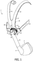
- FIG. 1 is an isometric view and FIG. 2 is an exploded view of a patient interface device 2 according to one exemplary embodiment of the present invention.
- Patient interface device 2 includes a patient coupling member 4, which in the illustrated embodiment is a nasal mask.
- a patient coupling member 4 is coupled to elbow conduit 6, which, in turn, is coupled to pivot arm conduit 8.
- Pivot arm conduit 8 is structured to be coupled to a delivery conduit (not shown) which is in fluid communication with a pressure generating device (also not shown) that is structured to generate a flow of breathing gas which is delivered to the patient through patient coupling member 4.
- the pressure generating device may include, without limitation, a ventilator, constant pressure support device (such as a continuous positive airway pressure device, or CPAP device), a variable pressure support device (e.g., BIPAP®, Bi-Flex®, or C-FlexTM devices manufactured and distributed by Philips Respironics of Murrysville, Pennsylvania), or an auto-titration pressure support device.
- a ventilator such as a continuous positive airway pressure device, or CPAP device
- a variable pressure support device e.g., BIPAP®, Bi-Flex®, or C-FlexTM devices manufactured and distributed by Philips Respironics of Murrysville, Pennsylvania
- an auto-titration pressure support device e.g., the delivery conduit that is coupled to pivot arm conduit 8 is adapted to extend over the patient's head when a headgear assembly 10 of patient interface device 2, described below, is worn on the head of the patient.
- patient interface device 2 includes a headgear assembly 10 adapted to fit over/around the patient's head to hold patient coupling member 4 in place on the face of the patient.
- Headgear assembly 10 includes a rigid support structure 12 adapted to fit over the forehead, top and rear portions of the patient's head.
- Support structure 12 includes a base portion 14 having arms 16, 18 extending therefrom.
- base portion 14 has an extension member 20 extending from a first side thereof and an extension member 24 extending from a second side thereof.
- Each extension member 20, 24 includes a respective loop 22, 26, which is structured to receive a respective headgear strap 28, 30 of headgear assembly 10 for securing headgear assembly 10 and thus patient interface device 2 to the head of the patient.
- Base portion 14 of support structure 12 further includes a post portion 32 extending from a front face thereof.
- Post portion 32 includes a post arm 34 having aperture 38 formed therein, and a post arm 36 having an aperture 40 formed therein.
- Patent interface device 2 also includes a cam wheel 42 that is described in greater detail below in connection with FIGS. 3A-3E , which are top plan, bottom plan, right side elevational, top side elevational, and isomeric views, respectively, of the cam wheel.
- Cam wheel 42 includes central bore 44.
- pivot arm conduit 8 when patient interface device 2 is assembled, cam wheel 42 is placed over post portion 32 in a manner in which post arms 34, 36 of post portion 32 are received through central bore 44 of cam wheel 42. Cam wheel 42 is free to rotate about post portion 32.
- the top end 46 of pivot arm conduit 8 includes posts 48, 50 on opposite sides thereof. As seen in FIG. 1 , when patient interface device 2 is assembled, each post 48, 50 of pivot arm conduit 8 is rotateably received and held within a respective aperture 38, 40 of base portion 14. Pivot arm conduit 8, when so mounted to base portion 32, secure and holds cam wheel 42 in place between pivot arm conduit 8 and base portion 14. In addition, as seen in FIG. 1 , pivot arm conduit 8 will always contact cam wheel 42 in two places as cam wheel 42 is rotated about post portion 32.
- cam wheel 42 is a cylindrically shaped member having left and right outside walls 52, 54 that vary in height from a maximum at top middle portion 56 of cam wheel 42 to a minimum at bottom middle portion 58 of cam wheel 42. More particularly, in the illustrated embodiment, the height of each of left outside wall 52 and right outside wall 54 tapers and decreases linearly from top middle portion 56 to bottom middle portion 58. Left and right outside walls 52, 54 are provided with ridges 66 to facilitate gripping and turning of cam wheel 42 as described elsewhere herein. While an generally linear change in height for the wall of the cam wheel is shown, it is to be understood that the present invention contemplates that the wall of the cam wheel can have other shapes or changes in height.
- pivot arm conduit 8 will always contact cam wheel 42 in two places as cam wheel 42 is rotated about post portion 32.
- patient coupling member 4 will engage the patient's face.
- the varying height of the walls of cam wheel 42 as defined by left and right outside walls 52, 54 and the two points of contact between cam wheel 42 and pivot arm conduit 8 described above will cause pivot arm conduit 8 to pivot about the axis through pivot arm conduit 8 that is defined by posts 48, 50.
- Such pivoting causes bottom end 68 of pivot arm conduit 8, and thus patient coupling member 4 attached thereto, to move inwardly and outwardly along a defined path of movement in a corresponding fashion.
- cam wheel 42 results in movement of patient coupling member 4 relative to support structure 12.
- support structure 12 is fixed on the user's head.
- Pivot arm conduit 8, post portion 32, and cam wheel 42 thus provides an easy to use, reduced complexity adjustment mechanism for patient interface device 2. Because cam wheel 42 is able to be turned both clockwise and counter clockwise, the position of patient coupling member 4 can be readily and easily adjusted both inwardly and outwardly relative to the patient's airway when the patient interface device is worn by the user. Furthermore, as the outer diameter of cam wheel 42 is made larger, it becomes easier to use by people with less strength and/or dexterity in their hands, such as the elderly.
- FIG. 4 is an isometric view of a patient interface device 70 according to an alternative exemplary embodiment of the present invention.
- Patient interface device 70 includes patient coupling member 72 that, like in the previous embodiment, is also a patient sealing element that seals an airway of the user.
- the patient sealing element is a nasal mask that includes a cushion that contacts the face of the user.
- any type of patient coupling member such as a nasal/oral mask, nasal cannula or a full face mask, which facilitates the delivery of a flow of breathing gas to the airway of a patient, may be used as patient coupling member 72 while remaining within the scope of the present invention.
- Patient coupling member 72 (i.e., the cushion) is fluidly coupled to a rigid support structure 74 which in turn is coupled to elbow conduit 76.
- Elbow conduit 76 is structured to be coupled to a delivery conduit (not shown) which is in fluid communication with a pressure generating device (also not shown) that is structured to generate a flow of breathing gas which is delivered to the patient through patient coupling member 72.
- Support structure 74 includes a base portion 78 having a post portion 80 extending therefrom.
- post portion 80 has a pair of posts 82 extending from opposites side thereof.
- Support structure 74 further includes a pair of extension members 84 extending from opposites side thereof, wherein each extension member 84 includes a loop 86 which is structured to receive a respective lower headgear strap of a headgear assembly (not shown) for securing patient interface device 70 to the head of the patient.
- Patient interface device 70 further includes a forehead support 88 that includes forehead cushion 90 that is coupled to support frame 92.
- Forehead support 88 is structured to provide additional support for patient interface device 70 by engaging the forehead of the patient.
- Support frame 92 includes loops 94 provided at opposite ends thereof. Each loop 94 is structured to receive a respective upper headgear strap of a headgear assembly (not shown) for securing patient interface device 70 to the head of the patient.
- Support frame 92 is pivotably coupled to upper end 96 of a support arm 98.
- the forehead support can have any configuration.
- the length of support arm 98 can be made adjustable.
- the forehead cushion can include one or more cushions having any suitable configuration.
- headgear attaching elements in addition to or other than loops 94 can be provided on the forehead support.
- a lower end 100 of support arm 98 includes a loop portion 102 that is structured to receive therethrough post portion 80 of support structure 74, as shown in FIG. 4 .
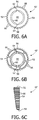
- cam wheel 42' according to an alternative embodiment shown in FIGS. 6A-6E , is inserted over post portion 80 such that post portion 80 is received through central bore 44 of cam wheel 42'.
- Cam wheel 42' is similar to cam wheel 42, and like parts are labeled with like reference numerals.
- interior wall 60 of cam wheel 42' includes notches 62, 64 for providing clearance for post 82 as cam wheel 42' is slid over post portion 80.
- cam wheel 42 then rests against base portion 78, and cam wheel is permitted to rotate about post portion 80.
- post portion 80 is received through loop portion 102, each post 82 is received and held within a respective aperture 104 provided on opposite sides of loop portion 102 such that loop portion 102 and support arm 98 are able to pivot about the axis defined by posts 82.
- cam wheel is held in place between lower end 100 of support arm 98 and base portion 78 as a result of the engagement between loop portion 102 and post portion 80.
- lower end 100 of support arm 98 will always contact cam wheel 42' in two places as cam wheel 42' is rotated about post portion 80.
- patient coupling member 72 will engage the patient's face and forehead support 88 will engage the patient's forehead.
- the varying height of the walls of cam wheel 42' as defined by left and right outside walls 52, 54 and the two points of contact between cam wheel 42 and lower end 100 of support arm 98 described above will support arm 98 to pivot about the axis through that is defined by posts 82.
- support arm 98 serves as a pivot arm that is pivotaly coupled to support structure 74.
- cam wheel 42' results in movement of forehead support 88 relative to patient coupling member.
- support structure 12 is fixed on the user's head.
- FIG. 5 is an isometric view of a patient interface device 106 according to an alternative exemplary embodiment of the present invention.
- Patient interface device is similar to patient interface device 70, and like components are labeled with like reference numerals.
- Patient interface device 106 includes patient coupling member 108, which is a nasal/oral mask that covers the nose and mouth, and alternative rigid support structure 110 to which patient coupling member 108 is fluidly coupled.
- rotating the cam wheel causes the patient coupling member to move or pivot in a direction that causes the cushion to move in a longitudinal direction, i.e., to move generally in-line with a center-line of the user. This allows the user, for example, to adjust the pressure applied by cushion at the bridge of the nose.
- the present invention also contemplate moving the patient coupling member in other directions, such as laterally, using the cam wheel or using multiple cam wheels.
- other adjustment mechanisms can be provided with the patient interface device.
Landscapes
- Health & Medical Sciences (AREA)
- Life Sciences & Earth Sciences (AREA)
- General Health & Medical Sciences (AREA)
- Engineering & Computer Science (AREA)
- Anesthesiology (AREA)
- Biomedical Technology (AREA)
- Heart & Thoracic Surgery (AREA)
- Pulmonology (AREA)
- Hematology (AREA)
- Animal Behavior & Ethology (AREA)
- Emergency Medicine (AREA)
- Public Health (AREA)
- Veterinary Medicine (AREA)
- Accommodation For Nursing Or Treatment Tables (AREA)
- Orthopedics, Nursing, And Contraception (AREA)
- Rehabilitation Tools (AREA)
- Respiratory Apparatuses And Protective Means (AREA)
Claims (12)
- Patientenschnittstellenvorrichtung (2), die Folgendes umfasst:eine Halterungsstruktur (12);einen Schwenkarm (8), der schwenkbar mit der Halterungsstruktur (12) gekoppelt ist und konstruiert ist, um um eine Achse zu schwenken;ein Patientenkopplungselement (4), das mit dem Schwenkarm (8) gekoppelt ist; undein Nockenrad (42), das drehbar mit der Halterungsstruktur (12) gekoppelt ist und in den Schwenkarm (8) eingreift, wobei eine Drehung des Nockenrads (42) relativ zu der Halterungsstruktur (12) und dem Schwenkarm (8) den Schwenkarm (8) veranlasst, um die Achse zu schwenken, wodurch das Patientenkopplungselement (4) relativ zu der Halterungsstruktur (12) auf einem Bewegungspfad bewegt wird, wobei das Nockenrad (42) ein zylindrisch geformtes Element mit einer zentralen Bohrung (44) und linken und rechten Außenwänden (52, 54) umfasst, wobei sowohl die linke Außenwand (52) als auch die rechte Außenwand (54) in der Höhe von einem Maximum am oberen Mittelabschnitt (56) des Nockenrads (42) zu einem Minimum am unteren Mittelabschnitt (58) des Nockenrads (42) variieren, und wobei der Schwenkarm (8) kontinuierlich in das Nockenrad (42) an zwei Stellen am Nockenrad (42) eingreift, wenn das Nockenrad (42) relativ zu dem Schwenkarm (8) gedreht wird.
- Patientenschnittstellenvorrichtung nach Anspruch 1, wobei das Patientenkopplungselement (4) eine Maske ist und der Schwenkarm (8) eine Leitung ist, die fluidmäßig mit der Maske gekoppelt ist.
- Patientenschnittstellenvorrichtung nach Anspruch 2, wobei die Halterungsstruktur (12) Teil eines Kopfgeschirrs (10) der Patientenschnittstellenvorrichtung (2) ist.
- Patientenschnittstellenvorrichtung nach Anspruch 3, wobei die Halterungsstruktur (12) konstruiert ist, um über die Stirn, den oberen und den hinteren Teil des Kopfs eines Patienten zu passen, wenn die Patientenschnittstellenvorrichtung (2) von dem Patienten getragen wird.
- Patientenschnittstellenvorrichtung nach Anspruch 1, wobei die Halterungsstruktur (12) einen Pfostenteil (32) umfasst, wobei der Schwenkarm (8) schwenkbar mit dem Pfostenteil (32) gekoppelt ist, und wobei das Nockenrad (42) zwischen einem Basisteil (14) der Halterungsstruktur (12) und dem Schwenkarm (8) positioniert ist.
- Patientenschnittstellenvorrichtung nach Anspruch 5, wobei der Pfostenteil (32) einen ersten Pfostenarm (34) mit einer ersten Apertur (38) und einen zweiten Pfostenarm (36) mit einer zweiten Apertur (40) umfasst, wobei ein erstes Ende (46) des Schwenkarms (8) einen ersten Pfosten (48) und einen zweiten Pfosten (50) umfasst, wobei der erste Pfosten (48) drehbar in der ersten Apertur (38) aufgenommen ist und der zweite Pfosten (50) drehbar in der zweiten Apertur (40) aufgenommen ist, und wobei das Patientenkopplungselement (4) mit einem zweiten Ende (68) des Schwenkarms (8) gegenüber dem ersten Ende (46) gekoppelt ist.
- Patientenschnittstellenvorrichtung nach Anspruch 1, wobei sich die Höhe von sowohl der linken Außenwand (52) als auch der rechten Außenwand (54) verjüngt und linear von dem oberen Mittelabschnitt (56) zum unteren Mittelabschnitt (58) abnimmt.
- Patientenschnittstellenvorrichtung (70, 106), die Folgendes umfasst:eine Halterungsstruktur (74, 110);einen Schwenkarm (98), der schwenkbar mit der Halterungsstruktur (74, 110) gekoppelt ist und konstruiert ist, um um eine Achse zu schwenken;ein Patientenkopplungselement (72, 108), das mit der Halterungsstruktur (74, 110) gekoppelt ist;eine Stirnhalterung (88), die mit dem Schwenkarm (98) gekoppelt ist; undein Nockenrad (42'), das drehbar mit der Halterungsstruktur (74, 110) gekoppelt ist und in den Schwenkarm (98) eingreift, wobei eine Drehung des Nockenrads (42') relativ zu der Halterungsstruktur (74, 110) und dem Schwenkarm (98) den Schwenkarm (98) veranlasst, um die Achse zu schwenken, wodurch die Stirnhalterung (88) relativ zu dem Patientenhalterungselement (72, 108) auf einem Bewegungspfad bewegt wird, wobei das Nockenrad (42') ein zylindrisch geformtes Element mit einer zentralen Bohrung (44) und linken und rechten Außenwänden (52, 54) umfasst, wobei sowohl die linke Außenwand (52) als auch die rechte Außenwand (54) in der Höhe von einem Maximum am oberen Mittelabschnitt (56) des Nockenrads (42') zu einem Minimum am unteren Mittelabschnitt (58) des Nockenrads (42') variieren, und wobei der Schwenkarm (98) kontinuierlich in das Nockenrad (42') an zwei Stellen am Nockenrad (42') eingreift, wenn das Nockenrad (42') relativ zu dem Schwenkarm (98) gedreht wird.
- Patientenschnittstellenvorrichtung nach Anspruch 8, wobei das Patientenkopplungselement (72, 108) eine Maske ist.
- Patientenschnittstellenvorrichtung nach Anspruch 8, wobei die Halterungsstruktur (74, 110) einen Pfostenteil (80) umfasst, wobei der Schwenkarm (98) schwenkbar mit dem Pfostenteil (80) gekoppelt ist, und wobei das Nockenrad (42') zwischen einem Basisteil (78) der Halterungsstruktur (74, 110) und dem Schwenkarm (98) positioniert ist.
- Patientenschnittstellenvorrichtung nach Anspruch 10, wobei ein erstes Ende des Pfostenteils (80) hiervon ausgehend einen ersten Pfosten (82) und einen zweiten Pfosten (82) umfasst, wobei ein erstes Ende (100) des Schwenkarms (98) einen Schlaufenteil (102) mit darin angebracht einer ersten Apertur (104) und einer zweiten Apertur (104) umfasst, wobei der Pfostenteil (32) durch den Schlaufenteil (102) aufgenommen wird, wobei der erste Pfosten (82) drehbar in der ersten Apertur (104) aufgenommen ist und der zweiten Pfosten (82) drehbar in der zweiten Apertur (104) aufgenommen ist, und wobei das Patientenkopplungselement (72, 108) mit einem zweiten Ende (96) des Schwenkarms (98) gegenüber dem ersten Ende (100) gekoppelt ist.
- Patientenschnittstellenvorrichtung nach Anspruch 8, wobei sich die Höhe von sowohl der linken Außenwand (52) als auch der rechten Außenwand (54) verjüngt und linear von dem oberen Mittelabschnitt (56) zum unteren Mittelabschnitt (58) abnimmt.
Applications Claiming Priority (2)
| Application Number | Priority Date | Filing Date | Title |
|---|---|---|---|
| US30991410P | 2010-03-03 | 2010-03-03 | |
| PCT/IB2011/050608 WO2011107899A1 (en) | 2010-03-03 | 2011-02-14 | Patient interface device having cam wheel adjustment mechanism |
Publications (2)
| Publication Number | Publication Date |
|---|---|
| EP2542289A1 EP2542289A1 (de) | 2013-01-09 |
| EP2542289B1 true EP2542289B1 (de) | 2016-04-20 |
Family
ID=44170580
Family Applications (1)
| Application Number | Title | Priority Date | Filing Date |
|---|---|---|---|
| EP11710565.0A Not-in-force EP2542289B1 (de) | 2010-03-03 | 2011-02-14 | Patientenschnittstelle mit nockenradeinstellungsmechanismus |
Country Status (7)
| Country | Link |
|---|---|
| US (3) | US8746249B2 (de) |
| EP (1) | EP2542289B1 (de) |
| JP (1) | JP5965847B2 (de) |
| CN (1) | CN102781505B (de) |
| AU (1) | AU2011222667B2 (de) |
| BR (1) | BR112012021782A2 (de) |
| WO (1) | WO2011107899A1 (de) |
Families Citing this family (29)
| Publication number | Priority date | Publication date | Assignee | Title |
|---|---|---|---|---|
| US9155855B2 (en) | 2002-12-06 | 2015-10-13 | Fisher & Paykel Healthcare Limited | Mouthpiece |
| NZ578010A (en) * | 2006-06-16 | 2011-05-27 | Resmed Ltd | Forehead support for facial masks extendable and contratable with the use of an adjustment knob |
| CN103533982A (zh) * | 2011-05-13 | 2014-01-22 | 皇家飞利浦有限公司 | 具有竖直轮驱动机构的可调节前额支撑件的患者界面装置 |
| WO2013098694A1 (en) * | 2011-12-27 | 2013-07-04 | Koninklijke Philips Electronics N.V. | Patient interface arrangement with adjustable forehead support |
| CN104363947B (zh) * | 2012-06-20 | 2016-08-17 | 皇家飞利浦有限公司 | 具有铰接的前额垫附接件的患者界面系统 |
| US9011610B2 (en) | 2012-06-22 | 2015-04-21 | Ecolab Usa Inc. | Solid fast draining/drying rinse aid for high total dissolved solid water conditions |
| WO2014045245A1 (en) * | 2012-09-21 | 2014-03-27 | Koninklijke Philips N.V. | Respiratory mask having a magnetically supported cushion |
| EP2950864B1 (de) * | 2013-02-04 | 2023-12-06 | ResMed Pty Ltd | Atemgerät |
| US10987477B2 (en) | 2013-02-04 | 2021-04-27 | ResMed Pty Ltd | Respiratory apparatus |
| US10413692B2 (en) | 2013-02-04 | 2019-09-17 | ResMed Pty Ltd | Cushion assembly |
| US10456540B2 (en) * | 2013-03-15 | 2019-10-29 | ResMed Pty Ltd | Patient interface systems for ensuring effective seal |
| SG10201607352RA (en) * | 2013-04-11 | 2016-10-28 | Fisher & Paykel Healthcare Ltd | Flexible mask coupling |
| US9186045B2 (en) | 2013-11-22 | 2015-11-17 | Christopher Murphy | Medical scope attachment device and system |
| US10232137B2 (en) | 2014-05-22 | 2019-03-19 | Resmed Limited | Patient interface |
| US20180071476A1 (en) * | 2014-11-19 | 2018-03-15 | Koninklijke Philips N.V. | Frame/headgear adjustment assembly |
| USD827126S1 (en) * | 2015-09-09 | 2018-08-28 | Neores Ab | Mask for respiratory therapies |
| CN105413037B (zh) * | 2015-12-31 | 2018-10-12 | 北京怡和嘉业医疗科技股份有限公司 | 呼吸面罩 |
| WO2017114454A1 (zh) * | 2015-12-31 | 2017-07-06 | 北京怡和嘉业医疗科技股份有限公司 | 呼吸面罩 |
| CN105413036B (zh) * | 2015-12-31 | 2018-03-09 | 北京怡和嘉业医疗科技股份有限公司 | 呼吸面罩 |
| CN106072910B (zh) * | 2016-06-17 | 2018-02-02 | 冯晶晶 | 卡头式医用口罩的制造方法 |
| RU2661272C2 (ru) * | 2016-09-09 | 2018-07-13 | Трейнингмаск Л.Л.К. | Устройство для дыхания с сопротивлением |
| EP3522967B1 (de) * | 2016-10-04 | 2020-11-11 | Koninklijke Philips N.V. | Magnetischer quetschschutz für eine leitung |
| US11980718B2 (en) * | 2017-06-19 | 2024-05-14 | Loewenstein Medical Technology S.A. | Breathing mask with breathing gas opening in the mask body |
| CN109125874B (zh) * | 2017-06-19 | 2023-09-15 | 律维施泰因医学技术股份有限公司 | 在面罩本体中具有呼吸气体开口的呼吸面罩 |
| EP3773846B1 (de) | 2018-03-29 | 2023-11-29 | ResMed Pty Ltd | Leitung mit magnetischem verbinder |
| WO2019211150A1 (en) * | 2018-05-02 | 2019-11-07 | Koninklijke Philips N.V. | Intraluminal medical imaging interface devices and systems |
| US10322312B1 (en) | 2018-06-01 | 2019-06-18 | TrainingMask L.L.C. | Resistance and filtration breathing device |
| IT202000024334A1 (it) * | 2020-10-15 | 2022-04-15 | Silvio Marino | Dispositivo di protezione delle vie respiratorie |
| TWI827453B (zh) * | 2023-01-18 | 2023-12-21 | 新廣業股份有限公司 | 防脫的組合式呼吸面罩 |
Citations (1)
| Publication number | Priority date | Publication date | Assignee | Title |
|---|---|---|---|---|
| US20060118117A1 (en) * | 2002-11-06 | 2006-06-08 | Michael Berthon-Jones | Mask and components thereof |
Family Cites Families (14)
| Publication number | Priority date | Publication date | Assignee | Title |
|---|---|---|---|---|
| US4498471A (en) | 1982-09-28 | 1985-02-12 | U.S.D. Corp. | First and second stage regulator system for breathing gas |
| WO2003035156A2 (de) | 2001-10-22 | 2003-05-01 | Map Medizin-Technologie Gmbh | Atemmaskenanordnung sowie applikationsvorrichtung und stirnauflageeinrichtung hiervon |
| US7357136B2 (en) * | 2003-08-18 | 2008-04-15 | Ric Investments, Llc | Patient interface assembly and system using same |
| DE202006021250U1 (de) * | 2005-01-12 | 2014-02-11 | Resmed Limited | Stirnstützen für Gesichtsmasken |
| US7546837B2 (en) * | 2005-03-16 | 2009-06-16 | Ric Investments, Llc | Interface with rolling diaphragm |
| US7665465B2 (en) * | 2005-03-25 | 2010-02-23 | Ric Investments, Llc | Headgear assembly for a respiratory support system |
| US8245711B2 (en) * | 2005-08-15 | 2012-08-21 | Ric Investments, Llc | Patient interface with adjustable cushion |
| US20070062537A1 (en) | 2005-09-14 | 2007-03-22 | Paul Chiesa | Forehead support for a respiratory mask |
| WO2007048174A1 (en) | 2005-10-25 | 2007-05-03 | Resmed Ltd | Interchangeable mask assembly |
| US7931026B2 (en) | 2006-01-20 | 2011-04-26 | Ric Investments, Llc | Adjustable conduit coupling assembly |
| US8028698B2 (en) | 2006-09-18 | 2011-10-04 | Invacare Corporation | Breathing mask |
| CN101455871B (zh) | 2007-07-30 | 2016-01-27 | 瑞思迈有限公司 | 患者接口 |
| EP2022528B1 (de) | 2007-07-30 | 2016-03-09 | Resmed Limited | Patientenschnittstelle |
| EP3698837A1 (de) * | 2009-06-24 | 2020-08-26 | ResMed Pty Ltd | Einstellbares maskensystem und zugehörige verfahren |
-
2011
- 2011-02-14 EP EP11710565.0A patent/EP2542289B1/de not_active Not-in-force
- 2011-02-14 JP JP2012555518A patent/JP5965847B2/ja not_active Expired - Fee Related
- 2011-02-14 CN CN201180012009.9A patent/CN102781505B/zh active Active
- 2011-02-14 BR BR112012021782A patent/BR112012021782A2/pt not_active Application Discontinuation
- 2011-02-14 AU AU2011222667A patent/AU2011222667B2/en not_active Ceased
- 2011-02-14 US US13/320,796 patent/US8746249B2/en active Active
- 2011-02-14 WO PCT/IB2011/050608 patent/WO2011107899A1/en not_active Ceased
-
2014
- 2014-05-20 US US14/282,555 patent/US9821133B2/en active Active
-
2017
- 2017-10-25 US US15/793,176 patent/US10549061B2/en active Active
Patent Citations (1)
| Publication number | Priority date | Publication date | Assignee | Title |
|---|---|---|---|---|
| US20060118117A1 (en) * | 2002-11-06 | 2006-06-08 | Michael Berthon-Jones | Mask and components thereof |
Also Published As
| Publication number | Publication date |
|---|---|
| US20180043127A1 (en) | 2018-02-15 |
| WO2011107899A1 (en) | 2011-09-09 |
| BR112012021782A2 (pt) | 2016-05-17 |
| CN102781505B (zh) | 2015-08-12 |
| AU2011222667B2 (en) | 2014-07-24 |
| JP2013521041A (ja) | 2013-06-10 |
| US8746249B2 (en) | 2014-06-10 |
| CN102781505A (zh) | 2012-11-14 |
| US10549061B2 (en) | 2020-02-04 |
| US9821133B2 (en) | 2017-11-21 |
| AU2011222667A1 (en) | 2012-11-01 |
| EP2542289A1 (de) | 2013-01-09 |
| US20140251337A1 (en) | 2014-09-11 |
| JP5965847B2 (ja) | 2016-08-10 |
| US20120090617A1 (en) | 2012-04-19 |
Similar Documents
| Publication | Publication Date | Title |
|---|---|---|
| AU2011222667B2 (en) | Patient interface device having cam wheel adjustment mechanism | |
| US11511065B2 (en) | Patient interface device with auto-adjusting cushion | |
| US9901696B2 (en) | Patient interface device with tilt angle adjusting mechanism | |
| AU2010342299B2 (en) | Replaceable nasal pillow | |
| US9433741B2 (en) | Custom adjustable patient interface device | |
| US20140366885A1 (en) | Patient interface device with automatically tilting cushion | |
| EP2994183A1 (de) | Stabilisierte maske | |
| US9446214B2 (en) | Patient interface device including a moveable wedge forehead adjustment assembly | |
| WO2011048519A1 (en) | Patient interface device with adjustable cheek support | |
| EP3220991A1 (de) | Rahmen-/kopfbedeckungsjustiereinrichtung | |
| US20150151064A1 (en) | Patient interface system with articulating forehead pad attachment | |
| US9821132B2 (en) | Patient interface device including an adjustable forehead support having a vertical wheel drive mechanism |
Legal Events
| Date | Code | Title | Description |
|---|---|---|---|
| PUAI | Public reference made under article 153(3) epc to a published international application that has entered the european phase |
Free format text: ORIGINAL CODE: 0009012 |
|
| 17P | Request for examination filed |
Effective date: 20121004 |
|
| AK | Designated contracting states |
Kind code of ref document: A1 Designated state(s): AL AT BE BG CH CY CZ DE DK EE ES FI FR GB GR HR HU IE IS IT LI LT LU LV MC MK MT NL NO PL PT RO RS SE SI SK SM TR |
|
| DAX | Request for extension of the european patent (deleted) | ||
| RAP1 | Party data changed (applicant data changed or rights of an application transferred) |
Owner name: KONINKLIJKE PHILIPS N.V. |
|
| 17Q | First examination report despatched |
Effective date: 20150723 |
|
| GRAP | Despatch of communication of intention to grant a patent |
Free format text: ORIGINAL CODE: EPIDOSNIGR1 |
|
| RIC1 | Information provided on ipc code assigned before grant |
Ipc: A61M 16/08 20060101ALI20150902BHEP Ipc: A61M 16/06 20060101AFI20150902BHEP |
|
| INTG | Intention to grant announced |
Effective date: 20150921 |
|
| GRAS | Grant fee paid |
Free format text: ORIGINAL CODE: EPIDOSNIGR3 |
|
| GRAA | (expected) grant |
Free format text: ORIGINAL CODE: 0009210 |
|
| AK | Designated contracting states |
Kind code of ref document: B1 Designated state(s): AL AT BE BG CH CY CZ DE DK EE ES FI FR GB GR HR HU IE IS IT LI LT LU LV MC MK MT NL NO PL PT RO RS SE SI SK SM TR |
|
| REG | Reference to a national code |
Ref country code: GB Ref legal event code: FG4D |
|
| REG | Reference to a national code |
Ref country code: CH Ref legal event code: EP |
|
| REG | Reference to a national code |
Ref country code: AT Ref legal event code: REF Ref document number: 791720 Country of ref document: AT Kind code of ref document: T Effective date: 20160515 |
|
| REG | Reference to a national code |
Ref country code: IE Ref legal event code: FG4D |
|
| REG | Reference to a national code |
Ref country code: DE Ref legal event code: R096 Ref document number: 602011025564 Country of ref document: DE |
|
| REG | Reference to a national code |
Ref country code: LT Ref legal event code: MG4D |
|
| REG | Reference to a national code |
Ref country code: AT Ref legal event code: MK05 Ref document number: 791720 Country of ref document: AT Kind code of ref document: T Effective date: 20160420 |
|
| REG | Reference to a national code |
Ref country code: NL Ref legal event code: MP Effective date: 20160420 |
|
| PG25 | Lapsed in a contracting state [announced via postgrant information from national office to epo] |
Ref country code: NL Free format text: LAPSE BECAUSE OF FAILURE TO SUBMIT A TRANSLATION OF THE DESCRIPTION OR TO PAY THE FEE WITHIN THE PRESCRIBED TIME-LIMIT Effective date: 20160420 Ref country code: LT Free format text: LAPSE BECAUSE OF FAILURE TO SUBMIT A TRANSLATION OF THE DESCRIPTION OR TO PAY THE FEE WITHIN THE PRESCRIBED TIME-LIMIT Effective date: 20160420 Ref country code: FI Free format text: LAPSE BECAUSE OF FAILURE TO SUBMIT A TRANSLATION OF THE DESCRIPTION OR TO PAY THE FEE WITHIN THE PRESCRIBED TIME-LIMIT Effective date: 20160420 Ref country code: NO Free format text: LAPSE BECAUSE OF FAILURE TO SUBMIT A TRANSLATION OF THE DESCRIPTION OR TO PAY THE FEE WITHIN THE PRESCRIBED TIME-LIMIT Effective date: 20160720 Ref country code: PL Free format text: LAPSE BECAUSE OF FAILURE TO SUBMIT A TRANSLATION OF THE DESCRIPTION OR TO PAY THE FEE WITHIN THE PRESCRIBED TIME-LIMIT Effective date: 20160420 |
|
| PG25 | Lapsed in a contracting state [announced via postgrant information from national office to epo] |
Ref country code: GR Free format text: LAPSE BECAUSE OF FAILURE TO SUBMIT A TRANSLATION OF THE DESCRIPTION OR TO PAY THE FEE WITHIN THE PRESCRIBED TIME-LIMIT Effective date: 20160721 Ref country code: RS Free format text: LAPSE BECAUSE OF FAILURE TO SUBMIT A TRANSLATION OF THE DESCRIPTION OR TO PAY THE FEE WITHIN THE PRESCRIBED TIME-LIMIT Effective date: 20160420 Ref country code: LV Free format text: LAPSE BECAUSE OF FAILURE TO SUBMIT A TRANSLATION OF THE DESCRIPTION OR TO PAY THE FEE WITHIN THE PRESCRIBED TIME-LIMIT Effective date: 20160420 Ref country code: SE Free format text: LAPSE BECAUSE OF FAILURE TO SUBMIT A TRANSLATION OF THE DESCRIPTION OR TO PAY THE FEE WITHIN THE PRESCRIBED TIME-LIMIT Effective date: 20160420 Ref country code: HR Free format text: LAPSE BECAUSE OF FAILURE TO SUBMIT A TRANSLATION OF THE DESCRIPTION OR TO PAY THE FEE WITHIN THE PRESCRIBED TIME-LIMIT Effective date: 20160420 Ref country code: ES Free format text: LAPSE BECAUSE OF FAILURE TO SUBMIT A TRANSLATION OF THE DESCRIPTION OR TO PAY THE FEE WITHIN THE PRESCRIBED TIME-LIMIT Effective date: 20160420 Ref country code: AT Free format text: LAPSE BECAUSE OF FAILURE TO SUBMIT A TRANSLATION OF THE DESCRIPTION OR TO PAY THE FEE WITHIN THE PRESCRIBED TIME-LIMIT Effective date: 20160420 Ref country code: PT Free format text: LAPSE BECAUSE OF FAILURE TO SUBMIT A TRANSLATION OF THE DESCRIPTION OR TO PAY THE FEE WITHIN THE PRESCRIBED TIME-LIMIT Effective date: 20160822 |
|
| PG25 | Lapsed in a contracting state [announced via postgrant information from national office to epo] |
Ref country code: BE Free format text: LAPSE BECAUSE OF FAILURE TO SUBMIT A TRANSLATION OF THE DESCRIPTION OR TO PAY THE FEE WITHIN THE PRESCRIBED TIME-LIMIT Effective date: 20160420 Ref country code: IT Free format text: LAPSE BECAUSE OF FAILURE TO SUBMIT A TRANSLATION OF THE DESCRIPTION OR TO PAY THE FEE WITHIN THE PRESCRIBED TIME-LIMIT Effective date: 20160420 |
|
| REG | Reference to a national code |
Ref country code: DE Ref legal event code: R097 Ref document number: 602011025564 Country of ref document: DE |
|
| PG25 | Lapsed in a contracting state [announced via postgrant information from national office to epo] |
Ref country code: CZ Free format text: LAPSE BECAUSE OF FAILURE TO SUBMIT A TRANSLATION OF THE DESCRIPTION OR TO PAY THE FEE WITHIN THE PRESCRIBED TIME-LIMIT Effective date: 20160420 Ref country code: DK Free format text: LAPSE BECAUSE OF FAILURE TO SUBMIT A TRANSLATION OF THE DESCRIPTION OR TO PAY THE FEE WITHIN THE PRESCRIBED TIME-LIMIT Effective date: 20160420 Ref country code: RO Free format text: LAPSE BECAUSE OF FAILURE TO SUBMIT A TRANSLATION OF THE DESCRIPTION OR TO PAY THE FEE WITHIN THE PRESCRIBED TIME-LIMIT Effective date: 20160420 Ref country code: SK Free format text: LAPSE BECAUSE OF FAILURE TO SUBMIT A TRANSLATION OF THE DESCRIPTION OR TO PAY THE FEE WITHIN THE PRESCRIBED TIME-LIMIT Effective date: 20160420 Ref country code: EE Free format text: LAPSE BECAUSE OF FAILURE TO SUBMIT A TRANSLATION OF THE DESCRIPTION OR TO PAY THE FEE WITHIN THE PRESCRIBED TIME-LIMIT Effective date: 20160420 |
|
| PLBE | No opposition filed within time limit |
Free format text: ORIGINAL CODE: 0009261 |
|
| REG | Reference to a national code |
Ref country code: FR Ref legal event code: PLFP Year of fee payment: 7 |
|
| STAA | Information on the status of an ep patent application or granted ep patent |
Free format text: STATUS: NO OPPOSITION FILED WITHIN TIME LIMIT |
|
| PG25 | Lapsed in a contracting state [announced via postgrant information from national office to epo] |
Ref country code: SM Free format text: LAPSE BECAUSE OF FAILURE TO SUBMIT A TRANSLATION OF THE DESCRIPTION OR TO PAY THE FEE WITHIN THE PRESCRIBED TIME-LIMIT Effective date: 20160420 |
|
| 26N | No opposition filed |
Effective date: 20170123 |
|
| PG25 | Lapsed in a contracting state [announced via postgrant information from national office to epo] |
Ref country code: SI Free format text: LAPSE BECAUSE OF FAILURE TO SUBMIT A TRANSLATION OF THE DESCRIPTION OR TO PAY THE FEE WITHIN THE PRESCRIBED TIME-LIMIT Effective date: 20160420 |
|
| PG25 | Lapsed in a contracting state [announced via postgrant information from national office to epo] |
Ref country code: MC Free format text: LAPSE BECAUSE OF FAILURE TO SUBMIT A TRANSLATION OF THE DESCRIPTION OR TO PAY THE FEE WITHIN THE PRESCRIBED TIME-LIMIT Effective date: 20160420 |
|
| REG | Reference to a national code |
Ref country code: CH Ref legal event code: PL |
|
| GBPC | Gb: european patent ceased through non-payment of renewal fee |
Effective date: 20170214 |
|
| PG25 | Lapsed in a contracting state [announced via postgrant information from national office to epo] |
Ref country code: CH Free format text: LAPSE BECAUSE OF NON-PAYMENT OF DUE FEES Effective date: 20170228 Ref country code: LI Free format text: LAPSE BECAUSE OF NON-PAYMENT OF DUE FEES Effective date: 20170228 |
|
| REG | Reference to a national code |
Ref country code: IE Ref legal event code: MM4A |
|
| PG25 | Lapsed in a contracting state [announced via postgrant information from national office to epo] |
Ref country code: LU Free format text: LAPSE BECAUSE OF NON-PAYMENT OF DUE FEES Effective date: 20170214 |
|
| REG | Reference to a national code |
Ref country code: FR Ref legal event code: PLFP Year of fee payment: 8 |
|
| PG25 | Lapsed in a contracting state [announced via postgrant information from national office to epo] |
Ref country code: IE Free format text: LAPSE BECAUSE OF NON-PAYMENT OF DUE FEES Effective date: 20170214 Ref country code: GB Free format text: LAPSE BECAUSE OF NON-PAYMENT OF DUE FEES Effective date: 20170214 |
|
| PG25 | Lapsed in a contracting state [announced via postgrant information from national office to epo] |
Ref country code: MT Free format text: LAPSE BECAUSE OF NON-PAYMENT OF DUE FEES Effective date: 20170214 |
|
| PG25 | Lapsed in a contracting state [announced via postgrant information from national office to epo] |
Ref country code: AL Free format text: LAPSE BECAUSE OF FAILURE TO SUBMIT A TRANSLATION OF THE DESCRIPTION OR TO PAY THE FEE WITHIN THE PRESCRIBED TIME-LIMIT Effective date: 20160420 |
|
| PG25 | Lapsed in a contracting state [announced via postgrant information from national office to epo] |
Ref country code: HU Free format text: LAPSE BECAUSE OF FAILURE TO SUBMIT A TRANSLATION OF THE DESCRIPTION OR TO PAY THE FEE WITHIN THE PRESCRIBED TIME-LIMIT; INVALID AB INITIO Effective date: 20110214 |
|
| PG25 | Lapsed in a contracting state [announced via postgrant information from national office to epo] |
Ref country code: BG Free format text: LAPSE BECAUSE OF FAILURE TO SUBMIT A TRANSLATION OF THE DESCRIPTION OR TO PAY THE FEE WITHIN THE PRESCRIBED TIME-LIMIT Effective date: 20160420 |
|
| PG25 | Lapsed in a contracting state [announced via postgrant information from national office to epo] |
Ref country code: CY Free format text: LAPSE BECAUSE OF NON-PAYMENT OF DUE FEES Effective date: 20160420 |
|
| PG25 | Lapsed in a contracting state [announced via postgrant information from national office to epo] |
Ref country code: MK Free format text: LAPSE BECAUSE OF FAILURE TO SUBMIT A TRANSLATION OF THE DESCRIPTION OR TO PAY THE FEE WITHIN THE PRESCRIBED TIME-LIMIT Effective date: 20160420 |
|
| PG25 | Lapsed in a contracting state [announced via postgrant information from national office to epo] |
Ref country code: TR Free format text: LAPSE BECAUSE OF FAILURE TO SUBMIT A TRANSLATION OF THE DESCRIPTION OR TO PAY THE FEE WITHIN THE PRESCRIBED TIME-LIMIT Effective date: 20160420 |
|
| PG25 | Lapsed in a contracting state [announced via postgrant information from national office to epo] |
Ref country code: IS Free format text: LAPSE BECAUSE OF FAILURE TO SUBMIT A TRANSLATION OF THE DESCRIPTION OR TO PAY THE FEE WITHIN THE PRESCRIBED TIME-LIMIT Effective date: 20160820 |
|
| PGFP | Annual fee paid to national office [announced via postgrant information from national office to epo] |
Ref country code: FR Payment date: 20230223 Year of fee payment: 13 |
|
| PGFP | Annual fee paid to national office [announced via postgrant information from national office to epo] |
Ref country code: DE Payment date: 20220628 Year of fee payment: 13 |
|
| REG | Reference to a national code |
Ref country code: DE Ref legal event code: R119 Ref document number: 602011025564 Country of ref document: DE |
|
| PG25 | Lapsed in a contracting state [announced via postgrant information from national office to epo] |
Ref country code: DE Free format text: LAPSE BECAUSE OF NON-PAYMENT OF DUE FEES Effective date: 20240903 |
|
| PG25 | Lapsed in a contracting state [announced via postgrant information from national office to epo] |
Ref country code: FR Free format text: LAPSE BECAUSE OF NON-PAYMENT OF DUE FEES Effective date: 20240229 |
|
| PG25 | Lapsed in a contracting state [announced via postgrant information from national office to epo] |
Ref country code: FR Free format text: LAPSE BECAUSE OF NON-PAYMENT OF DUE FEES Effective date: 20240229 Ref country code: DE Free format text: LAPSE BECAUSE OF NON-PAYMENT OF DUE FEES Effective date: 20240903 |