EP2542435B1 - Antriebsstrang mit einem automatisierten gruppengetriebe - Google Patents
Antriebsstrang mit einem automatisierten gruppengetriebe Download PDFInfo
- Publication number
- EP2542435B1 EP2542435B1 EP11718080.2A EP11718080A EP2542435B1 EP 2542435 B1 EP2542435 B1 EP 2542435B1 EP 11718080 A EP11718080 A EP 11718080A EP 2542435 B1 EP2542435 B1 EP 2542435B1
- Authority
- EP
- European Patent Office
- Prior art keywords
- drive
- group
- electric machine
- transmission
- drive train
- Prior art date
- Legal status (The legal status is an assumption and is not a legal conclusion. Google has not performed a legal analysis and makes no representation as to the accuracy of the status listed.)
- Active
Links
Images



Classifications
-
- B—PERFORMING OPERATIONS; TRANSPORTING
- B60—VEHICLES IN GENERAL
- B60W—CONJOINT CONTROL OF VEHICLE SUB-UNITS OF DIFFERENT TYPE OR DIFFERENT FUNCTION; CONTROL SYSTEMS SPECIALLY ADAPTED FOR HYBRID VEHICLES; ROAD VEHICLE DRIVE CONTROL SYSTEMS FOR PURPOSES NOT RELATED TO THE CONTROL OF A PARTICULAR SUB-UNIT
- B60W20/00—Control systems specially adapted for hybrid vehicles
- B60W20/40—Controlling the engagement or disengagement of prime movers, e.g. for transition between prime movers
-
- B—PERFORMING OPERATIONS; TRANSPORTING
- B60—VEHICLES IN GENERAL
- B60K—ARRANGEMENT OR MOUNTING OF PROPULSION UNITS OR OF TRANSMISSIONS IN VEHICLES; ARRANGEMENT OR MOUNTING OF PLURAL DIVERSE PRIME-MOVERS IN VEHICLES; AUXILIARY DRIVES FOR VEHICLES; INSTRUMENTATION OR DASHBOARDS FOR VEHICLES; ARRANGEMENTS IN CONNECTION WITH COOLING, AIR INTAKE, GAS EXHAUST OR FUEL SUPPLY OF PROPULSION UNITS IN VEHICLES
- B60K6/00—Arrangement or mounting of plural diverse prime-movers for mutual or common propulsion, e.g. hybrid propulsion systems comprising electric motors and internal combustion engines
- B60K6/20—Arrangement or mounting of plural diverse prime-movers for mutual or common propulsion, e.g. hybrid propulsion systems comprising electric motors and internal combustion engines the prime-movers consisting of electric motors and internal combustion engines, e.g. HEVs
- B60K6/22—Arrangement or mounting of plural diverse prime-movers for mutual or common propulsion, e.g. hybrid propulsion systems comprising electric motors and internal combustion engines the prime-movers consisting of electric motors and internal combustion engines, e.g. HEVs characterised by apparatus, components or means specially adapted for HEVs
- B60K6/38—Arrangement or mounting of plural diverse prime-movers for mutual or common propulsion, e.g. hybrid propulsion systems comprising electric motors and internal combustion engines the prime-movers consisting of electric motors and internal combustion engines, e.g. HEVs characterised by apparatus, components or means specially adapted for HEVs characterised by the driveline clutches
- B60K6/387—Actuated clutches, i.e. clutches engaged or disengaged by electric, hydraulic or mechanical actuating means
-
- B—PERFORMING OPERATIONS; TRANSPORTING
- B60—VEHICLES IN GENERAL
- B60K—ARRANGEMENT OR MOUNTING OF PROPULSION UNITS OR OF TRANSMISSIONS IN VEHICLES; ARRANGEMENT OR MOUNTING OF PLURAL DIVERSE PRIME-MOVERS IN VEHICLES; AUXILIARY DRIVES FOR VEHICLES; INSTRUMENTATION OR DASHBOARDS FOR VEHICLES; ARRANGEMENTS IN CONNECTION WITH COOLING, AIR INTAKE, GAS EXHAUST OR FUEL SUPPLY OF PROPULSION UNITS IN VEHICLES
- B60K6/00—Arrangement or mounting of plural diverse prime-movers for mutual or common propulsion, e.g. hybrid propulsion systems comprising electric motors and internal combustion engines
- B60K6/20—Arrangement or mounting of plural diverse prime-movers for mutual or common propulsion, e.g. hybrid propulsion systems comprising electric motors and internal combustion engines the prime-movers consisting of electric motors and internal combustion engines, e.g. HEVs
- B60K6/42—Arrangement or mounting of plural diverse prime-movers for mutual or common propulsion, e.g. hybrid propulsion systems comprising electric motors and internal combustion engines the prime-movers consisting of electric motors and internal combustion engines, e.g. HEVs characterised by the architecture of the hybrid electric vehicle
- B60K6/48—Parallel type
-
- B—PERFORMING OPERATIONS; TRANSPORTING
- B60—VEHICLES IN GENERAL
- B60K—ARRANGEMENT OR MOUNTING OF PROPULSION UNITS OR OF TRANSMISSIONS IN VEHICLES; ARRANGEMENT OR MOUNTING OF PLURAL DIVERSE PRIME-MOVERS IN VEHICLES; AUXILIARY DRIVES FOR VEHICLES; INSTRUMENTATION OR DASHBOARDS FOR VEHICLES; ARRANGEMENTS IN CONNECTION WITH COOLING, AIR INTAKE, GAS EXHAUST OR FUEL SUPPLY OF PROPULSION UNITS IN VEHICLES
- B60K6/00—Arrangement or mounting of plural diverse prime-movers for mutual or common propulsion, e.g. hybrid propulsion systems comprising electric motors and internal combustion engines
- B60K6/20—Arrangement or mounting of plural diverse prime-movers for mutual or common propulsion, e.g. hybrid propulsion systems comprising electric motors and internal combustion engines the prime-movers consisting of electric motors and internal combustion engines, e.g. HEVs
- B60K6/50—Architecture of the driveline characterised by arrangement or kind of transmission units
- B60K6/54—Transmission for changing ratio
- B60K6/547—Transmission for changing ratio the transmission being a stepped gearing
-
- B—PERFORMING OPERATIONS; TRANSPORTING
- B60—VEHICLES IN GENERAL
- B60W—CONJOINT CONTROL OF VEHICLE SUB-UNITS OF DIFFERENT TYPE OR DIFFERENT FUNCTION; CONTROL SYSTEMS SPECIALLY ADAPTED FOR HYBRID VEHICLES; ROAD VEHICLE DRIVE CONTROL SYSTEMS FOR PURPOSES NOT RELATED TO THE CONTROL OF A PARTICULAR SUB-UNIT
- B60W10/00—Conjoint control of vehicle sub-units of different type or different function
- B60W10/04—Conjoint control of vehicle sub-units of different type or different function including control of propulsion units
- B60W10/08—Conjoint control of vehicle sub-units of different type or different function including control of propulsion units including control of electric propulsion units, e.g. motors or generators
-
- B—PERFORMING OPERATIONS; TRANSPORTING
- B60—VEHICLES IN GENERAL
- B60W—CONJOINT CONTROL OF VEHICLE SUB-UNITS OF DIFFERENT TYPE OR DIFFERENT FUNCTION; CONTROL SYSTEMS SPECIALLY ADAPTED FOR HYBRID VEHICLES; ROAD VEHICLE DRIVE CONTROL SYSTEMS FOR PURPOSES NOT RELATED TO THE CONTROL OF A PARTICULAR SUB-UNIT
- B60W10/00—Conjoint control of vehicle sub-units of different type or different function
- B60W10/10—Conjoint control of vehicle sub-units of different type or different function including control of change-speed gearings
- B60W10/11—Stepped gearings
- B60W10/111—Stepped gearings with separate change-speed gear trains arranged in series
-
- B—PERFORMING OPERATIONS; TRANSPORTING
- B60—VEHICLES IN GENERAL
- B60W—CONJOINT CONTROL OF VEHICLE SUB-UNITS OF DIFFERENT TYPE OR DIFFERENT FUNCTION; CONTROL SYSTEMS SPECIALLY ADAPTED FOR HYBRID VEHICLES; ROAD VEHICLE DRIVE CONTROL SYSTEMS FOR PURPOSES NOT RELATED TO THE CONTROL OF A PARTICULAR SUB-UNIT
- B60W30/00—Purposes of road vehicle drive control systems not related to the control of a particular sub-unit, e.g. of systems using conjoint control of vehicle sub-units
- B60W30/18—Propelling the vehicle
- B60W30/19—Improvement of gear change, e.g. by synchronisation or smoothing gear shift
-
- F—MECHANICAL ENGINEERING; LIGHTING; HEATING; WEAPONS; BLASTING
- F16—ENGINEERING ELEMENTS AND UNITS; GENERAL MEASURES FOR PRODUCING AND MAINTAINING EFFECTIVE FUNCTIONING OF MACHINES OR INSTALLATIONS; THERMAL INSULATION IN GENERAL
- F16H—GEARING
- F16H37/00—Combinations of mechanical gearings, not provided for in groups F16H1/00 - F16H35/00
- F16H37/02—Combinations of mechanical gearings, not provided for in groups F16H1/00 - F16H35/00 comprising essentially only toothed or friction gearings
- F16H37/04—Combinations of toothed gearings only
- F16H37/042—Combinations of toothed gearings only change gear transmissions in group arrangement
- F16H37/046—Combinations of toothed gearings only change gear transmissions in group arrangement with an additional planetary gear train, e.g. creep gear, overdrive
-
- F—MECHANICAL ENGINEERING; LIGHTING; HEATING; WEAPONS; BLASTING
- F16—ENGINEERING ELEMENTS AND UNITS; GENERAL MEASURES FOR PRODUCING AND MAINTAINING EFFECTIVE FUNCTIONING OF MACHINES OR INSTALLATIONS; THERMAL INSULATION IN GENERAL
- F16H—GEARING
- F16H61/00—Control functions within control units of change-speed- or reversing-gearings for conveying rotary motion ; Control of exclusively fluid gearing, friction gearing, gearings with endless flexible members or other particular types of gearing
- F16H61/70—Control functions within control units of change-speed- or reversing-gearings for conveying rotary motion ; Control of exclusively fluid gearing, friction gearing, gearings with endless flexible members or other particular types of gearing specially adapted for change-speed gearing in group arrangement, i.e. with separate change-speed gear trains arranged in series, e.g. range or overdrive-type gearing arrangements
-
- B—PERFORMING OPERATIONS; TRANSPORTING
- B60—VEHICLES IN GENERAL
- B60W—CONJOINT CONTROL OF VEHICLE SUB-UNITS OF DIFFERENT TYPE OR DIFFERENT FUNCTION; CONTROL SYSTEMS SPECIALLY ADAPTED FOR HYBRID VEHICLES; ROAD VEHICLE DRIVE CONTROL SYSTEMS FOR PURPOSES NOT RELATED TO THE CONTROL OF A PARTICULAR SUB-UNIT
- B60W20/00—Control systems specially adapted for hybrid vehicles
-
- F—MECHANICAL ENGINEERING; LIGHTING; HEATING; WEAPONS; BLASTING
- F16—ENGINEERING ELEMENTS AND UNITS; GENERAL MEASURES FOR PRODUCING AND MAINTAINING EFFECTIVE FUNCTIONING OF MACHINES OR INSTALLATIONS; THERMAL INSULATION IN GENERAL
- F16H—GEARING
- F16H61/00—Control functions within control units of change-speed- or reversing-gearings for conveying rotary motion ; Control of exclusively fluid gearing, friction gearing, gearings with endless flexible members or other particular types of gearing
- F16H61/04—Smoothing ratio shift
- F16H61/0403—Synchronisation before shifting
- F16H2061/0411—Synchronisation before shifting by control of shaft brakes
-
- F—MECHANICAL ENGINEERING; LIGHTING; HEATING; WEAPONS; BLASTING
- F16—ENGINEERING ELEMENTS AND UNITS; GENERAL MEASURES FOR PRODUCING AND MAINTAINING EFFECTIVE FUNCTIONING OF MACHINES OR INSTALLATIONS; THERMAL INSULATION IN GENERAL
- F16H—GEARING
- F16H61/00—Control functions within control units of change-speed- or reversing-gearings for conveying rotary motion ; Control of exclusively fluid gearing, friction gearing, gearings with endless flexible members or other particular types of gearing
- F16H61/04—Smoothing ratio shift
- F16H61/0403—Synchronisation before shifting
- F16H2061/0422—Synchronisation before shifting by an electric machine, e.g. by accelerating or braking the input shaft
-
- F—MECHANICAL ENGINEERING; LIGHTING; HEATING; WEAPONS; BLASTING
- F16—ENGINEERING ELEMENTS AND UNITS; GENERAL MEASURES FOR PRODUCING AND MAINTAINING EFFECTIVE FUNCTIONING OF MACHINES OR INSTALLATIONS; THERMAL INSULATION IN GENERAL
- F16H—GEARING
- F16H61/00—Control functions within control units of change-speed- or reversing-gearings for conveying rotary motion ; Control of exclusively fluid gearing, friction gearing, gearings with endless flexible members or other particular types of gearing
- F16H61/04—Smoothing ratio shift
- F16H2061/0425—Bridging torque interruption
- F16H2061/0433—Bridging torque interruption by torque supply with an electric motor
-
- Y—GENERAL TAGGING OF NEW TECHNOLOGICAL DEVELOPMENTS; GENERAL TAGGING OF CROSS-SECTIONAL TECHNOLOGIES SPANNING OVER SEVERAL SECTIONS OF THE IPC; TECHNICAL SUBJECTS COVERED BY FORMER USPC CROSS-REFERENCE ART COLLECTIONS [XRACs] AND DIGESTS
- Y02—TECHNOLOGIES OR APPLICATIONS FOR MITIGATION OR ADAPTATION AGAINST CLIMATE CHANGE
- Y02T—CLIMATE CHANGE MITIGATION TECHNOLOGIES RELATED TO TRANSPORTATION
- Y02T10/00—Road transport of goods or passengers
- Y02T10/60—Other road transportation technologies with climate change mitigation effect
- Y02T10/62—Hybrid vehicles
-
- Y—GENERAL TAGGING OF NEW TECHNOLOGICAL DEVELOPMENTS; GENERAL TAGGING OF CROSS-SECTIONAL TECHNOLOGIES SPANNING OVER SEVERAL SECTIONS OF THE IPC; TECHNICAL SUBJECTS COVERED BY FORMER USPC CROSS-REFERENCE ART COLLECTIONS [XRACs] AND DIGESTS
- Y10—TECHNICAL SUBJECTS COVERED BY FORMER USPC
- Y10S—TECHNICAL SUBJECTS COVERED BY FORMER USPC CROSS-REFERENCE ART COLLECTIONS [XRACs] AND DIGESTS
- Y10S903/00—Hybrid electric vehicles, HEVS
- Y10S903/902—Prime movers comprising electrical and internal combustion motors
Definitions
- the invention relates to a drive train with an automated group transmission. Furthermore, the invention relates to a method for operating such a drive train.
- Trained as a group transmission automated manual transmission with a multi-stage main gear and the main gear downstream, in particular designed as a range group, rear-mounted and / or a main gear drive upstream, especially designed as a splitter group, for example.
- B. from the DE 10 2007 010 829 A1 known and come z. B. in commercial vehicles for use.
- two-stage split group with a corresponding in about half of a mean jump between two successive translation stages of the main gear ratio jump the ratio jumps of the main gear are halved and doubles the total number of available gears.
- a two-stage range group with a lying about a mean jump in translation between two successive translation stages of the main transmission over the entire ratio jump of the main transmission ratio jump spread of the group transmission is approximately doubled and doubled the number of available gears again.
- the present invention relates to a drive train with an automated group transmission and a method for operating such a drive train, the group transmission comprises at least one main transmission and a rear-group.
- the ballast group is optional.
- the rearrangement group is preferably designed as a range group. However, it can also be designed as a split group.
- the drive unit when the drive unit is designed as a pure internal combustion engine or as a hybrid drive with an internal combustion engine, the internal combustion engine is coupled via the starting clutch to the input shaft of the group transmission.
- the electric machine in known from practice drive trains either providing a so-called crankshaft starter generator (KSG) between the engine and the starting clutch or to provide a so-called integrated starter generator ( ISG) between the starting clutch and the input shaft of the group transmission.
- KSG crankshaft starter generator
- ISG integrated starter generator
- the drive trains known from practice which have an automated group transmission as a transmission and a hybrid drive with an internal combustion engine and an electric machine as drive unit, have the disadvantage that during the execution of a circuit in the group transmission no Buchkraftunterstützung provided to compensate or compensate for a traction interruption can be, resulting in a loss of comfort sets.
- EP1 466 778 A2 discloses a powertrain of a motor vehicle according to the preamble of claim 1 or 2, and a method of operating a powertrain according to the preamble of claim 8 or 11.
- the present invention is based on the problem of creating a novel drive train with an automated group transmission.
- the electric machine of the hybrid drive can be coupled between the main transmission and the rear-mounted group and / or between the rear-mounted group and the final drive to the power flow or torque flow of the drive train.
- This coupling can be made permanent or switchable.
- the electric machine of the hybrid drive can be permanently or switchably coupled between the main transmission and the rear-mounted group and / or between the rear-mounted group and the final drive in the force flow or torque flow.
- the electric machine of the hybrid drive is dependent on the switching position of a switching element designed as a double switching element either exclusively between the main gear and the rear group or exclusively coupled between the rear-group and the final drive to power flow or torque flow of the drive train or power flow or Torque flow of the drive train completely decoupled.
- a switching element designed as a double switching element either exclusively between the main gear and the rear group or exclusively coupled between the rear-group and the final drive to power flow or torque flow of the drive train or power flow or Torque flow of the drive train completely decoupled.
- the present invention relates to a drive train of a motor vehicle, in particular of a commercial vehicle, wherein the drive train comprises at least one hybrid drive comprising an internal combustion engine VM and an electric machine EM and a group transmission CT.
- the group transmission CT comprises at least one main transmission HG and a drive transmission downstream of the main transmission HG Nachschaltè GP, the Nachschalti GP is preferably designed as a range group or range group.
- the group transmission CT additionally comprises an input group GV which is connected upstream of the main transmission HG in terms of drive technology, wherein the input group GV is preferably designed as a splitter group.
- the internal combustion engine VM can be coupled via a controllable starting clutch AK to an input shaft W EG of the group transmission CT.
- An output shaft W GA of the group transmission CT is coupled to an axle drive AB.
- the powertrain has the Fig. 1 in addition to the internal combustion engine VM via an electric machine EM.
- Combustion engine VM and electric machine EM together form a hybrid drive, in the sense of the present invention, the electric machine EM of the hybrid drive between the main gear HG and the rear-GP and / or between the rear-GP and the final drive AB to the power flow or torque flow of Powertrain is coupled.
- the electric machine EM of the hybrid drive is permanently coupled between the main transmission HG and the rear-end group GP to the power flow or torque flow of the drive train.
- the downstream group GP is used as a transmission for the electric machine EM of the hybrid drive.
- hybrid functions such as all-electric driving, a start / stop function for the engine VM, so-called electric boosting, and recuperation.
- the powertrain uses the Fig. 1 the electric machine EM of the hybrid drive the translation of the rear group GP.
- the internal combustion engine VM can be started via the electric machine EM of the drive train.
- the electric machine EM can be operated as a generator, for example, to charge a battery of the drive train or to provide a power supply for a board network.
- the downstream group GP is in neutral.
- a circuit in the Nachschalty GP can be performed using the electric machine EM synchronization.
- Fig. 2 An advantageous development of the embodiment of Fig. 1 is in Fig. 2 shown.
- the electric machine EM is permanently coupled between the main transmission HG of the group transmission CT and the rear-end group GP of the group transmission CT to the power flow or torque flow of the drive train, in accordance with Fig. 2 with the interposition of a translation stage I1.
- This translation stage I1 is according to Fig. 2 a constant translation.
- the electric machine EM of the hybrid drive is in each case permanently connected between the main transmission HG of the group transmission CT and the rear-end group GP thereof in the force flow or torque flow.
- the electric machine EM can be coupled both to the power flow and torque flow of the drive train between the main transmission HG and the rear-end group GP and also between the rear-end group GP and the final drive AB.
- the translation stage I1 is present, which is effective both when the switching element S1 is closed and when the switching element S2 is closed.
- Fig. 5 are the in Fig. 4 as switching elements S1 and S2 formed switching elements replaced by a double switching element S1 / S2, which either the electric machine EM with the interposition of the translation stage I1 between the main gear HG and the rear-GP and between the rear-GP and the final drive AB to the power flow or torque flow of the powertrain.
- the embodiment of the shift elements S1 and S2 is designed as a double shift element according to FIG Fig. 5 preferred because this design is structurally simpler.
- the switchable coupling of the electric machine EM of the hybrid drive to the power flow or torque flow of the drive train according to Fig. 3 to 5 allows a particularly preferred operation of the powertrain.
- the procedure is such that the execution of a circuit in the Nachschaltxx GP before execution of the circuit, the electric machine EM between the Nachschaltxx GP and the final drive AB is coupled to the power flow or torque flow of the drive train and coupled during the execution of the transmission output shaft W GA remains.
- the electric machine EM permanently acts on the final drive AB when a circuit is implemented in the rear-mounted group GP and can thus provide traction support for the drive train.
- the switching elements S1 and S2 are designed as independent switching elements, the electric machine EM of the hybrid drive can be coupled simultaneously both between the main transmission HG and rear-GP and between Nachschaltxx GP and final drive AB to the power flow or torque flow of the drive train, making it to Example is possible to block the output shaft or transmission output shaft W GA to provide a parking brake for the drive train.
- switching elements S1 and S2 of the drive trains of Fig. 3 to 5 it is preferably claw switching elements whose synchronization is active by the electric machine EM.
- the switching elements S1 and S2 are preferably pneumatically operated by compressed air.
- FIG. 6 to 10 show such variants of a drive train according to the invention, in which the rear-group GP is designed as a range group or range group in planetary design.
- Fig. 6 to 10 in each case designed as a range group or range group Nachschalte GP in planetary design, wherein a sun gear PS the Nachschalte GP is coupled to a main shaft W H of the main transmission HG, and wherein a web ST of the Nachschalten GP via the output shaft W GA of the group transmission GT the final drive AB is coupled.
- a ring gear PH of the rear group GP is connected to a switching package SP of the downstream group GP, wherein the switching package SP the Nachschaltxx GP alternately by the connection of the ring gear PH with a fixed housing part in a range R stage or by connecting the ring gear PH to the transmission output shaft W GA of the group transmission CT in a direct drive stage D switches.
- Fig. 7 shows a variant of the invention based on Fig. 6 , in which in addition the translation stage I1, which is designed as a constant translation, is present, wherein the translation stage I1 in Fig. 7 is designed as a planetary gear with so-called stationary gear ratio.
- FIGS. 7 and 8 differ in that in Fig. 8 the switching elements S1 and S2 are realized as a common switching packet, and that in Fig. 8 the constant ratio I1 is positioned between the electric machine EM and the rear group GP, whereas in Fig. 7 the switching elements S1 and S2 are designed as separate assemblies and the translation stage I1 between the main gear HG and electric machine EM is positioned.
- Fig. 9 shows a modification of the powertrain of Fig. 8 , in which the switching package SP, via which the rear-group GP is switchable either in the range R level or the direct drive level D, not as in Fig. 8 is positioned between the gears of the planetary gear and the final drive AB positioned, but rather is positioned between the switching elements S1, S2 and the gears of the planetary gear.
- FIG. 10 Another alternative for a structural design shows Fig. 10 , where in Fig. 10 the switching elements S1 and S2 are not provided by a common switching package, but in turn via separate switching elements, wherein in Fig. 10 the translation stage I1 is positioned between the electric machine EM and the downstream group GP, and wherein in Fig. 10 the switching package SP of the rear-mounted GP between the gears of the planetary gear of the rear-mounted GP and the final drive AB is positioned.
- Fig. 11 shows a variant of the invention in which the electric machine EM of the hybrid drive is permanently connected between the main transmission HG and Nachschaltxx GP in the power flow or torque flow of the drive train, the Nachschaltxx GP is executed in planetary design, and wherein the ring gear PH of the rear-mounted GP a frictional brake BR is assigned.
- the frictionally engaged brake Br which is assigned to the ring gear PH of the rear-end group GP, can be used to decouple engine fluctuations when the internal combustion engine VM is started from an electric drive via a slipping brake Br.
- the internal combustion engine VM is started by closing the starting clutch AK, which can be entered by engine fluctuations, a disturbance torque in the drive train. This can be compensated via the brake Br.
- the slipping brake Br is designed as a dry brake, which occurs when bridged Nachschaltate GP no drag losses on the brake Br.
- the frictional brake Br can continue to be used as a starting element. So it is possible, starting from a regenerative charging operation of the electric machine EM at a standstill of the motor vehicle in which the Nachschalttica GP is in neutral and in which in the main gear HG and in the GV Vorschaltzy a gear are engaged when actuated an accelerator pedal or accelerator pedal via a driver, first apply a starting torque by applying a supporting torque on the brake Br. Subsequently, the slip is shifted to the starting clutch AK and the brake Br completely closed, since the starting clutch AK in contrast to the brake Br is structurally designed as a starting element and therefore strigan graver. Further, at a start of the engine VM via a slipping start clutch AK and the simultaneous start the brake Br are initially used as a starting element, in which case then turn the function of the starting element relocated to the starting clutch AK and the brake Br is completely closed.
- the electric machine EM can be switchably connected to the force flow or torque flow of the drive train via at least one switching element.
- Fig. 12 shows a development of the variant of Fig. 11 , where in the variant of Fig. 12 the Nachschalten GP is assigned a frictional lock-up clutch KD in addition to the brake Br.
- the electric machine EM in turn permanently coupled between the main gear HG the Nachschalten GP to the power flow or torque flow of the drive train, wherein the electric machine EM on the sun gear SP of the rear group GP attacks.
- the brake Br in turn attacks the ring gear PH of the rear-end group GP.
- the lockup clutch KD is designed in such a way that a first clutch half is assigned to the ring gear PH and a second clutch half to the web ST and thus to the transmission output shaft W GA .
- the downstream group GP which is designed as a range group or range group, can be power-shifted.
- Fig. 12 is possible to lower the drive torque to the moment that can produce the electric machine EM alone in a load circuit of the Nachschaltenstein GP. This reduces the load on the brake Br and the lockup clutch KD.
- Fig. 12 can the electric machine EM as well as in the variant of Fig. 11 be coupled with the interposition of a translation stage 11 to the torque flow or power flow of the drive train.
Landscapes
- Engineering & Computer Science (AREA)
- Mechanical Engineering (AREA)
- Transportation (AREA)
- Chemical & Material Sciences (AREA)
- Combustion & Propulsion (AREA)
- General Engineering & Computer Science (AREA)
- Automation & Control Theory (AREA)
- Electric Propulsion And Braking For Vehicles (AREA)
- Hybrid Electric Vehicles (AREA)
Description
- Die Erfindung betrifft einen Antriebsstrang mit einem automatisierten Gruppengetriebe. Des Weiteren betrifft die Erfindung ein Verfahren zum Betreiben eines solchen Antriebsstrangs.
- Als Gruppengetriebe ausgebildete, automatisierte Schaltgetriebe mit einem mehrstufigen Hauptgetriebe und einer dem Hauptgetriebe antriebstechnisch nachgeschalteten, insbesondere als Bereichsgruppe ausgeführten, Nachschaltgruppe und/oder einer dem Hauptgetriebe antriebstechnisch vorgeschalteten, insbesondere als Splitgruppe ausgeführten, Vorschaltgruppe sind z. B. aus der
DE 10 2007 010 829 A1 bekannt und kommen z. B. in Nutzfahrzeugen zur Anwendung. Durch eine beispielsweise zweistufig ausgeführte Splitgruppe mit einem in etwa der Hälfte eines mittleren Übersetzungssprungs zwischen zwei aufeinander folgenden Übersetzungsstufen des Hauptgetriebes entsprechenden Übersetzungssprung werden die Übersetzungssprünge des Hauptgetriebes halbiert und die Anzahl der insgesamt zur Verfügung stehenden Gänge verdoppelt. Durch eine beispielsweise zweistufige Bereichsgruppe mit einem in etwa um einen mittleren Übersetzungssprung zwischen zwei aufeinander folgenden Übersetzungsstufen des Hauptgetriebes über dem gesamten Übersetzungssprung des Hauptgetriebes liegenden Übersetzungssprung wird die Spreizung des Gruppengetriebes in etwa verdoppelt und die Anzahl der insgesamt zur Verfügung stehenden Gänge nochmals verdoppelt. - Die hier vorliegende Erfindung betrifft einen Antriebsstrang mit einem automatisierten Gruppengetriebe und ein Verfahren zum Betreiben eines solchen Antriebsstrangs, dessen Gruppengetriebe zumindest ein Hauptgetriebe und eine Nachschaltgruppe umfasst. Die Vorschaltgruppe ist optional. Die Nachschaltgruppe ist vorzugsweise als Bereichsgruppe ausgeführt. Dieselbe kann jedoch auch als Splitgruppe ausgeführt sein.
- Dann, wenn ein solches automatisiertes Gruppengetriebe in einen Antriebsstrang eines Kraftfahrzeugs integriert ist, ist eine Eingangswelle des automatisierten Gruppengetriebes, nämlich eine Eingangswelle des Hauptgetriebes oder bei Vorhandensein einer Vorschaltgruppe eine Eingangswelle der Vorschaltgruppe, über eine steuerbare Anfahrkupplung mit dem Antriebsaggregat und eine Ausgangswelle des automatisierten Gruppengetriebes mit einem Achsantrieb verbunden.
- Dann, wenn das Antriebsaggregat als reiner Verbrennungsmotor oder als Hybridantrieb mit einem Verbrennungsmotor ausgeführt ist, ist der Verbrennungsmotor über die Anfahrkupplung mit der Eingangswelle des Gruppengetriebes gekoppelt. Dann, wenn das Antriebsaggregat als Hybridantrieb mit einem Verbrennungsmotor und einer elektrischen Maschine ausgeführt ist, ist die elektrische Maschine bei aus der Praxis bekannten Antriebssträngen entweder unter Bereitstellung eines sogenannten Kurbelwellenstartergenerators (KSG) zwischen den Verbrennungsmotor und die Anfahrkupplung oder unter Bereitstellung eines sogenannten integrierten Startergenerators (ISG) zwischen die Anfahrkupplung und die Eingangswelle des Gruppengetriebes geschaltet.
- Die aus der Praxis bekannten Antriebsstränge, die als Getriebe ein automatisiertes Gruppengetriebe und als Antriebsaggregat einen Hybridantrieb mit einem Verbrennungsmotor und einer elektrischen Maschine aufweisen, verfügen über den Nachteil, dass während der Ausführung einer Schaltung im Gruppengetriebe keine Zugkraftunterstützung zur Kompensation oder zum Ausgleich einer Zugkraftunterbrechung bereitgestellt werden kann, wodurch sich eine Komforteinbuße einstellt.
-
EP1 466 778 A2 offenbart einen Antriebsstrang eines Kraftfahrzeugs gemäß dem Oberbegriff des Anspruchs 1 oder 2, und ein Verfahren zum Betreiben eines Antriebsstrangs gemäß dem Oberbegriff des Anspruchs 8 oder 11. - Hiervon ausgehend liegt der vorliegenden Erfindung das Problem zu Grunde, einen neuartigen Antriebsstrang mit einem automatisierten Gruppengetriebe zu schaffen.
- Dieses Problem wird durch einen Antriebsstrang gemäß Anspruch 1 oder 2 gelöst. Erfindungsgemäß ist die elektrische Maschine des Hybridantriebs zwischen dem Hauptgetriebe und der Nachschaltgruppe und/oder zwischen der Nachschaltgruppe und dem Achsantrieb an den Kraftfluss bzw. Momentfluss des Antriebstrangs koppelbar. Diese Ankopplung kann permanent oder schaltbar ausgeführt sein. Beim erfindungsgemäßen Antriebsstrang ist die elektrische Maschine des Hybridantriebs permanent oder schaltbar zwischen dem Hauptgetriebe und der Nachschaltgruppe und/oder zwischen der Nachschaltgruppe und dem Achsantrieb in den Kraftfluss bzw. Momentfluss koppelbar. Bei einer Schaltung im Gruppengetriebe, insbesondere bei einer Schaltung im Hauptgetriebe und/oder einer Schaltung in der gegebenenfalls vorhandenen Vorschaltgruppe, kann so eine Zugkraftunterstützung bereitgestellt werden, um bei Ausführung der Schaltung eine Zugkraftunterbrechung zu kompensieren bzw. auszugleichen. Hierdurch kann der Komfort gesteigert werden.
- Nach einer vorteilhaften Weiterbildung der Erfindung ist die elektrische Maschine des Hybridantriebs abhängig von der Schaltstellung eines als Doppelschaltelement ausgebildeten Schaltelements entweder ausschließlich zwischen dem Hauptgetriebe und der Nachschaltgruppe oder ausschließlich zwischen der Nachschaltgruppe und dem Achsantrieb an Kraftfluss bzw. Momentfluss des Antriebstrangs gekoppelt oder vom Kraftfluss bzw. Momentfluss des Antriebstrangs vollständig abgekoppelt. Dann, wenn die elektrische Maschine schaltbar in den Kraftfluss bzw. Momentfluss gekoppelt ist, und zwar über ein Doppelschaltelement, über welches die elektrische Maschine des Hybridantriebs entweder ausschließlich zwischen dem Hauptgetriebe und der Nachschaltgruppe oder ausschließlich zwischen der Nachschaltgruppe und dem Achsantrieb an den Kraftfluss gekoppelt oder vom Kraftfluss vollständig abgekoppelt ist, ergibt eine besonders vorteilhafte Ausführung des Antriebsstrangs, mit welcher eine Vielzahl unterschiedlicher Betriebssituationen des Antriebsstrangs vorteilhaft abgedeckt werden können.
- Bevorzugte Weiterbildungen der Erfindung ergeben sich aus den Unteransprüchen und der nachfolgenden Beschreibung. Ausführungsbeispiele der Erfindung werden, ohne hierauf beschränkt zu sein, an Hand der Zeichnung näher erläutert. Dabei zeigt:
- Fig. 1
- ein Schema eines erfindungsgemäßen Antriebsstrangs nach einem ersten Ausführungsbeispiel der Erfindung;
- Fig. 2
- ein Schema eines erfindungsgemäßen Antriebsstrangs nach einem zweiten Ausführungsbeispiel der Erfindung;
- Fig. 3
- ein Schema eines erfindungsgemäßen Antriebsstrangs nach einem dritten Ausführungsbeispiel der Erfindung;
- Fig. 4
- ein Schema eines erfindungsgemäßen Antriebsstrangs nach einem vierten Ausführungsbeispiel der Erfindung;
- Fig. 5
- ein Schema eines erfindungsgemäßen Antriebsstrangs nach einem fünften Ausführungsbeispiel der Erfindung;
- Fig. 6
- ein Schema eines erfindungsgemäßen Antriebsstrangs nach einem sechsten Ausführungsbeispiel der Erfindung;
- Fig. 7
- ein Schema eines erfindungsgemäßen Antriebsstrangs nach einem siebten Ausführungsbeispiel der Erfindung;
- Fig. 8
- ein Schema eines erfindungsgemäßen Antriebsstrangs nach einem achten Ausführungsbeispiel der Erfindung;
- Fig. 9
- ein Schema eines erfindungsgemäßen Antriebsstrangs nach einem neunten Ausführungsbeispiel der Erfindung
- Fig.10
- ein Schema eines erfindungsgemäßen Antriebsstrangs nach einem zehnten Ausführungsbeispiel der Erfindung
- Fig. 11
- ein Schema eines erfindungsgemäßen Antriebsstrangs nach einem weiteren Ausführungsbeispiel der Erfindung; und
- Fig. 12
- ein Schema eines erfindungsgemäßen Antriebsstrangs nach einem weiteren Ausführungsbeispiel der Erfindung.
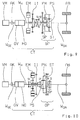
- Die hier vorliegende Erfindung betrifft einen Antriebsstrang eines Kraftfahrzeugs, insbesondere eines Nutzfahrzeugs, wobei der Antriebsstrang zumindest einen Hybridantrieb aus einem Verbrennungsmotor VM und einer elektrischen Maschine EM und ein Gruppengetriebe CT umfasst. Das Gruppengetriebe CT umfasst zumindest ein Hauptgetriebe HG und eine dem Hauptgetriebe HG antriebstechnisch nachgeschaltete Nachschaltgruppe GP, wobei die Nachschaltgruppe GP vorzugsweise als Range-Gruppe bzw. Bereichsgruppe ausgeführt ist. Im gezeigten Ausführungsbeispiel der
Fig. 1 umfasst das Gruppengetriebe CT zusätzlich noch eine dem Hauptgetriebe HG antriebstechnisch vorgeschaltete Vorschaltgruppe GV, wobei die Vorschaltgruppe GV vorzugsweise als Splitgruppe ausgeführt ist. GemäßFig. 1 ist der Verbrennungsmotor VM über eine steuerbare Anfahrkupplung AK an eine Eingangswelle WEG des Gruppengetriebes CT koppelbar. Eine Ausgangswelle WGA des Gruppengetriebes CT ist an einen Achsantrieb AB gekoppelt. - Wie bereits ausgeführt, verfügt der Antriebsstrang der
Fig. 1 neben dem Verbrennungsmotor VM über eine elektrische Maschine EM. Verbrennungsmotor VM und elektrische Maschine EM bilden zusammen einen Hybridantrieb, wobei im Sinne der hier vorliegenden Erfindung die elektrische Maschine EM des Hybridantriebs zwischen dem Hauptgetriebe HG und der Nachschaltgruppe GP und/oder zwischen der Nachschaltgruppe GP und dem Achsantrieb AB an den Kraftfluss bzw. Momentfluss des Antriebsstrangs koppelbar ist. Im Ausführungsbeispiel derFig. 1 ist die elektrische Maschine EM des Hybridantriebs permanent zwischen dem Hauptgetriebe HG und der Nachschaltgruppe GP an den Kraftfluss bzw. Momentfluss des Antriebsstrangs gekoppelt. - Beim Antriebsstrang der
Fig. 1 ist es möglich, über die elektrische Maschine EM des Hybridantriebs bei Ausführung einer Schaltung im Hauptgetriebe HG sowie bei Ausführung bei einer Schaltung in der Vorschalgruppe GV eine Zugkraftunterstützung zum Ausgleich bzw. zur Kompensation einer Zugkraftunterbrechung bereitzustellen. - Dabei wird die Nachschaltgruppe GP als Übersetzungsgetriebe für die elektrische Maschine EM des Hybridantriebs genutzt. Auf diese Art und Weise können eine Vielzahl von Hybridfunktion bereitgestellt werden, wie zum Beispiel rein elektrisches Fahren, eine Start/Stopp-Funktion für den Verbrennungsmotor VM, ein sogenanntes elektrisches Boosten sowie ein Rekuperieren.
- Das Ausfüllen bzw. Kompensieren einer Zugkraftunterbrechung durch Bereitstellen einer Zugkraftunterstützung über die elektrische Maschine EM des Hybridantriebs ist beim Antriebsstrang der
Fig. 1 bei allen Schaltungen im Hauptgetriebe HG sowie bei allen Schaltungen in der Vorschaltgruppe GV möglich. Beim Antriebsstrang derFig. 1 sind ausschließlich Schaltungen der Nachschaltgruppe GP weiterhin zugkraftunterbrochen. - Dann, wenn beim Antriebsstrang der
Fig. 1 das Hauptgetriebe HG über einen sogenannten Overdrive-Gang mit einer Übersetzung <1 verfügt, wird dann, wenn der Verbrennungsmotor VM mithilfe der elektrischen Maschine EM gestartet werden soll, im Hauptgetriebe HG dieser Overdrive-Gang eingelegt. In diesem Fall muss dann von der elektrischen Maschine EM des Hybridantriebs relativ wenig Moment zum Starten des Verbrennungsmotors VM bereitgestellt bzw. aufgebracht werden. - Ferner ist es beim Antriebsstrang der
Fig. 1 beim sogenannten Rekuperieren, also beim Bremsen mit einem Moment der elektrischen Maschine EM, möglich, im Hauptgetriebe HG einen Gang nachzuführen, und zwar bei andauernd vollem Moment der elektrischen Maschine EM. Dieses Gangnachführen ist vor allem dann von Vorteil, wenn ein Fahrer anschließend wieder Gas gibt und eine kurze Ansprechzeit auf das Gasgeben gewünscht ist. Für diesen Fall ist im Hauptgetriebe HG der für den Verbrennungsmotor VM passende Gang bereits eingelegt. - Wie bereits ausgeführt, nutzt beim Antriebsstrang der
Fig. 1 die elektrische Maschine EM des Hybridantriebs die Übersetzung der Nachschaltgruppe GP. Im Stillstand des Antriebsstrangs kann der Verbrennungsmotor VM über die elektrische Maschine EM des Antriebsstrangs gestartet werden. Ferner kann im Stillstand des Antriebsstrangs die elektrische Maschine EM generatorisch betrieben werden, um zum Beispiel einen Batterie des Antriebsstrangs zu laden oder für ein Boardnetz eine Stromversorgung bereitzustellen. Hierbei befindet sich dann die Nachschaltgruppe GP in Neutral. Bei einer Schaltung in der Nachschaltgruppe GP kann mithilfe der elektrischen Maschine EM eine Synchronisierung durchgeführt werden. - Eine vorteilhafte Weiterbildung des Ausführungsbeispiels der
Fig. 1 ist inFig. 2 gezeigt. InFig. 2 ist die elektrische Maschine EM wiederum permanent zwischen dem Hauptgetriebe HG des Gruppengetriebes CT und der Nachschaltgruppe GP des Gruppengetriebes CT an den Kraftfluss bzw. Momentfluss des Antriebsstrangs gekoppelt, und zwar gemäßFig. 2 unter Zwischenschaltung einer Übersetzungsstufe I1. Bei dieser Übersetzungsstufe I1 handelt es sich gemäßFig. 2 um eine Konstantübersetzung. Hierdurch kann beim Anfahren über die elektrische Maschine EM ein größeres Moment am Achsantrieb AB bereitgestellt werden. Beim Starten des Verbrennungsmotors VM über die elektrische Maschine EM ist weniger Moment erforderlich. Beim Starten des Verbrennungsmotors VM über die elektrische Maschine EM sind im Hauptgetriebe HG sowie in der vorzugsweise vorhandenen Vorschaltgruppe GV jeweils die höchsten Gänge eingelegt. Die Nachschaltgruppe GP befindet sich beim Starten des Verbrennungsmotors VM in Neutral. - Im Ausführungsbeispiel der
Fig. 1 und 2 ist die elektrische Maschine EM des Hybridantriebs jeweils permanent zwischen dem Hauptgetriebe HG des Gruppengetriebes CT und der Nachschaltgruppe GP desselben in den Kraftfluss bzw. Momentfluss geschaltet. - Demgegenüber zeigen
Fig. 3 bis 5 Ausführungsbeispiele der Erfindung, in welchen die elektrische Maschine EM des Hybridantriebs abhängig von der Schaltung mindestens eines Schaltelements zwischen dem Hauptgetriebe HG und der Nachschaltgruppe GP und/oder zwischen der Nachschaltgruppe GP und dem Achsantrieb AB an den Kraftfluss bzw. Momentfluss des Antriebsstrangs gekoppelt bzw. koppelbar ist. - So sind in den Ausführungsbeispielen der
Fig. 3, 4 zwei Schaltelemente S1 und S2 vorhanden, die unabhängig voneinander angesteuert werden können, wobei über das Schaltelement S1 die elektrische Maschine EM zwischen dem Hauptgetriebe HG und der Nachschaltgruppe GP an den Kraftfluss bzw. Momentfluss des Antriebsstrangs ankoppelbar ist, und wobei über das Schaltelement S2 die elektrische Maschine EM des Hybridantriebs zwischen die Nachschaltgruppe GP und dem Achsantrieb AB an den Kraftfluss bzw. Momentfluss des Antriebsstrangs ankoppelbar ist. Dann, wenn beide Schaltelemente S1 und S2 geöffnet sind, ist die elektrische Maschine EM vollständig vom Kraftfluss bzw. Momentfluss des Antriebsstrangs gekoppelt. Durch Schließen beider Schaltelemente S1 und S2 kann die elektrische Maschine EM sowohl zwischen dem Hauptgetriebe HG und der Nachschaltgruppe GP als auch zwischen der Nachschaltgruppe GP und dem Achsantrieb AB an den Kraftfluss bzw. Momentfluss des Antriebsstrangs gekoppelt werden. InFig. 4 ist wiederum zusätzlich die Übersetzungsstufe I1 vorhanden, die sowohl bei geschlossenem Schaltelement S1 als auch bei geschlossenem Schaltelement S2 wirksam ist. - Im Ausführungsbeispiel der
Fig. 5 sind die inFig. 4 als unabhängige Schaltelemente S1 und S2 ausgebildeten Schaltelemente durch ein Doppelschaltelement S1 /S2 ersetzt, welches entweder die elektrische Maschine EM unter Zwischenschaltung der Übersetzungsstufe I1 zwischen dem Hauptgetriebe HG und der Nachschaltgruppe GP oder zwischen der Nachschaltgruppe GP und dem Achsantrieb AB an den Kraftfluss bzw. Momentfluss des Antriebsstrangs ankoppelt. - Bei der in
Fig. 5 gezeigten Schaltstellung des Doppelschaltelements ist die elektrische Maschine EM vollständig vom Kraftfluss bzw. Momentfluss des Antriebsstrangs abgekoppelt. - Obwohl bei der Ausführung der Schaltelemente S1 und S2 als Doppelschaltelement gemäß
Fig. 5 die elektrische Maschine EM nicht gleichzeitig sowohl zwischen dem Hauptgetriebe HG und der Nachschaltgruppe GP als auch zwischen der Nachschaltgruppe GP und dem Achsantrieb AB an den Kraftfluss bzw. Momentfluss ankoppelbar ist, ist die Ausführung der Schaltelemente S1 und S2 als Doppelschaltelement gemäßFig. 5 bevorzugt, da diese Ausführung konstruktiv einfacher ist. - Die schaltbare Ankopplung der elektrischen Maschine EM des Hybridantriebs an den Kraftfluss bzw. Momentfluss des Antriebsstrangs gemäß
Fig. 3 bis 5 erlaubt einen besonders bevorzugten Betrieb des Antriebsstrangs. - So ist es bei den Antriebssträngen der
Fig. 3 bis 5 nicht nur möglich, bei Ausführung einer Schaltung im Hauptgetriebe HG sowie bei Ausführung einer Schaltung in der Vorschaltgruppe GV eine Zugkraftunterstützung bereitzustellen, sondern vielmehr auch bei Ausführung einer Schaltung in der Nachschaltgruppe GP. Hierzu wird so vorgegangen, dass zur Ausführung einer Schaltung in der Nachschaltgruppe GP vor Ausführung der Schaltung die elektrische Maschine EM zwischen der Nachschaltgruppe GP und dem Achsantrieb AB an den Kraftfluss bzw. Momentfluss des Antriebsstrangs angekoppelt wird und während der Ausführung an der Getriebeausgangswelle WGA angekoppelt bleibt. Hierdurch wirkt die elektrische Maschine EM bei Ausführung einer Schaltung in der Nachschaltgruppe GP permanent auf den Achsantrieb AB und kann so eine Zugkraftunterstützung für den Antriebsstrang bereitstellen. - Weiterhin kann bei den Antriebssträngen der
Fig. 3 bis 5 ein Gangnachführen beim Rekuperieren über alle Gänge erfolgen. - Dann, wenn die elektrische Maschine EM des Hybridantriebs vollständig vom Kraftfluss bzw. Momentfluss des Antriebsstrangs abgekoppelt ist, können zum Beispiel bei einer Fahrt mit konstanter Geschwindigkeit Nulllastverluste der elektrischen Maschine EM vermieden werden.
- Ferner ist bei der ganz abgekoppelten Position der elektrischen Maschine EM des Hybridantriebs dann, wenn in der elektrischen Maschine EM des Hybridantriebs ein Fehler auftritt, ein konventioneller, rein verbrennungsmotorischer Betrieb des Antriebsstrangs über den Verbrennungsmotor VM des Hybridantriebs möglich.
- Dann, wenn wie in
Fig. 3 und 4 gezeigt, die Schaltelemente S1 und S2 als unabhängige Schaltelemente ausgeführt sind, kann die elektrische Maschine EM des Hybridantriebs gleichzeitig sowohl zwischen Hauptgetriebe HG und Nachschaltgruppe GP als auch zwischen Nachschaltgruppe GP und Achsantrieb AB an den Kraftfluss bzw. Momentfluss des Antriebsstrangs angekoppelt werden, wodurch es zum Beispiel möglich ist, die Abtriebswelle bzw. Getriebeausgangswelle WGA zur Bereitstellung einer Parkbremse für den Antriebsstrang zu blockieren. - Bei den Schaltelementen S1 und S2 der Antriebsstränge der
Fig. 3 bis 5 handelt es sich vorzugsweise um Klauenschaltelemente, deren Synchronisation aktiv durch die elektrische Maschine EM erfolgt. - Die Schaltelemente S1 und S2 werden vorzugsweise pneumatisch mit Druckluft betätigt.
- Weitere vorteilhafte Ausgestaltungen und Betriebsweisen eines Antriebsstrangs mit einer elektrischen Maschine EM eines Hybridantriebs, die im Sinne der
Fig. 3 bis 5 schaltbar an den Kraftfluss bzw. Momentfluss des Antriebsstrangs zwischen Hauptgetriebe HG und Nachschaltgruppe GP und/oder zwischen Nachschaltgruppe GP und Achsantrieb AB gekoppelt werden kann, werden nachfolgend unter Bezugnahme aufFig. 6 bis 10 beschrieben, wobeiFig. 6 bis 10 solche Varianten eines erfindungsgemäßen Antriebsstrangs zeigen, in welchen die Nachschaltgruppe GP als Bereichsgruppe bzw. Range-Gruppe in Planetenbauweise ausgeführt ist. - So zeigen
Fig. 6 bis 10 jeweils eine als Range-Gruppe bzw. Bereichsgruppe ausgeführte Nachschaltgruppe GP in Planetenbauweise, wobei ein Sonnenrad PS der Nachschaltgruppe GP mit einer Hauptwelle WH des Hauptgetriebes HG gekoppelt ist, und wobei ein Steg ST der Nachschaltgruppe GP über die Ausgangswelle WGA des Gruppengetriebes GT an den Achsantrieb AB gekoppelt ist. Ein Hohlrad PH der Nachschaltgruppe GP steht mit einem Schaltpaket SP der Nachschaltgruppe GP in Verbindung, wobei das Schaltpaket SP die Nachschaltgruppe GP wechselweise durch die Verbindung des Hohlrads PH mit einem feststehenden Gehäuseteil in eine Rangefahrtstufe R oder durch Verbindung des Hohlrads PH mit der Getriebeausgangswelle WGA des Gruppengetriebes CT in eine Direktfahrtstufe D schaltet. - Weiterhin zeigen
Fig. 6 bis 10 wiederum die Schaltelemente S1 und S2, die inFig. 6 über ein Doppelschaltelement ausgeführt sind, wobei in der Schaltstellung S1 die elektrische Maschine EM zwischen Hauptgetriebe HG und Nachschaltgruppe GP an die Hauptwelle WH des Hauptgetriebes HG und damit an das Sonnenrad PS der Nachschaltgruppe GP gekoppelt ist, und wobei in der Schaltstellung S2 die elektrische Maschine EM zwischen Nachschaltgruppe GP und Achsantrieb AB über den Steg ST an die Getriebeausgangswelle WGA gekoppelt ist. - Wie bereits ausgeführt, kann bei der schaltbaren Ankopplung der elektrischen Maschine EM des Hybridantriebs an den Kraftfluss bzw. Momentfluss des Antriebsstrangs ein Gangnachführen beim Rekuperieren über alle Gänge erfolgen. Wenn sich die Nachschaltgruppe GP bereits zu Beginn des Rekuperierens in der Rangefahrtstufe R befindet, dann braucht die Nachschaltgruppe GP nicht geschaltet zu werden. Befindet sich hingegen die Nachschaltgruppe GP zu Beginn der Rekuperation in der Direktfahrtstufe D, dann muss dieselbe geschaltet werden, um einen zum Verbrennungsmotor VM passenden Gang bereitzustellen. Die elektrische Maschine EM des Hybridantriebs bleibt dann in
Fig. 6 über die Schaltstellung S2 an die Getriebeausgangswelle WGA abtriebsseitig angekoppelt und kann dann unterbrechungsfrei rekuperieren. -
Fig. 7 zeigt eine Variante der Erfindung basierend aufFig. 6 , in welcher zusätzlich die Übersetzungsstufe I1, die als Konstantübersetzung ausgeführt ist, vorhanden ist, wobei die Übersetzungsstufe I1 inFig. 7 als Planetengetriebe mit sogenannter Standgetriebeübersetzung ausgeführt ist. - Eine Alternative zur
Fig. 7 zeigtFig. 8 , wobei sichFig. 7 und 8 dadurch unterscheiden, dass inFig. 8 die Schaltelemente S1 und S2 als gemeinsames Schaltpaket realisiert sind, und dass inFig. 8 die Konstantübersetzung I1 zwischen der elektrischen Maschine EM und der Nachschaltgruppe GP positioniert ist, wohingegen inFig. 7 die Schaltelemente S1 und S2 als separate Baugruppen ausgeführt sind und die Übersetzungsstufe I1 zwischen Hauptgetriebe HG und elektrischer Maschine EM positioniert ist. -
Fig. 9 zeigt eine Abwandlung des Antriebsstrangs derFig. 8 , in welcher das Schaltpaket SP, über welches die Nachschaltgruppe GP entweder in die Rangefahrtstufe R oder die Direktfahrtstufe D schaltbar ist, nicht wie inFig. 8 gezeigt zwischen den Zahnrädern des Planetengetriebes und dem Achsantrieb AB positioniert ist, sondern vielmehr zwischen den Schaltelementen S1, S2 und den Zahnrädern des Planetengetriebes positioniert ist. - Während sich die Ausführung der
Fig. 8 vor allem für hohe Konstantübersetzungen der Übersetzungsstufe I1 eignet, eignet sich die Ausführung derFig. 9 vor allem für mittlere Konstantübersetzungen der Übersetzungsstufe I1. - Eine weitere Alternative für eine konstruktive Ausführung zeigt
Fig. 10 , wobei inFig. 10 die Schaltelemente S1 und S2 nicht durch ein gemeinsames Schaltpaket bereitgestellt sind, sondern wiederum über separate Schaltelemente, wobei inFig. 10 die Übersetzungsstufe I1 zwischen elektrischer Maschine EM und Nachschaltgruppe GP positioniert ist, und wobei inFig. 10 das Schaltpaket SP der Nachschaltgruppe GP zwischen den Zahnrädern des Planetengetriebes der Nachschaltgruppe GP und dem Achsantrieb AB positioniert ist. -
Fig. 11 zeigt eine Variante der Erfindung, in welcher die elektrische Maschine EM des Hybridantriebs permanent zwischen Hauptgetriebe HG und Nachschaltgruppe GP in den Kraftfluss bzw. Momentfluss des Antriebsstrangs geschaltet ist, wobei die Nachschaltgruppe GP in Planetenbauweise ausgeführt ist, und wobei dem Hohlrad PH der Nachschaltgruppe GP eine reibschlüssige Bremse BR zugeordnet ist. Die reibschlüssige Bremse Br, die dem Hohlrad PH der Nachschaltgruppe GP zugeordnet ist, kann dazu benutzt werden, um beim Zustart des Verbrennungsmotors VM aus einer elektrischen Fahrt heraus über eine schlupfend betriebene Bremse Br Motorschwankungen zu entkoppeln. Der Verbrennungsmotor VM wird hierbei durch Schließen der Anfahrkupplung AK gestartet, wodurch durch Motorschwankungen ein Störmoment in den Antriebsstrang eingetragen werden kann. Dieses kann über die Bremse Br kompensiert werden. - Vorzugsweise ist die schlupfende Bremse Br als trockene Bremse ausgelegt, womit bei überbrückter Nachschaltgruppe GP keine Schleppverluste an der Bremse Br auftreten.
- Die reibschlüssige Bremse Br kann weiterhin als Anfahrelement genutzt werden. So ist es möglich, ausgehend von einem generatorischen Ladebetrieb der elektrischen Maschine EM im Stillstand des Kraftfahrzeugs, in welchem sich die Nachschaltgruppe GP in Neutral befindet und in welchem im Hauptgetriebe HG und in der Vorschaltgruppe GV ein Gang eingelegt sind, bei Betätigung eines Gaspedals oder Fahrpedals über einen Fahrer, zunächst durch Aufbringen eines abstützenden Moments an der Bremse Br ein Anfahrmoment aufzubringen. Anschließend wird der Schlupf auf die Anfahrkupplung AK verlagert und die Bremse Br ganz geschlossen, da die Anfahrkupplung AK in Gegensatz zur Bremse Br konstruktiv als Anfahrelement ausgelegt ist und daher verschleißunanfälliger ist. Ferner kann bei einem Start des Verbrennungsmotors VM über eine schlupfende Anfahrkupplung AK und beim gleichzeitigen Anfahren die Bremse Br zunächst als Anfahrelement genutzt werden, wobei dann anschließend wiederum die Funktion des Anfahrelements auf die Anfahrkupplung AK verlagert und die Bremse Br vollständig geschlossen wird.
- Es sei darauf hingewiesen, dass auch in der Variante in
Fig. 11 die elektrische Maschine EM über mindestens ein Schaltelement schaltbar an den Kraftfluss bzw. Momentfluss des Antriebsstrangs ankoppelbar sein kann. -
Fig. 12 zeigt eine Weiterbildung der Variante derFig. 11 , wobei in der Variante derFig. 12 der Nachschaltgruppe GP eine reibschlüssige Überbrückungskupplung KD zusätzlich zur Bremse Br zugeordnet ist. Im Ausführungsbeispiel derFig. 12 ist die elektrische Maschine EM wiederum permanent zwischen dem Hauptgetriebe HG der Nachschaltgruppe GP an den Kraftfluss bzw. Momentfluss des Antriebsstrangs angekoppelt, wobei die elektrische Maschine EM am Sonnenrad SP der Nachschaltgruppe GP angreift. Die Bremse Br greift wiederum am Hohlrad PH der Nachschaltgruppe GP an. Die Überbrückungskupplung KD ist derart ausgeführt, dass eine erste Kupplungshälfte dem Hohlrad PH und eine zweite Kupplungshälfte dem Steg ST und damit der Getriebeausgangswelle WGA zugeordnet ist. - Durch die Verwendung der Bremse Br in Verbindung mit der Überbrückungskupplung KD ist die als Range-Gruppe bzw. Bereichsgruppe ausgeführte Nachschaltgruppe GP lastschaltbar.
- In
Fig. 12 ist möglich, bei einer Lastschaltung der Nachschaltgruppe GP das Antriebsmoment auf das Moment abzusenken, das die elektrische Maschine EM alleine erzeugen kann. Hierdurch wird die Belastung von Bremse Br und Überbrückungskupplung KD reduziert. - Im Ausführungsbeispiel der
Fig. 12 kann die elektrische Maschine EM ebenso wie bei der Variante derFig. 11 unter Zwischenanordnung einer Übersetzungsstufe 11 an den Momentfluss bzw. Kraftfluss des Antriebsstrangs gekoppelt sein. -
- AB
- Achsantrieb
- AK
- Anfahrkupplung
- Br
- Bremse
- CT
- Gruppengetriebe
- D
- Direktfahrtstufe
- EM
- elektrische Maschine
- GV
- Vorschaltgruppe
- GP
- Nachschaltgruppe
- HG
- Hauptgetriebe
- HW
- Hohlwelle
- I1
- Übersetzungsstufe
- KD
- Überbrückungskupplung
- PS
- Sonnenrad
- PT
- Planetenträger
- PH
- Hohlrad
- R
- Rangefahrtstufe
- SP
- Schaltpaket
- S1
- Schaltelement/Schaltstellung
- S2
- Schaltelement/Schaltstellung
- VM
- Verbrennungsmotor
- WGA
- Ausgangswelle
- WGE
- Eingangswelle
- WH
- Hauptwelle
Claims (11)
- Antriebsstrang eines Kraftfahrzeugs, mit einem einen Verbrennungsmotor (VM) und eine elektrische Maschine (EM) aufweisenden Hybridantrieb und einem automatisierten Gruppengetriebe (CT), wobei das automatisierte Gruppengetriebe (CT) zumindest ein Hauptgetriebe (HG) und eine dem Hauptgetriebe (HG) antriebstechnisch nachgeschaltete, insbesondere als Bereichsgruppe ausgeführte, Nachschaltgruppe (GP) aufweist, wobei eine Eingangswelle (WGE) des automatisierten Gruppengetriebes (CT) über eine steuerbare Anfahrkupplung (AK) mit dem Verbrennungsmotor (VM) des Hybridantriebs und eine Ausgangswelle (WGA) des automatisierten Gruppengetriebes (CT) mit einem Achsantrieb (AB) in Verbindung steht, wobei die elektrische Maschine (EM) des Hybridantriebs zwischen dem Hauptgetriebe (HG) und der Nachschaltgruppe (GP) und/oder zwischen der Nachschaltgruppe (GP) und dem Achsantrieb (AB) an den Kraftfluss bzw. Momentfluss des Antriebstrangs koppelbar ist, dadurch gekennzeichnet, dass die elektrische Maschine (EM) des Hybridantriebs abhängig von der Schaltstellung von mindestens zwei Schaltelementen (S1, S2) entweder ausschließlich zwischen dem Hauptgetriebe (HG) und der Nachschaltgruppe (GP) oder ausschließlich zwischen der Nachschaltgruppe (GP) und dem Achsantrieb (AB) oder sowohl zwischen dem Hauptgetriebe (HG) und der Nachschaltgruppe (GP) als auch zwischen der Nachschaltgruppe (GP) und dem Achsantrieb (AB) an den Kraftfluss bzw. Momentfluss des Antriebstrangs gekoppelt oder vom Kraftfluss bzw. Momentfluss des Antriebstrangs vollständig abgekoppelt ist.
- Antriebsstrang eines Kraftfahrzeugs, mit einem einen Verbrennungsmotor (VM) und eine elektrische Maschine (EM) aufweisenden Hybridantrieb und einem automatisierten Gruppengetriebe (CT), wobei das automatisierte Gruppengetriebe (CT) zumindest ein Hauptgetriebe (HG) und eine dem Hauptgetriebe (HG) antriebstechnisch nachgeschaltete, insbesondere als Bereichsgruppe ausgeführte, Nachschaltgruppe (GP) aufweist, wobei eine Eingangswelle (WGE) des automatisierten Gruppengetriebes (CT) über eine steuerbare Anfahrkupplung (AK) mit dem Verbrennungsmotor (VM) des Hybridantriebs und eine Ausgangswelle (WGA) des automatisierten Gruppengetriebes (CT) mit einem Achsantrieb (AB) in Verbindung steht, wobei die elektrische Maschine (EM) des Hybridantriebs zwischen dem Hauptgetriebe (HG) und der Nachschaltgruppe (GP) und/oder zwischen der Nachschaltgruppe (GP) und dem Achsantrieb (AB) an den Kraftfluss bzw. Momentfluss des Antriebstrangs koppelbar ist, dadurch gekennzeichnet, dass die elektrische Maschine (EM) des Hybridantriebs abhängig von der Schaltstellung eines als Doppelschaltelement ausgebildeten Schaltelements (S1, S2) entweder ausschließlich zwischen dem Hauptgetriebe (HG) und der Nachschaltgruppe (GP) oder ausschließlich zwischen der Nachschaltgruppe (GP) und dem Achsantrieb (AB) an den Kraftfluss bzw. Momentfluss des Antriebstrangs gekoppelt oder vom Kraftfluss bzw. Momentfluss des Antriebstrangs vollständig abgekoppelt ist.
- Antriebsstrang nach Anspruch 1 oder 2, dadurch gekennzeichnet, dass die elektrische Maschine (EM) des Hybridantriebs unter Zwischenschaltung einer Übersetzungsstufe (11) an den Kraftfluss bzw. Momentfluss des Antriebstrangs gekoppelt ist.
- Antriebsstrang nach einem der Ansprüche 1 bis 3, dadurch gekennzeichnet, dass die Nachschaltgruppe (GP) in Planetenbauweise mit einem Sonnerad (PS), einem Hohlrad (PH) und einem Steg (ST) ausgeführt ist, wobei das Sonnerad (PS) mit einer Hauptwelle (WH) des Hauptgetriebes (HG) und der Steg (ST) mit dem Achsantrieb (AB) gekoppelt ist, wobei die elektrische Maschine (EM) des Hybridantriebs dann, wenn dieselbe zwischen dem Hauptgetriebe (HG) und der Nachschaltgruppe (GP) an den Kraftfluss bzw. Momentfluss des Antriebstrangs gekoppelt ist, an das Sonnerad (PS) angebunden ist, und wobei die elektrische Maschine (EM) des Hybridantriebs dann, wenn dieselbe zwischen der Nachschaltgruppe (GP) und den Achsantrieb (AB) an den Kraftfluss bzw. Momentfluss des Antriebstrangs gekoppelt ist, an den Steg (ST) angebunden ist.
- Antriebsstrang nach Anspruch 4, dadurch gekennzeichnet, dass eine Übersetzungsstufe (l1) für die elektrische Maschine zwischen der elektrischen Maschine (EM) und der Nachschaltgruppe (GP) positioniert ist.
- Antriebsstrang nach Anspruch 4 oder 5, dadurch gekennzeichnet, dass am Hohlrad (PH) der Nachschaltgruppe (GP) eine reibschlüssige Bremse (Br) angreift.
- Antriebsstrang nach Anspruch 6, dadurch gekennzeichnet, dass der Nachschaltgruppe (GP) eine reibschlüssige Überbrückungskupplung (KD) zugeordnet ist, wobei eine erste Kupplungshälfte der Überbrückungskupplung (KD) am Hohlrad (PH) und eine zweite Kupplungshälfte der Überbrückungskupplung (KD) am Achsantrieb (AB) angreift.
- Verfahren zum Betreiben eines Antriebsstrangs nach einem der Ansprüche 1 bis 7, dadurch gekennzeichnet, dass bei Ausführung einer Schaltung im Hauptgetriebe (HG) mit der elektrische Maschine (EM) des Hybridantriebs eine Zugkraftunterbrechung am Achsantrieb (AB) kompensiert bzw. aufgefüllt wird.
- Verfahren nach Anspruch 8, dadurch gekennzeichnet, dass dann, wenn dem Hauptgetriebe (HG) antriebstechnisch eine insbesondere als Splitgruppe ausgeführte Vorschaltgruppe (GV) vorgeschaltet ist, bei Ausführung einer Schaltung in der Vorschaltgruppe (GV) mit der elektrische Maschine (EM) des Hybridantriebs eine Zugkraftunterbrechung am Achsantrieb (AB) kompensiert bzw. aufgefüllt wird.
- Verfahren nach Anspruch 8 oder 9, dadurch gekennzeichnet, dass dann, wenn das Hauptgetriebe (HG) über einen Overdrivegang mit einer Übersetzung keiner als 1 verfügt, zum Starten des Verbrennungsmotors (VM) über die elektrische Maschine (EM) des Hybridantriebs im Hauptgetriebe (HG) der Overdrivegang eingelegt wird.
- Verfahren zum Betreiben eines Antriebsstrangs nach einem der Ansprüche 1 bis 7, dadurch gekennzeichnet, dass dann, wenn in der Nachschaltgruppe (GP) eine Schaltung ausgeführt wird, vor Ausführung der Schaltung in der Nachschaltgruppe (GP) die elektrische Maschine (EM) des Hybridantriebs an den Achsantrieb (AB) angekoppelt wird und während der Ausführung der Schaltung in der Nachschaltgruppe (GP) zur Kompensation oder Auffüllung der Zugkraftunterbrechung an den Achsantrieb (AB) angekoppelt bleibt.
Applications Claiming Priority (2)
| Application Number | Priority Date | Filing Date | Title |
|---|---|---|---|
| DE102010030576A DE102010030576A1 (de) | 2010-06-28 | 2010-06-28 | Antriebsstrang mit einem automatisierten Gruppengetriebe |
| PCT/EP2011/057169 WO2012000704A1 (de) | 2010-06-28 | 2011-05-05 | Antriebsstrang mit einem automatisierten gruppengetriebe |
Publications (2)
| Publication Number | Publication Date |
|---|---|
| EP2542435A1 EP2542435A1 (de) | 2013-01-09 |
| EP2542435B1 true EP2542435B1 (de) | 2016-08-03 |
Family
ID=44121473
Family Applications (1)
| Application Number | Title | Priority Date | Filing Date |
|---|---|---|---|
| EP11718080.2A Active EP2542435B1 (de) | 2010-06-28 | 2011-05-05 | Antriebsstrang mit einem automatisierten gruppengetriebe |
Country Status (5)
| Country | Link |
|---|---|
| US (1) | US9718463B2 (de) |
| EP (1) | EP2542435B1 (de) |
| CN (1) | CN103003082B (de) |
| DE (1) | DE102010030576A1 (de) |
| WO (1) | WO2012000704A1 (de) |
Cited By (1)
| Publication number | Priority date | Publication date | Assignee | Title |
|---|---|---|---|---|
| US11407301B2 (en) | 2019-01-17 | 2022-08-09 | Aisin Corporation | Vehicle drive device |
Families Citing this family (20)
| Publication number | Priority date | Publication date | Assignee | Title |
|---|---|---|---|---|
| DE102011105521B4 (de) * | 2011-06-22 | 2016-06-23 | Getrag Getriebe- Und Zahnradfabrik Hermann Hagenmeyer Gmbh & Cie Kg | Hybrid-Antriebsstrang und Gangstufenwechselverfahren |
| DE102011106443B4 (de) * | 2011-07-04 | 2013-10-31 | Voith Patent Gmbh | Fahrzeuggetriebe |
| DE102012204956A1 (de) * | 2012-03-28 | 2013-10-02 | Robert Bosch Gmbh | Antriebsstrang mit Mehrfachkupplungsgetrieben für Hybridfahrzeuge |
| ITMI20121463A1 (it) * | 2012-08-31 | 2014-03-01 | Automobili Lamborghini Spa | Dispositivo di trazione per un autoveicolo a trazione ibrida |
| DE102012220635A1 (de) * | 2012-11-13 | 2014-05-15 | Zf Friedrichshafen Ag | Hybridisiertes Kraftfahrzeuggetriebe |
| DE102012220634A1 (de) * | 2012-11-13 | 2014-05-15 | Zf Friedrichshafen Ag | Hybridisiertes Kraftfahrzeuggetriebe |
| JP5990337B2 (ja) * | 2012-11-20 | 2016-09-14 | ボルボ コンストラクション イクイップメント アーベー | 作業機械のためのギヤボックス及びギヤボックスを制御する方法 |
| DE102012221889A1 (de) * | 2012-11-29 | 2014-06-05 | Zf Friedrichshafen Ag | Zugkraftunterstütztes Mehrgruppengetriebe |
| CN103998828B (zh) * | 2012-12-12 | 2015-08-05 | 丰田自动车株式会社 | 车辆的动力传递装置 |
| DE102013223462A1 (de) * | 2013-11-18 | 2015-05-21 | Zf Friedrichshafen Ag | Kraftfahrzeuggetriebe für einen Antriebsstrang eines Hybridfahrzeuges, sowie Antriebsstrang eines Hybridfahrzeuges |
| DE102014109169B4 (de) | 2014-07-01 | 2024-03-28 | Dr. Ing. H.C. F. Porsche Aktiengesellschaft | Automatisiertes Schaltgetriebe, Antriebsstrang und -verfahren |
| DE102014213908A1 (de) | 2014-07-17 | 2016-01-21 | Zf Friedrichshafen Ag | Getriebesystem für einen Hybridantrieb und Verfahren zum Betreiben eines Getriebesystems |
| US9732719B2 (en) * | 2014-10-31 | 2017-08-15 | Ford Global Technologies, Llc | Cold temperature engine start strategies |
| JP6801219B2 (ja) * | 2016-05-12 | 2020-12-16 | いすゞ自動車株式会社 | ハイブリッド車両 |
| JP6801220B2 (ja) * | 2016-05-12 | 2020-12-16 | いすゞ自動車株式会社 | ハイブリッド車両 |
| CN106122393A (zh) * | 2016-07-29 | 2016-11-16 | 龚小娥 | 具有倍挡功能的离合装置及变速总成 |
| DE102017005310B4 (de) * | 2017-06-02 | 2021-09-30 | Daimler Ag | Gruppengetriebe für ein Kraftfahrzeug, insbesondere für ein Nutzfahrzeug |
| GB201820881D0 (en) * | 2018-12-20 | 2019-02-06 | Agco Int Gmbh | EPowershift driveline |
| DE102020113089A1 (de) * | 2020-05-14 | 2021-11-18 | Schaeffler Technologies AG & Co. KG | Antriebseinheit für ein Hybridkraftfahrzeug mit Schaltgetriebe; sowie Verfahren zum Umschalten zwischen zwei Gängen |
| CN113895218A (zh) * | 2021-11-23 | 2022-01-07 | 合肥工业大学 | 一种主电机前后置可切换式构型及设有其的混合动力汽车 |
Family Cites Families (14)
| Publication number | Priority date | Publication date | Assignee | Title |
|---|---|---|---|---|
| JP3454036B2 (ja) * | 1995-11-13 | 2003-10-06 | トヨタ自動車株式会社 | ハイブリッド駆動装置 |
| DE19962854A1 (de) * | 1999-01-17 | 2001-07-05 | Boisch Richard | Automatisiertes Lastschaltgetriebe für Kraftfahrzeuge mit Synchronisationseinrichtung |
| US6540631B2 (en) * | 2001-08-13 | 2003-04-01 | General Motors Corporation | Electrically variable transmission with variable input power split and independent shifting |
| DE10152477A1 (de) * | 2001-10-24 | 2003-05-08 | Zahnradfabrik Friedrichshafen | Schaltgetriebe |
| DE10315683A1 (de) * | 2003-04-07 | 2004-10-21 | Zf Friedrichshafen Ag | Elektrodynamisches Antriebssystem |
| DE102004031463A1 (de) | 2004-06-28 | 2006-01-19 | Entwicklungsgesellschaft für Getriebesysteme bmH | Lastschaltgetriebe |
| DE102006006623A1 (de) * | 2006-02-14 | 2007-09-20 | Zf Friedrichshafen Ag | Mehrstufengetriebe |
| DE102007005525A1 (de) * | 2007-02-03 | 2008-08-07 | Zf Friedrichshafen Ag | Getriebevorrichtung und Verfahren zum Betreiben einer Getriebevorrichtung |
| DE102007007257A1 (de) * | 2007-02-14 | 2008-08-21 | Zf Friedrichshafen Ag | Verfahren zum Betreiben eines Antriebsstranges eines Fahrzeuges |
| DE102007010829A1 (de) | 2007-03-06 | 2008-09-11 | Zf Friedrichshafen Ag | Verfahren zur Schaltsteuerung eines automatisierten Gruppengetriebes |
| DE102008002380A1 (de) * | 2008-06-12 | 2009-12-17 | Zf Friedrichshafen Ag | Getriebe in Vorgelegebauweise und Verfahren zum Betreiben des Getriebes |
| DE102009000710A1 (de) * | 2009-02-09 | 2010-08-12 | Zf Friedrichshafen Ag | Verfahren zur Schaltsteuerung eines automatisierten Gruppengetriebes und automatisiertes Gruppengetriebe eines Kraftfahrzeuges |
| DE102009054752A1 (de) * | 2009-12-16 | 2011-06-22 | ZF Friedrichshafen AG, 88046 | Antriebsstrang mit einem automatisierten Gruppengetriebe |
| DE102010030575A1 (de) * | 2010-06-28 | 2011-12-29 | Zf Friedrichshafen Ag | Antriebsstrang mit einem automatisierten Gruppengetriebe |
-
2010
- 2010-06-28 DE DE102010030576A patent/DE102010030576A1/de not_active Withdrawn
-
2011
- 2011-05-05 WO PCT/EP2011/057169 patent/WO2012000704A1/de not_active Ceased
- 2011-05-05 EP EP11718080.2A patent/EP2542435B1/de active Active
- 2011-05-05 US US13/806,627 patent/US9718463B2/en active Active
- 2011-05-05 CN CN201180032023.5A patent/CN103003082B/zh active Active
Cited By (1)
| Publication number | Priority date | Publication date | Assignee | Title |
|---|---|---|---|---|
| US11407301B2 (en) | 2019-01-17 | 2022-08-09 | Aisin Corporation | Vehicle drive device |
Also Published As
| Publication number | Publication date |
|---|---|
| US20130217537A1 (en) | 2013-08-22 |
| DE102010030576A1 (de) | 2011-12-29 |
| CN103003082B (zh) | 2016-07-13 |
| EP2542435A1 (de) | 2013-01-09 |
| CN103003082A (zh) | 2013-03-27 |
| US9718463B2 (en) | 2017-08-01 |
| WO2012000704A1 (de) | 2012-01-05 |
Similar Documents
| Publication | Publication Date | Title |
|---|---|---|
| EP2542435B1 (de) | Antriebsstrang mit einem automatisierten gruppengetriebe | |
| EP2737230B1 (de) | Automatisiertes gruppengetriebe eines kraftfahrzeugs und verfahren zum betreiben desselben | |
| EP2369203B1 (de) | Verfahren zum Betreiben eines Antriebsstrangs | |
| DE102009054752A1 (de) | Antriebsstrang mit einem automatisierten Gruppengetriebe | |
| DE102011080068A1 (de) | Automatisiertes Gruppengetriebe eines Kraftfahrzeugs und Verfahren zum Betreiben desselben | |
| DE102012218367A1 (de) | Gruppengetriebevorrichtung mit einer elektrischen Maschine | |
| EP2738030A2 (de) | Zugkraftunterstütztes Mehrgruppengetriebe und Verfahren zu dessen Betreiben | |
| WO2009024162A1 (de) | Hybridantriebssystem mit zwei teilgetrieben | |
| DE102010002724A1 (de) | Verfahren zum Betreiben eines Antriebsstrangs | |
| DE102010030575A1 (de) | Antriebsstrang mit einem automatisierten Gruppengetriebe | |
| DE102020205099A1 (de) | Getriebeanordnung, Hybrid-Antriebsstrang sowie Kraftfahrzeug | |
| DE102011089466A1 (de) | Hybridantrieb eines Kraftfahrzeugs und Verfahren zum Betreiben desselben | |
| DE102021203414B4 (de) | Gangvorwahlfrei lastschaltbares Hybridgetriebe | |
| DE102021213667A1 (de) | Viergang-Hybridgetriebe in Mischbauweise | |
| DE102021206522A1 (de) | Kompaktes Hybridgetriebe mit mechanischem einfachem Aufbau | |
| DE102021211236B4 (de) | Kompaktes Hybridgetriebe in Planetenbauweise | |
| DE102022203688A1 (de) | Kompaktes Hybridgetriebe | |
| DE102021206520A1 (de) | Gangvorwahlfrei lastschaltbares Hybridgetriebe mit einfachem Aufbau | |
| DE102021206516A1 (de) | Gangvorwahlfrei lastschaltbares Vier-Gang Hybridgetriebe | |
| DE102021209702B4 (de) | Hybrid-Antriebsstrang in Mischbauweise | |
| DE102020214533A1 (de) | Hybridgetriebe mit elektrischer Zugkraftunterstützung | |
| DE102022209067B4 (de) | Hybrid-Antriebsstrang mit zwei Vorgelegewellen | |
| DE102020203803A1 (de) | Hybridgetriebe mit elektrischer Zugkraftunterstützung | |
| DE102021213652B4 (de) | Viergang-Hybridgetriebe | |
| DE102022206207B4 (de) | Kompakter Hybrid-Antriebsstrang |
Legal Events
| Date | Code | Title | Description |
|---|---|---|---|
| PUAI | Public reference made under article 153(3) epc to a published international application that has entered the european phase |
Free format text: ORIGINAL CODE: 0009012 |
|
| 17P | Request for examination filed |
Effective date: 20120927 |
|
| AK | Designated contracting states |
Kind code of ref document: A1 Designated state(s): AL AT BE BG CH CY CZ DE DK EE ES FI FR GB GR HR HU IE IS IT LI LT LU LV MC MK MT NL NO PL PT RO RS SE SI SK SM TR |
|
| DAX | Request for extension of the european patent (deleted) | ||
| GRAP | Despatch of communication of intention to grant a patent |
Free format text: ORIGINAL CODE: EPIDOSNIGR1 |
|
| INTG | Intention to grant announced |
Effective date: 20160309 |
|
| GRAS | Grant fee paid |
Free format text: ORIGINAL CODE: EPIDOSNIGR3 |
|
| GRAA | (expected) grant |
Free format text: ORIGINAL CODE: 0009210 |
|
| AK | Designated contracting states |
Kind code of ref document: B1 Designated state(s): AL AT BE BG CH CY CZ DE DK EE ES FI FR GB GR HR HU IE IS IT LI LT LU LV MC MK MT NL NO PL PT RO RS SE SI SK SM TR |
|
| REG | Reference to a national code |
Ref country code: GB Ref legal event code: FG4D Free format text: NOT ENGLISH |
|
| REG | Reference to a national code |
Ref country code: CH Ref legal event code: EP Ref country code: AT Ref legal event code: REF Ref document number: 817092 Country of ref document: AT Kind code of ref document: T Effective date: 20160815 |
|
| REG | Reference to a national code |
Ref country code: IE Ref legal event code: FG4D Free format text: LANGUAGE OF EP DOCUMENT: GERMAN |
|
| REG | Reference to a national code |
Ref country code: DE Ref legal event code: R096 Ref document number: 502011010309 Country of ref document: DE |
|
| REG | Reference to a national code |
Ref country code: NL Ref legal event code: MP Effective date: 20160803 |
|
| REG | Reference to a national code |
Ref country code: LT Ref legal event code: MG4D |
|
| PG25 | Lapsed in a contracting state [announced via postgrant information from national office to epo] |
Ref country code: IT Free format text: LAPSE BECAUSE OF FAILURE TO SUBMIT A TRANSLATION OF THE DESCRIPTION OR TO PAY THE FEE WITHIN THE PRESCRIBED TIME-LIMIT Effective date: 20160803 Ref country code: RS Free format text: LAPSE BECAUSE OF FAILURE TO SUBMIT A TRANSLATION OF THE DESCRIPTION OR TO PAY THE FEE WITHIN THE PRESCRIBED TIME-LIMIT Effective date: 20160803 Ref country code: NL Free format text: LAPSE BECAUSE OF FAILURE TO SUBMIT A TRANSLATION OF THE DESCRIPTION OR TO PAY THE FEE WITHIN THE PRESCRIBED TIME-LIMIT Effective date: 20160803 Ref country code: NO Free format text: LAPSE BECAUSE OF FAILURE TO SUBMIT A TRANSLATION OF THE DESCRIPTION OR TO PAY THE FEE WITHIN THE PRESCRIBED TIME-LIMIT Effective date: 20161103 Ref country code: IS Free format text: LAPSE BECAUSE OF FAILURE TO SUBMIT A TRANSLATION OF THE DESCRIPTION OR TO PAY THE FEE WITHIN THE PRESCRIBED TIME-LIMIT Effective date: 20161203 Ref country code: LT Free format text: LAPSE BECAUSE OF FAILURE TO SUBMIT A TRANSLATION OF THE DESCRIPTION OR TO PAY THE FEE WITHIN THE PRESCRIBED TIME-LIMIT Effective date: 20160803 Ref country code: HR Free format text: LAPSE BECAUSE OF FAILURE TO SUBMIT A TRANSLATION OF THE DESCRIPTION OR TO PAY THE FEE WITHIN THE PRESCRIBED TIME-LIMIT Effective date: 20160803 Ref country code: FI Free format text: LAPSE BECAUSE OF FAILURE TO SUBMIT A TRANSLATION OF THE DESCRIPTION OR TO PAY THE FEE WITHIN THE PRESCRIBED TIME-LIMIT Effective date: 20160803 |
|
| PG25 | Lapsed in a contracting state [announced via postgrant information from national office to epo] |
Ref country code: PL Free format text: LAPSE BECAUSE OF FAILURE TO SUBMIT A TRANSLATION OF THE DESCRIPTION OR TO PAY THE FEE WITHIN THE PRESCRIBED TIME-LIMIT Effective date: 20160803 Ref country code: SE Free format text: LAPSE BECAUSE OF FAILURE TO SUBMIT A TRANSLATION OF THE DESCRIPTION OR TO PAY THE FEE WITHIN THE PRESCRIBED TIME-LIMIT Effective date: 20160803 Ref country code: LV Free format text: LAPSE BECAUSE OF FAILURE TO SUBMIT A TRANSLATION OF THE DESCRIPTION OR TO PAY THE FEE WITHIN THE PRESCRIBED TIME-LIMIT Effective date: 20160803 Ref country code: GR Free format text: LAPSE BECAUSE OF FAILURE TO SUBMIT A TRANSLATION OF THE DESCRIPTION OR TO PAY THE FEE WITHIN THE PRESCRIBED TIME-LIMIT Effective date: 20161104 Ref country code: PT Free format text: LAPSE BECAUSE OF FAILURE TO SUBMIT A TRANSLATION OF THE DESCRIPTION OR TO PAY THE FEE WITHIN THE PRESCRIBED TIME-LIMIT Effective date: 20161205 Ref country code: ES Free format text: LAPSE BECAUSE OF FAILURE TO SUBMIT A TRANSLATION OF THE DESCRIPTION OR TO PAY THE FEE WITHIN THE PRESCRIBED TIME-LIMIT Effective date: 20160803 |
|
| PG25 | Lapsed in a contracting state [announced via postgrant information from national office to epo] |
Ref country code: EE Free format text: LAPSE BECAUSE OF FAILURE TO SUBMIT A TRANSLATION OF THE DESCRIPTION OR TO PAY THE FEE WITHIN THE PRESCRIBED TIME-LIMIT Effective date: 20160803 Ref country code: RO Free format text: LAPSE BECAUSE OF FAILURE TO SUBMIT A TRANSLATION OF THE DESCRIPTION OR TO PAY THE FEE WITHIN THE PRESCRIBED TIME-LIMIT Effective date: 20160803 |
|
| REG | Reference to a national code |
Ref country code: DE Ref legal event code: R097 Ref document number: 502011010309 Country of ref document: DE |
|
| PG25 | Lapsed in a contracting state [announced via postgrant information from national office to epo] |
Ref country code: CZ Free format text: LAPSE BECAUSE OF FAILURE TO SUBMIT A TRANSLATION OF THE DESCRIPTION OR TO PAY THE FEE WITHIN THE PRESCRIBED TIME-LIMIT Effective date: 20160803 Ref country code: DK Free format text: LAPSE BECAUSE OF FAILURE TO SUBMIT A TRANSLATION OF THE DESCRIPTION OR TO PAY THE FEE WITHIN THE PRESCRIBED TIME-LIMIT Effective date: 20160803 Ref country code: SM Free format text: LAPSE BECAUSE OF FAILURE TO SUBMIT A TRANSLATION OF THE DESCRIPTION OR TO PAY THE FEE WITHIN THE PRESCRIBED TIME-LIMIT Effective date: 20160803 Ref country code: BG Free format text: LAPSE BECAUSE OF FAILURE TO SUBMIT A TRANSLATION OF THE DESCRIPTION OR TO PAY THE FEE WITHIN THE PRESCRIBED TIME-LIMIT Effective date: 20161103 Ref country code: SK Free format text: LAPSE BECAUSE OF FAILURE TO SUBMIT A TRANSLATION OF THE DESCRIPTION OR TO PAY THE FEE WITHIN THE PRESCRIBED TIME-LIMIT Effective date: 20160803 |
|
| PLBE | No opposition filed within time limit |
Free format text: ORIGINAL CODE: 0009261 |
|
| STAA | Information on the status of an ep patent application or granted ep patent |
Free format text: STATUS: NO OPPOSITION FILED WITHIN TIME LIMIT |
|
| 26N | No opposition filed |
Effective date: 20170504 |
|
| PG25 | Lapsed in a contracting state [announced via postgrant information from national office to epo] |
Ref country code: SI Free format text: LAPSE BECAUSE OF FAILURE TO SUBMIT A TRANSLATION OF THE DESCRIPTION OR TO PAY THE FEE WITHIN THE PRESCRIBED TIME-LIMIT Effective date: 20160803 Ref country code: LU Free format text: LAPSE BECAUSE OF NON-PAYMENT OF DUE FEES Effective date: 20170531 |
|
| REG | Reference to a national code |
Ref country code: CH Ref legal event code: PL |
|
| GBPC | Gb: european patent ceased through non-payment of renewal fee |
Effective date: 20170505 |
|
| PG25 | Lapsed in a contracting state [announced via postgrant information from national office to epo] |
Ref country code: MC Free format text: LAPSE BECAUSE OF FAILURE TO SUBMIT A TRANSLATION OF THE DESCRIPTION OR TO PAY THE FEE WITHIN THE PRESCRIBED TIME-LIMIT Effective date: 20160803 |
|
| REG | Reference to a national code |
Ref country code: IE Ref legal event code: MM4A |
|
| PG25 | Lapsed in a contracting state [announced via postgrant information from national office to epo] |
Ref country code: LI Free format text: LAPSE BECAUSE OF NON-PAYMENT OF DUE FEES Effective date: 20170531 Ref country code: CH Free format text: LAPSE BECAUSE OF NON-PAYMENT OF DUE FEES Effective date: 20170531 |
|
| REG | Reference to a national code |
Ref country code: FR Ref legal event code: ST Effective date: 20180131 |
|
| PG25 | Lapsed in a contracting state [announced via postgrant information from national office to epo] |
Ref country code: LU Free format text: LAPSE BECAUSE OF NON-PAYMENT OF DUE FEES Effective date: 20170505 |
|
| REG | Reference to a national code |
Ref country code: BE Ref legal event code: MM Effective date: 20170531 |
|
| PG25 | Lapsed in a contracting state [announced via postgrant information from national office to epo] |
Ref country code: GB Free format text: LAPSE BECAUSE OF NON-PAYMENT OF DUE FEES Effective date: 20170505 Ref country code: IE Free format text: LAPSE BECAUSE OF NON-PAYMENT OF DUE FEES Effective date: 20170505 |
|
| PG25 | Lapsed in a contracting state [announced via postgrant information from national office to epo] |
Ref country code: FR Free format text: LAPSE BECAUSE OF NON-PAYMENT OF DUE FEES Effective date: 20170531 |
|
| REG | Reference to a national code |
Ref country code: AT Ref legal event code: MM01 Ref document number: 817092 Country of ref document: AT Kind code of ref document: T Effective date: 20170505 |
|
| PG25 | Lapsed in a contracting state [announced via postgrant information from national office to epo] |
Ref country code: AT Free format text: LAPSE BECAUSE OF NON-PAYMENT OF DUE FEES Effective date: 20170505 Ref country code: BE Free format text: LAPSE BECAUSE OF NON-PAYMENT OF DUE FEES Effective date: 20170531 |
|
| PG25 | Lapsed in a contracting state [announced via postgrant information from national office to epo] |
Ref country code: MT Free format text: LAPSE BECAUSE OF FAILURE TO SUBMIT A TRANSLATION OF THE DESCRIPTION OR TO PAY THE FEE WITHIN THE PRESCRIBED TIME-LIMIT Effective date: 20160803 |
|
| PG25 | Lapsed in a contracting state [announced via postgrant information from national office to epo] |
Ref country code: AL Free format text: LAPSE BECAUSE OF FAILURE TO SUBMIT A TRANSLATION OF THE DESCRIPTION OR TO PAY THE FEE WITHIN THE PRESCRIBED TIME-LIMIT Effective date: 20160803 |
|
| RIC2 | Information provided on ipc code assigned after grant |
Ipc: B60W 10/10 20120101ALI20120117BHEP Ipc: B60K 6/547 20071001ALI20120117BHEP Ipc: F16H 61/70 20060101ALI20120117BHEP Ipc: B60W 20/00 20160101ALI20120117BHEP Ipc: B60K 6/48 20071001ALI20120117BHEP Ipc: B60W 10/08 20060101ALI20120117BHEP Ipc: F16H 61/04 20060101ALI20120117BHEP Ipc: B60K 6/387 20071001AFI20120117BHEP Ipc: B60W 30/18 20120101ALI20120117BHEP Ipc: F16H 37/04 20060101ALI20120117BHEP |
|
| PG25 | Lapsed in a contracting state [announced via postgrant information from national office to epo] |
Ref country code: HU Free format text: LAPSE BECAUSE OF FAILURE TO SUBMIT A TRANSLATION OF THE DESCRIPTION OR TO PAY THE FEE WITHIN THE PRESCRIBED TIME-LIMIT; INVALID AB INITIO Effective date: 20110505 |
|
| PG25 | Lapsed in a contracting state [announced via postgrant information from national office to epo] |
Ref country code: CY Free format text: LAPSE BECAUSE OF NON-PAYMENT OF DUE FEES Effective date: 20160803 |
|
| PG25 | Lapsed in a contracting state [announced via postgrant information from national office to epo] |
Ref country code: MK Free format text: LAPSE BECAUSE OF FAILURE TO SUBMIT A TRANSLATION OF THE DESCRIPTION OR TO PAY THE FEE WITHIN THE PRESCRIBED TIME-LIMIT Effective date: 20160803 |
|
| PG25 | Lapsed in a contracting state [announced via postgrant information from national office to epo] |
Ref country code: TR Free format text: LAPSE BECAUSE OF FAILURE TO SUBMIT A TRANSLATION OF THE DESCRIPTION OR TO PAY THE FEE WITHIN THE PRESCRIBED TIME-LIMIT Effective date: 20160803 |
|
| REG | Reference to a national code |
Ref country code: DE Ref legal event code: R084 Ref document number: 502011010309 Country of ref document: DE |
|
| P01 | Opt-out of the competence of the unified patent court (upc) registered |
Effective date: 20230528 |
|
| PGFP | Annual fee paid to national office [announced via postgrant information from national office to epo] |
Ref country code: DE Payment date: 20250311 Year of fee payment: 15 |