EP2542477B1 - Étiqueteuse et procédé associé - Google Patents
Étiqueteuse et procédé associé Download PDFInfo
- Publication number
- EP2542477B1 EP2542477B1 EP10717290.0A EP10717290A EP2542477B1 EP 2542477 B1 EP2542477 B1 EP 2542477B1 EP 10717290 A EP10717290 A EP 10717290A EP 2542477 B1 EP2542477 B1 EP 2542477B1
- Authority
- EP
- European Patent Office
- Prior art keywords
- label
- labels
- marking
- unit
- mark
- Prior art date
- Legal status (The legal status is an assumption and is not a legal conclusion. Google has not performed a legal analysis and makes no representation as to the accuracy of the status listed.)
- Not-in-force
Links
- 238000002372 labelling Methods 0.000 title claims description 40
- 238000000034 method Methods 0.000 title claims description 18
- 238000007789 sealing Methods 0.000 claims description 11
- 238000011144 upstream manufacturing Methods 0.000 claims description 5
- 238000005452 bending Methods 0.000 claims 2
- 238000004804 winding Methods 0.000 description 26
- 238000012546 transfer Methods 0.000 description 15
- 230000007257 malfunction Effects 0.000 description 7
- 238000003466 welding Methods 0.000 description 6
- 238000003780 insertion Methods 0.000 description 5
- 230000037431 insertion Effects 0.000 description 5
- 230000008569 process Effects 0.000 description 5
- 238000005520 cutting process Methods 0.000 description 4
- 238000012423 maintenance Methods 0.000 description 4
- 238000004026 adhesive bonding Methods 0.000 description 3
- 230000004913 activation Effects 0.000 description 2
- 230000015572 biosynthetic process Effects 0.000 description 2
- 238000004519 manufacturing process Methods 0.000 description 2
- 230000002093 peripheral effect Effects 0.000 description 2
- 230000000717 retained effect Effects 0.000 description 2
- 229920006257 Heat-shrinkable film Polymers 0.000 description 1
- 230000009471 action Effects 0.000 description 1
- 235000013361 beverage Nutrition 0.000 description 1
- 230000009849 deactivation Effects 0.000 description 1
- 238000013461 design Methods 0.000 description 1
- 238000001514 detection method Methods 0.000 description 1
- 238000006073 displacement reaction Methods 0.000 description 1
- 238000010380 label transfer Methods 0.000 description 1
- ORQBXQOJMQIAOY-UHFFFAOYSA-N nobelium Chemical compound [No] ORQBXQOJMQIAOY-UHFFFAOYSA-N 0.000 description 1
- 230000000750 progressive effect Effects 0.000 description 1
- 230000000306 recurrent effect Effects 0.000 description 1
- 231100000027 toxicology Toxicity 0.000 description 1
- 238000002604 ultrasonography Methods 0.000 description 1
Images


Classifications
-
- B—PERFORMING OPERATIONS; TRANSPORTING
- B65—CONVEYING; PACKING; STORING; HANDLING THIN OR FILAMENTARY MATERIAL
- B65C—LABELLING OR TAGGING MACHINES, APPARATUS, OR PROCESSES
- B65C9/00—Details of labelling machines or apparatus
- B65C9/46—Applying date marks, code marks, or the like, to the label during labelling
-
- B—PERFORMING OPERATIONS; TRANSPORTING
- B65—CONVEYING; PACKING; STORING; HANDLING THIN OR FILAMENTARY MATERIAL
- B65C—LABELLING OR TAGGING MACHINES, APPARATUS, OR PROCESSES
- B65C9/00—Details of labelling machines or apparatus
- B65C9/40—Controls; Safety devices
-
- Y—GENERAL TAGGING OF NEW TECHNOLOGICAL DEVELOPMENTS; GENERAL TAGGING OF CROSS-SECTIONAL TECHNOLOGIES SPANNING OVER SEVERAL SECTIONS OF THE IPC; TECHNICAL SUBJECTS COVERED BY FORMER USPC CROSS-REFERENCE ART COLLECTIONS [XRACs] AND DIGESTS
- Y10—TECHNICAL SUBJECTS COVERED BY FORMER USPC
- Y10T—TECHNICAL SUBJECTS COVERED BY FORMER US CLASSIFICATION
- Y10T156/00—Adhesive bonding and miscellaneous chemical manufacture
- Y10T156/17—Surface bonding means and/or assemblymeans with work feeding or handling means
- Y10T156/1702—For plural parts or plural areas of single part
- Y10T156/1744—Means bringing discrete articles into assembled relationship
- Y10T156/1768—Means simultaneously conveying plural articles from a single source and serially presenting them to an assembly station
- Y10T156/1771—Turret or rotary drum-type conveyor
Definitions
- the present invention relates to a labelling machine, in particular a labelling machine of the type forming, e.g. from a heat-shrinkable film, and applying tubular labels to respective articles, such as bottles or generic containers.
- a labelling machine in particular a labelling machine of the type forming, e.g. from a heat-shrinkable film, and applying tubular labels to respective articles, such as bottles or generic containers.
- the following description will refer to this type of labelling machine, although this is in no way intended to limit the scope of protection as defined by the accompanying claims.
- the present invention also relates to a method for performing the above-mentioned operations.
- labelling machines are used to apply labels to containers of all sort.
- containers of all sort Typically used with beverage bottles or vessels are tubular labels (commonly called “sleeve labels”), which are obtainable by:
- a particular type of labelling machine in which a tubular label is formed on a relative cylindrical winding body (commonly called “sleeve drum”), from which it is subsequently transferred onto a relative container, for instance through insertion of the latter within the tubular label.
- a relative cylindrical winding body commonly called “sleeve drum”
- This type of labelling machine basically comprises a carousel rotating about a vertical axis and defining a circular path, along which a succession of unlabelled containers and a succession of rectangular or square labels from respective input wheels are fed to the carousel.
- the labelling machine shapes the labels in a tubular configuration and applies them onto the respective containers. Finally, the labelling machine releases the labelled containers to an output wheel.
- the carousel comprises a number of operating units which are equally spaced about the rotation axis, are mounted along a peripheral edge of the carousel and are moved by the latter along the above-mentioned circular path.
- Each labelling unit comprises a bottom supporting assembly adapted to support the bottom wall of a relative container and an upper retainer adapted to cooperate with the top portion of such container to hold it in a vertical position during the rotation of the carousel about the vertical axis.
- Each supporting assembly comprises a vertical hollow supporting mount, secured to a horizontal plane of a rotary frame of the carousel, and a cylindrical winding body, engaging the supporting mount in sliding and rotating manner with respect to its axis, and adapted to carry a relative container on its top surface and a relative label on its lateral surface.
- Each winding body is movable, under the control of cam means, between a raised position and a fully retracted position within the relative supporting mount.
- each winding body protrudes from a top surface of the relative supporting mount and is adapted to receive a relative label on its lateral surface from the label input wheel; in particular, the label is wrapped around the winding body such that the opposite vertical edges of the label overlap each other.
- each winding body In the fully retracted position, which is reached at the container input and output wheels, the top surface of each winding body is flush with the top surface of the supporting mount, so that containers are transferred onto and from the carousel along the same transfer plane.
- a number of different techniques may be used for sealing the overlapping edges of the tubular labels, e.g. ultrasound welding, as shown in the International Patent Application No. WO 2005/085073 .
- the labelled container is then generally fed to a shrinking tunnel (known per se and not shown), where shrinking and adhesion of the label to the external surface of the container is attained.
- a shrinking tunnel known per se and not shown
- the function of a label applied on a container is not merely informative.
- the label is not solely intended to bear information concerning the content of the container (e.g . composition, volume content, safety or toxicology data, best-before date and the like) but, possibly through the association with a specific design or trademark which customers have become well-acquainted and familiar with, it contributes to the recognisability of the product and, consequently, to its marketability and commercial success.
- labelling machines of the type described above generally form part of plants having a very high throughput, hence the number of tubular labels formed and applied per hour by a single labelling machine may be in the range 24,000-32,000.
- labelling machines of the type described above may further comprise a discarding station at which the labelled containers which do not meet the desired quality specifications are identified and, consequently, rejected.
- the discarding machine may be arranged immediately downstream from the carousel and, therefore, upstream from the shrinking tunnel, or, alternatively, downstream from the shrinking tunnel itself. Smaller anomalies and flaws which are not easily detectable prior to the shrinking process shall generally become evident following the application of heat which triggers the shrinking, hence this arrangement may be preferable.
- DE 3110400A1 discloses a labelling machine as defined in the preamble of claim 1.
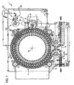
- Number 1 in Figure 1 indicates as a whole a labelling machine for applying labels 2 (see Figure 2 ) to respective articles or, more specifically, containers, particularly bottles 3, each of which ( Figures 1 and 2 ) has a given longitudinal axis A, is bonded at the bottom by a bottom wall 4 substantially perpendicular to axis A, and has a top neck 5 substantially coaxial with axis A.
- Machine 1 comprises a conveying device that serves to bend and seal (weld) labels 2 in a tubular configuration (details not shown) and to produce insertion of bottles 3 into the so formed tubular labels 2.
- the conveying device comprises a carousel 7, which is mounted to rotate continuously (anticlockwise in Figure 1 ) about a respective vertical axis B perpendicular to the plane of Figure 1 .
- the carousel 7 receives a succession of unlabelled bottles 3 from an input wheel 8, which cooperates with carousel 7 at a first transfer station 9 and is mounted to rotate continuously about a respective longitudinal axis C parallel to axis B.
- the carousel 7 also receives a succession of rectangular or square labels 2 from an input drum 10, which cooperates with carousel 7 at a second transfer station 11 and is mounted to rotate continuously about a respective longitudinal axis D parallel to axes B and C.
- the carousel 7 releases a succession of labelled bottles 3 to an output wheel 12, which cooperates with carousel 7 at a third transfer station 13 and is mounted to rotate continuously about a respective longitudinal axis E parallel to axes B, C and D.
- the carousel 7 comprises a number of operating units 15, which are equally spaced about axis B, are mounted along a peripheral edge of carousel 7, and are moved by carousel 7 along a circular path P extending about axis B and through transfer station 9, 11 and 13.
- transfer station 11 is arranged, along path P, downstream from transfer station 9 and upstream from transfer station 13.
- each unit 15 comprises a conveying module 16 adapted to receive a relative bottle 3 from input wheel 8 in a. vertical position, i.e. with the relative axis A parallel to axes B, C, D, and to hold said bottle 3 in such position along path P from transfer station 9 to transfer station 13.
- Each conveying module 16 comprises a bottom supporting assembly 17 adapted to support the bottom wall 4 of a relative bottle 3 and an upper retainer 18 adapted to cooperate with the top neck 5 of the bottle 3.
- each supporting assembly 17 comprises:
- each winding body 22 can be moved along axis F in a known manner, under the control of cam means (not shown), between a fully retracted position within the relative supporting mount 20 (not shown) and a raised position (Figure).
- each winding body 22 is completely housed within the relative supporting mount 20 so that its top surface 23 is flush with a top surface 25 of the supporting mount 20.
- each winding body 22 protrudes from the top surface 25 of the relative supporting mount 20 and is adapted to receive, on its lateral surface 24, a relative label 2 from input drum 10.
- labels 2 are cut in a know manner from a web 26 ( Figure 1 ) by a cutting device 27 (only schematically shown in Figure 1 ) and fed to input drum 10 to be then transferred to the relative winding bodies 22.
- the labelling machine 1 comprises a marking unit 100 for marking the surface of each label 2 with a mark M.
- the marking unit 100 is arranged, along path P, upstream from the cutting device 27.
- marking unit 100 comprises (see Figure 3 ) means 101 for marking the surface of a label 2, such as a write head or a laser system and a support element 102, by which the marking means are supported.
- the marking means 101 are arranged such as to mark the surface of labels 2 on the side which shall be applied onto containers 3 (see Figure 2 ).
- the marking unit 100 marks the surface of each label 2 with a distinctive mark univocally associable with the corresponding operating unit 15 by which said label 2 shall be received and processed (i.e. formed into a tubular label, applied to a container, etc.).
- the marking unit 100 may print on the surface of each label 2 to be fed to a certain operating unit 15 a number univocally corresponding to that specific operating unit 15.
- the distinctive sign may be a bar-code, a single letter or a combination of letters, etc., provided that a one-to-one correspondence between each mark employed and a single specific operating unit 15 is predetermined and consistently stuck by.
- the one-to-one correspondence is acquired and set during a first cycle of operation of the labelling machine 1.
- the marking means 101 mark the surface of a first plurality of labels with a corresponding plurality of distinct marks, each being at once associated with a corresponding operating unit 15.
- the marking means may mark the labels 3 with progressive numbers from one to N, where N is the overall number of operating units 15 borne by the carousel 7.
- the marking unit 100 may advantageously comprise a controller 103 operatively connected with the marking means 101 and the carousel 7 and programmed for managing the operation of the marking means 101 so that they correctly and consistently mark the surface of each label 2 with a distinctive mark univocally associated with the corresponding operating unit 15 by which said label 2 shall be, downstream from the marking unit 100, received and processed.
- a controller 103 operatively connected with the marking means 101 and the carousel 7 and programmed for managing the operation of the marking means 101 so that they correctly and consistently mark the surface of each label 2 with a distinctive mark univocally associated with the corresponding operating unit 15 by which said label 2 shall be, downstream from the marking unit 100, received and processed.
- controller 103 is programmed to receive information concerning the advance sequence of the operating units 15 and of the labels 2 along the path P and to accordingly actuate the marking means 101, so that, in operation, a predetermined one-to-one correspondence between each mark employed and a single specific operating unit 15 is consistently stuck by.
- the cut and marked labels 2 are retained on a lateral surface 30 of the input drum 10 by suction; in fact, the lateral surface 30 of the input drum 10 is divided into a given number of suction regions, which are equally spaced about axis D, are each provided with a plurality of through holes 32 connected to a pneumatic suction device (known per se and not shown) and are adapted to cooperate with respective labels 2.
- a pneumatic suction device known per se and not shown
- each winding body 22 is provided with a plurality of through holes 33, in turn connected to a pneumatic suction device (known per se and not shown) so as to retain the relative label 2 by suction.
- a pneumatic suction device known per se and not shown
- each winding body 22 can be rotated in a known manner about the relative axis F under the control of relative actuator means (not shown) in order to produce the complete wrapping of the relative label 2, coming from the input drum 10, on lateral surface 24. More specifically, each label 2, fed by the input drum 10, is wrapped around the relative winding body 22 so as to form a cylinder with the opposite vertical edges 34 overlapping each other.
- each retainer 18 comprises, in a known manner, a cylindrical movable member 36, which protrudes vertically from an upper portion of rotary frame 21 of carousel 7, can be displaced along the relative axis F and has a bell-shaped free end portion 37 adapted to cooperate with the top neck 5 of the bottle 3 carried by the corresponding bottom supporting assembly 17.
- each movable member 36 is controlled in a known manner so as to maintain the same distance between its end portion 37 and the top surface 23 of the corresponding winding body 22, during the movement of the relative unit 15 along the portion of path P from transfer station 9 to transfer station 13, and to increase such distance at transfer stations 9, 13 and during the portion of path P from station 13 to station 9.
- bottles 3 are securely hold in their vertical positions during the travel from station 9 to station 13 and are free to be transferred at such stations 9 and 13 from input wheel 8 and to output wheel 12, respectively.
- each unit 15 further comprises a sealing device 40 (e.g. a welding head) arranged in front of, and in a radially inner position than, the relative conveying module 16 and adapted to cooperate with the label 2 wrapped around the corresponding winding body 22 for sealing the overlapping edges thereof 34, thereby producing a tubular configuration of said label 2.
- a sealing device 40 e.g. a welding head
- the downward movement of the relative winding body 22 towards the fully retracted position within the relative supporting mount 20 produces the insertion of the relative bottle 3 inside said tubular label.
- the so formed labelled bottle 3 is then fed to a shrinking tunnel (known per se and not shown), where shrinking and adhesion of the label 2 to the external surface of the bottle 3 occurs.
- the labelling machine 1 may further comprise a discarding unit where the quality of the label formation and application process is checked and any labelled container displaying anomalies or flaws is rejected.
- the label 2 borne by the web 26 is fed to the marking unit 100 where a distinctive mark univocally associable with the corresponding operating unit 15 by which said label 2 shall be downstream received and processed.
- the surface of the label 2 is marked with number, bar-code, letter or combination of letter, etc. univocally corresponding to that specific operating unit 15.
- the controller 103 ensures that a one-to-one correspondence between each mark employed and a single specific operating unit 15 is predetermined and consistently stuck by during operation.
- the marked label 2 is subsequently cut by the cutting device 27 and fed to the input drum 10.
- the input drum 10 reaches an angular position around axis D adapted to put the label 2 into contact with the winding body 22 passing through such station; thanks to the rotation of winding body 22 around its axis F and to the activation/deactivation of the suction through holes 33, 32, the label 2 is wrapped in a known manner around the winding body 22 and retained thereon. More specifically, the label 2 is wound to assume a tubular configuration with the opposite vertical edges 34 overlapping one another.
- the label 2 is ready to be sealed ( e.g . welded) along the edges 34 by activation of the sealing device 40.
- the relative winding body 22 is moved downwards towards its fully retracted position within the relative supporting mount 20, and insertion of the relative bottle 3 inside the tubular label 2 is thereby produced.
- the so formed labelled bottle 3 may be fed to a shrinking tunnel where shrinking and adhesion of the label 2 to the external surface of the bottle 3 is finally achieved.
- the -labelling machine of the invention which is specifically designed to implement said method, has a significantly improved efficiency, given that prompt identification of the most likely cause of a reduced labelling quality and accuracy is made possible in a straightforward and inexpensive manner. Consequently, maintenance downtime as a whole is cut down, hence expenses are reduced and the overall process productivity may be greatly enhanced.
Landscapes
- Labeling Devices (AREA)
Claims (8)
- Machine d'étiquetage (1) pour appliquer une pluralité d'étiquettes (2) sur une pluralité respective d'articles (3), ladite machine (1) comprenant :un dispositif de transport (7) mobile le long d'une trajectoire donnée (P) et ayant une pluralité d'unités de commande (15) pour recevoir et retenir les articles (3) à étiqueter ;des moyens d'alimentation (10) pour amener les étiquettes (2) auxdites unités de commande (15) ;des moyens d'application pour appliquer lesdites étiquettes (2) sur lesdits articles (3) ; etune unité de marquage (100) agencée en amont dudit dispositif de transport (7);caractérisée en ce que ladite unité de marquage (100) comprend des moyens (101) pour marquer une surface de chaque étiquette (2) avec une marque (M) pouvant être associée de manière univoque avec l'unité de commande (15) correspondante grâce à laquelle ladite étiquette (2) est reçue et traitée.
- Machine d'étiquetage selon la revendication 1, dans laquelle ladite unité de marquage (100) comprend un organe de commande (103) raccordé de manière opérationnelle avec lesdits moyens de marquage (101) et ledit dispositif de transport (7), et programmé pour gérer le fonctionnement des moyens de marquage (101) de sorte que, en fonctionnement, un correspondance une à une entre chaque marque (M) utilisée et une seule unité de commande (15) spécifique est conservée constamment.
- Machine d'étiquetage selon la revendication 1 ou 2, dans laquelle lesdits moyens d'application comprennent :des moyens de formage (22) pour courber ladite étiquette (2) en une configuration tubulaire avec un axe (F) transversal par rapport à ladite trajectoire (P) et avec des bords opposés (34), parallèles audit axe (F), qui se chevauchent ; etau moins un dispositif d'étanchéité (40) agencé sur ledit dispositif de transport (7) pour fermer hermétiquement lesdits bords chevauchants (34) de ladite étiquette (2).
- Procédé pour appliquer des étiquettes (2) sur des articles (3) respectifs sur une machine (1) comprenant un dispositif de transport (7) mobile le long d'une trajectoire donnée (P) et ayant une pluralité d'unités de commande (15) pour recevoir et retenir une pluralité respective d'articles (3) à étiqueter, ledit procédé comprenant les étapes consistant à :amener les étiquettes (2) auxdites unités de commande (15) ;appliquer lesdites étiquettes (2) sur lesdits articles (3) respectifs au niveau desdites unités de commande (15) ;caractérisé en ce qu'il comprend l'étape consistant à :marquer chaque étiquette (2) avec une marque (M) pouvant être associée de manière univoque avec l'unité de commande (15) correspondante grâce à laquelle ladite étiquette (2) est reçue et traitée.
- Procédé selon la revendication 4, dans lequel l'étape consistant à marquer ladite étiquette (2) comprend l'étape consistant à conserver, en fonctionnement, une correspondance une à une spécifique entre chaque marque (M) utilisée et une seule unité (15) spécifique.
- Procédé selon la revendication 5, dans lequel ladite correspondance une à une de la marque (M) par rapport à l'unité (15) est acquise et déterminée pendant un premier cycle de fonctionnement de ladite machine (1).
- Procédé selon la revendication 5, dans lequel ladite correspondance une à une de la marque (M) par rapport à l'unité (15) est prédéterminée et mémorisée dans un organe de commande (103).
- Procédé selon l'une quelconque des revendications 4 à 7, dans lequel l'étape consistant à appliquer ladite étiquette (2) sur ledit article (3) comprend les étapes consistant à :courber ladite étiquette (2) en une configuration tubulaire avec une axe (F) transversal par rapport à ladite trajectoire (P) et avec des bords opposés (34), parallèles audit axe (F), qui se chevauchent ; etsceller lesdits bords (34) chevauchants de ladite étiquette (2).
Applications Claiming Priority (1)
| Application Number | Priority Date | Filing Date | Title |
|---|---|---|---|
| PCT/IT2010/000095 WO2011108014A1 (fr) | 2010-03-04 | 2010-03-04 | Étiqueteuse et procédé associé |
Publications (2)
| Publication Number | Publication Date |
|---|---|
| EP2542477A1 EP2542477A1 (fr) | 2013-01-09 |
| EP2542477B1 true EP2542477B1 (fr) | 2014-07-30 |
Family
ID=43065729
Family Applications (1)
| Application Number | Title | Priority Date | Filing Date |
|---|---|---|---|
| EP10717290.0A Not-in-force EP2542477B1 (fr) | 2010-03-04 | 2010-03-04 | Étiqueteuse et procédé associé |
Country Status (6)
| Country | Link |
|---|---|
| US (1) | US8852370B2 (fr) |
| EP (1) | EP2542477B1 (fr) |
| JP (1) | JP2013521197A (fr) |
| CN (1) | CN102883959B (fr) |
| MX (1) | MX2012009709A (fr) |
| WO (1) | WO2011108014A1 (fr) |
Families Citing this family (6)
| Publication number | Priority date | Publication date | Assignee | Title |
|---|---|---|---|---|
| CN102883959B (zh) | 2010-03-04 | 2015-02-18 | 西得乐独资股份公司 | 贴标签机器及其方法 |
| EP2749501B1 (fr) * | 2012-12-28 | 2017-08-02 | Sidel S.p.a. Con Socio Unico | Machine et procédé de remplissage et étiquettage de récipients |
| DE102013206679A1 (de) * | 2013-04-15 | 2014-10-16 | Krones Ag | Behandlungsmaschine für Behälter |
| NL2010994C2 (en) * | 2013-06-17 | 2014-12-18 | Fuji Seal Europe Bv | Container sleeving method and device. |
| US20230278744A1 (en) * | 2022-03-07 | 2023-09-07 | Amtig Engineering Solutions, Llc | Pad support for label holder |
| CN117243151B (zh) * | 2023-09-26 | 2024-03-29 | 江苏省家禽科学研究所 | 一种蛋鸡育种的种蛋标记限位装置 |
Family Cites Families (24)
| Publication number | Priority date | Publication date | Assignee | Title |
|---|---|---|---|---|
| JPS5833813B2 (ja) * | 1977-12-19 | 1983-07-22 | 東洋ガラス株式会社 | プラスチツクスリ−ブの製造方法および装置 |
| US4302275A (en) * | 1979-11-27 | 1981-11-24 | Owens-Illinois, Inc. | Apparatus for forming tubular plastic sleeves for application to bottles |
| DE3110400A1 (de) | 1981-03-18 | 1982-10-07 | Jagenberg-Werke AG, 4000 Düsseldorf | Etikettierstation einer etikettiermaschine und verfahren zum etikettieren von gegenstaenden |
| DE3215297C2 (de) | 1982-04-22 | 1984-12-20 | Bausch + Ströbel, Maschinenfabrik GmbH + Co, 7174 Ilshofen | Vorrichtung zum Prüfen und Nachbearbeiten von Gegenständen |
| DE3712554A1 (de) | 1987-04-13 | 1988-11-03 | Kronseder Maschf Krones | Etikettiergeraet mit druckwerkkontrolle |
| FR2626397B1 (fr) | 1988-01-22 | 1990-05-18 | Dassault Electronique | Procede et dispositif d'impression d'etiquettes de bagages, notamment pour transport aerien et etiquettes obtenues |
| IT1246349B (it) * | 1990-07-11 | 1994-11-17 | Healtech Sa | Apparecchiatura per l'erogazione di contenitori per uso medico provvisti di indicazione per l'abbinamento permanente a un determinatopaziente |
| IT1244019B (it) * | 1990-11-21 | 1994-06-28 | Pirelli Transmissioni Ind Spa | Procedimento ed impianto automatico per il controllo della qualita' e della produzione di cinghie per trasmissione. |
| DE4125007A1 (de) | 1991-07-27 | 1993-01-28 | Eti Tec Maschinenbau | Etikettierstation mit laserstrahlkennzeichnung der etiketten |
| DE19513064B4 (de) * | 1995-04-07 | 2004-04-01 | Khs Maschinen- Und Anlagenbau Ag | Verfahren sowie System zum Füllen von Behältern mit einem flüssigen Füllgut sowie Füllmaschine und Etikettiereinrichtung zur Verwendung bei diesem Verfahren oder System |
| GB9525391D0 (en) * | 1995-12-12 | 1996-02-14 | Metal Box Plc | Orientation of cans |
| JP2000062050A (ja) * | 1998-08-12 | 2000-02-29 | Fabrica Toyama Corp | 包装体処理装置 |
| US6432528B1 (en) | 1998-12-09 | 2002-08-13 | 3M Innovative Properties Company | Variably printed tape and system for printing and applying tape onto surfaces |
| US6868652B2 (en) * | 2000-01-24 | 2005-03-22 | Illinois Tool Works, Inc. | System and method for packaging oriented containers |
| JP4737732B2 (ja) * | 2000-11-29 | 2011-08-03 | 大和製罐株式会社 | 容器の識別マーク付与方法 |
| DE10145413A1 (de) * | 2001-09-14 | 2005-06-09 | Focke Gmbh & Co. Kg | Verfahren zum Identifizieren von Gegenständen sowie Gegenstand mit elektronischem Datenträger |
| ITPR20020049A1 (it) | 2002-08-27 | 2004-02-28 | Simonazzi S P A Gia Sig Simonazzi Spa | Procedimento per formare etichette tubolari in film termoretraibile e macchina per formare etichette ed inserire bottiglie o contenitori in genere all'interno delle etichette formate. |
| ITPR20040018A1 (it) | 2004-03-09 | 2004-06-09 | Sig Technology Ag | Macchina etichettatrice con dispositivo di saldatura ad ultrasuoni per realizzare una etichetta tubolare in film termoretraibile e procedimento di saldatura. |
| JP4319196B2 (ja) * | 2006-03-22 | 2009-08-26 | ゼネラルパッカー株式会社 | 包装袋へのグリップ対の識別番号表示方法 |
| DE102006025010A1 (de) | 2006-05-26 | 2007-11-29 | Khs Ag | Stellantrieb |
| KR100889629B1 (ko) | 2007-12-12 | 2009-03-20 | 주식회사 유래코 | 수축필름 및 홀로그램스티커를 이용한 용기포장방법 |
| JP5697005B2 (ja) | 2008-02-27 | 2015-04-08 | シブヤマシナリー株式会社 | ラベラ |
| DE102008034744A1 (de) | 2008-07-24 | 2010-01-28 | Khs Ag | Geblockte Inspektion |
| CN102883959B (zh) | 2010-03-04 | 2015-02-18 | 西得乐独资股份公司 | 贴标签机器及其方法 |
-
2010
- 2010-03-04 CN CN201080065141.1A patent/CN102883959B/zh not_active Expired - Fee Related
- 2010-03-04 WO PCT/IT2010/000095 patent/WO2011108014A1/fr not_active Ceased
- 2010-03-04 US US13/582,649 patent/US8852370B2/en not_active Expired - Fee Related
- 2010-03-04 MX MX2012009709A patent/MX2012009709A/es not_active Application Discontinuation
- 2010-03-04 EP EP10717290.0A patent/EP2542477B1/fr not_active Not-in-force
- 2010-03-04 JP JP2012555545A patent/JP2013521197A/ja active Pending
Also Published As
| Publication number | Publication date |
|---|---|
| WO2011108014A1 (fr) | 2011-09-09 |
| US8852370B2 (en) | 2014-10-07 |
| EP2542477A1 (fr) | 2013-01-09 |
| MX2012009709A (es) | 2012-09-12 |
| CN102883959A (zh) | 2013-01-16 |
| CN102883959B (zh) | 2015-02-18 |
| JP2013521197A (ja) | 2013-06-10 |
| US20130056148A1 (en) | 2013-03-07 |
Similar Documents
| Publication | Publication Date | Title |
|---|---|---|
| EP2542477B1 (fr) | Étiqueteuse et procédé associé | |
| CA2271141C (fr) | Appareil d'etiquetage en rouleau | |
| EP2637939B1 (fr) | Procédé pour appliquer des étiquettes à des articles | |
| US20100024364A1 (en) | Method of operating a shrink wrapping machine in a container filling plant for disposing portions of patterns at a substantially predetermined location and orientation on each shrink wrapped flat of containers, before and after a roller exchange, and apparatus therefor | |
| US20140048206A1 (en) | Vacuum transfer element and method for transferring tubular labels | |
| US7641749B2 (en) | Method and machine for labelling a succession of containers by means of a number of independent labelling stations | |
| US20170166344A1 (en) | Method, a transfer drum and an apparatus for labeling articles | |
| EP3533720A1 (fr) | Machine d'étiquetage et procédé pour appliquer des étiquettes sur des récipients | |
| US20130071585A1 (en) | Making a package of plastic film | |
| EP2626311B1 (fr) | Procédé et unité de formation de longueurs de bande tubulaire de matériau, en particulier dans une machine d'étiquetage | |
| US8936060B2 (en) | Unit for applying a label on a relative article | |
| US9469427B2 (en) | Labelling machine and method | |
| EP2883804B1 (fr) | Unité d'étiquetage pour appliquer une étiquette sur un article | |
| US9771175B2 (en) | Labelling unit for applying a label onto an article | |
| EP3606764B1 (fr) | Appareil de décoration pour décorer une bande de matériau d'étiquetage | |
| EP3115307A1 (fr) | Système et procédé de contrôle de qualité pour une machine de traitement de récipients | |
| WO2017037570A1 (fr) | Appareil d'emballage de produits dans des paniers ou des barquettes | |
| CN108712985A (zh) | 对来自卷筒的有型廓的环绕式标签进行处理 | |
| EP2883805A1 (fr) | Unité d'étiquetage et procédé pour appliquer une étiquette sur une partie de réception d'étiquettes non cylindrique d'un article | |
| CN119497669A (zh) | 用于用设有切换功能的激光装饰单元装饰容器的装饰机器 |
Legal Events
| Date | Code | Title | Description |
|---|---|---|---|
| PUAI | Public reference made under article 153(3) epc to a published international application that has entered the european phase |
Free format text: ORIGINAL CODE: 0009012 |
|
| 17P | Request for examination filed |
Effective date: 20120913 |
|
| AK | Designated contracting states |
Kind code of ref document: A1 Designated state(s): AT BE BG CH CY CZ DE DK EE ES FI FR GB GR HR HU IE IS IT LI LT LU LV MC MK MT NL NO PL PT RO SE SI SK SM TR |
|
| DAX | Request for extension of the european patent (deleted) | ||
| GRAJ | Information related to disapproval of communication of intention to grant by the applicant or resumption of examination proceedings by the epo deleted |
Free format text: ORIGINAL CODE: EPIDOSDIGR1 |
|
| GRAP | Despatch of communication of intention to grant a patent |
Free format text: ORIGINAL CODE: EPIDOSNIGR1 |
|
| GRAP | Despatch of communication of intention to grant a patent |
Free format text: ORIGINAL CODE: EPIDOSNIGR1 |
|
| RAP1 | Party data changed (applicant data changed or rights of an application transferred) |
Owner name: SIDEL S.P.A. CON SOCIO UNICO |
|
| INTG | Intention to grant announced |
Effective date: 20140116 |
|
| GRAP | Despatch of communication of intention to grant a patent |
Free format text: ORIGINAL CODE: EPIDOSNIGR1 |
|
| GRAS | Grant fee paid |
Free format text: ORIGINAL CODE: EPIDOSNIGR3 |
|
| GRAA | (expected) grant |
Free format text: ORIGINAL CODE: 0009210 |
|
| INTG | Intention to grant announced |
Effective date: 20140605 |
|
| AK | Designated contracting states |
Kind code of ref document: B1 Designated state(s): AT BE BG CH CY CZ DE DK EE ES FI FR GB GR HR HU IE IS IT LI LT LU LV MC MK MT NL NO PL PT RO SE SI SK SM TR |
|
| REG | Reference to a national code |
Ref country code: GB Ref legal event code: FG4D |
|
| REG | Reference to a national code |
Ref country code: CH Ref legal event code: EP |
|
| REG | Reference to a national code |
Ref country code: AT Ref legal event code: REF Ref document number: 679839 Country of ref document: AT Kind code of ref document: T Effective date: 20140815 |
|
| REG | Reference to a national code |
Ref country code: IE Ref legal event code: FG4D |
|
| REG | Reference to a national code |
Ref country code: DE Ref legal event code: R096 Ref document number: 602010017887 Country of ref document: DE Effective date: 20140911 |
|
| REG | Reference to a national code |
Ref country code: AT Ref legal event code: MK05 Ref document number: 679839 Country of ref document: AT Kind code of ref document: T Effective date: 20140730 |
|
| REG | Reference to a national code |
Ref country code: NL Ref legal event code: VDEP Effective date: 20140730 |
|
| REG | Reference to a national code |
Ref country code: LT Ref legal event code: MG4D |
|
| PG25 | Lapsed in a contracting state [announced via postgrant information from national office to epo] |
Ref country code: GR Free format text: LAPSE BECAUSE OF FAILURE TO SUBMIT A TRANSLATION OF THE DESCRIPTION OR TO PAY THE FEE WITHIN THE PRESCRIBED TIME-LIMIT Effective date: 20141031 Ref country code: ES Free format text: LAPSE BECAUSE OF FAILURE TO SUBMIT A TRANSLATION OF THE DESCRIPTION OR TO PAY THE FEE WITHIN THE PRESCRIBED TIME-LIMIT Effective date: 20140730 Ref country code: BG Free format text: LAPSE BECAUSE OF FAILURE TO SUBMIT A TRANSLATION OF THE DESCRIPTION OR TO PAY THE FEE WITHIN THE PRESCRIBED TIME-LIMIT Effective date: 20141030 Ref country code: FI Free format text: LAPSE BECAUSE OF FAILURE TO SUBMIT A TRANSLATION OF THE DESCRIPTION OR TO PAY THE FEE WITHIN THE PRESCRIBED TIME-LIMIT Effective date: 20140730 Ref country code: PT Free format text: LAPSE BECAUSE OF FAILURE TO SUBMIT A TRANSLATION OF THE DESCRIPTION OR TO PAY THE FEE WITHIN THE PRESCRIBED TIME-LIMIT Effective date: 20141202 Ref country code: SE Free format text: LAPSE BECAUSE OF FAILURE TO SUBMIT A TRANSLATION OF THE DESCRIPTION OR TO PAY THE FEE WITHIN THE PRESCRIBED TIME-LIMIT Effective date: 20140730 Ref country code: NO Free format text: LAPSE BECAUSE OF FAILURE TO SUBMIT A TRANSLATION OF THE DESCRIPTION OR TO PAY THE FEE WITHIN THE PRESCRIBED TIME-LIMIT Effective date: 20141030 Ref country code: LT Free format text: LAPSE BECAUSE OF FAILURE TO SUBMIT A TRANSLATION OF THE DESCRIPTION OR TO PAY THE FEE WITHIN THE PRESCRIBED TIME-LIMIT Effective date: 20140730 |
|
| PG25 | Lapsed in a contracting state [announced via postgrant information from national office to epo] |
Ref country code: AT Free format text: LAPSE BECAUSE OF FAILURE TO SUBMIT A TRANSLATION OF THE DESCRIPTION OR TO PAY THE FEE WITHIN THE PRESCRIBED TIME-LIMIT Effective date: 20140730 Ref country code: LV Free format text: LAPSE BECAUSE OF FAILURE TO SUBMIT A TRANSLATION OF THE DESCRIPTION OR TO PAY THE FEE WITHIN THE PRESCRIBED TIME-LIMIT Effective date: 20140730 Ref country code: HR Free format text: LAPSE BECAUSE OF FAILURE TO SUBMIT A TRANSLATION OF THE DESCRIPTION OR TO PAY THE FEE WITHIN THE PRESCRIBED TIME-LIMIT Effective date: 20140730 Ref country code: CY Free format text: LAPSE BECAUSE OF FAILURE TO SUBMIT A TRANSLATION OF THE DESCRIPTION OR TO PAY THE FEE WITHIN THE PRESCRIBED TIME-LIMIT Effective date: 20140730 Ref country code: PL Free format text: LAPSE BECAUSE OF FAILURE TO SUBMIT A TRANSLATION OF THE DESCRIPTION OR TO PAY THE FEE WITHIN THE PRESCRIBED TIME-LIMIT Effective date: 20140730 Ref country code: NL Free format text: LAPSE BECAUSE OF FAILURE TO SUBMIT A TRANSLATION OF THE DESCRIPTION OR TO PAY THE FEE WITHIN THE PRESCRIBED TIME-LIMIT Effective date: 20140730 Ref country code: IS Free format text: LAPSE BECAUSE OF FAILURE TO SUBMIT A TRANSLATION OF THE DESCRIPTION OR TO PAY THE FEE WITHIN THE PRESCRIBED TIME-LIMIT Effective date: 20141130 |
|
| REG | Reference to a national code |
Ref country code: FR Ref legal event code: PLFP Year of fee payment: 6 |
|
| PG25 | Lapsed in a contracting state [announced via postgrant information from national office to epo] |
Ref country code: SK Free format text: LAPSE BECAUSE OF FAILURE TO SUBMIT A TRANSLATION OF THE DESCRIPTION OR TO PAY THE FEE WITHIN THE PRESCRIBED TIME-LIMIT Effective date: 20140730 Ref country code: EE Free format text: LAPSE BECAUSE OF FAILURE TO SUBMIT A TRANSLATION OF THE DESCRIPTION OR TO PAY THE FEE WITHIN THE PRESCRIBED TIME-LIMIT Effective date: 20140730 Ref country code: DK Free format text: LAPSE BECAUSE OF FAILURE TO SUBMIT A TRANSLATION OF THE DESCRIPTION OR TO PAY THE FEE WITHIN THE PRESCRIBED TIME-LIMIT Effective date: 20140730 Ref country code: RO Free format text: LAPSE BECAUSE OF FAILURE TO SUBMIT A TRANSLATION OF THE DESCRIPTION OR TO PAY THE FEE WITHIN THE PRESCRIBED TIME-LIMIT Effective date: 20140730 Ref country code: CZ Free format text: LAPSE BECAUSE OF FAILURE TO SUBMIT A TRANSLATION OF THE DESCRIPTION OR TO PAY THE FEE WITHIN THE PRESCRIBED TIME-LIMIT Effective date: 20140730 |
|
| REG | Reference to a national code |
Ref country code: DE Ref legal event code: R097 Ref document number: 602010017887 Country of ref document: DE |
|
| PLBE | No opposition filed within time limit |
Free format text: ORIGINAL CODE: 0009261 |
|
| STAA | Information on the status of an ep patent application or granted ep patent |
Free format text: STATUS: NO OPPOSITION FILED WITHIN TIME LIMIT |
|
| 26N | No opposition filed |
Effective date: 20150504 |
|
| PG25 | Lapsed in a contracting state [announced via postgrant information from national office to epo] |
Ref country code: LU Free format text: LAPSE BECAUSE OF FAILURE TO SUBMIT A TRANSLATION OF THE DESCRIPTION OR TO PAY THE FEE WITHIN THE PRESCRIBED TIME-LIMIT Effective date: 20150304 Ref country code: MC Free format text: LAPSE BECAUSE OF FAILURE TO SUBMIT A TRANSLATION OF THE DESCRIPTION OR TO PAY THE FEE WITHIN THE PRESCRIBED TIME-LIMIT Effective date: 20140730 |
|
| REG | Reference to a national code |
Ref country code: CH Ref legal event code: PL |
|
| GBPC | Gb: european patent ceased through non-payment of renewal fee |
Effective date: 20150304 |
|
| PG25 | Lapsed in a contracting state [announced via postgrant information from national office to epo] |
Ref country code: SI Free format text: LAPSE BECAUSE OF FAILURE TO SUBMIT A TRANSLATION OF THE DESCRIPTION OR TO PAY THE FEE WITHIN THE PRESCRIBED TIME-LIMIT Effective date: 20140730 |
|
| REG | Reference to a national code |
Ref country code: IE Ref legal event code: MM4A |
|
| PG25 | Lapsed in a contracting state [announced via postgrant information from national office to epo] |
Ref country code: IE Free format text: LAPSE BECAUSE OF NON-PAYMENT OF DUE FEES Effective date: 20150304 Ref country code: CH Free format text: LAPSE BECAUSE OF NON-PAYMENT OF DUE FEES Effective date: 20150331 Ref country code: GB Free format text: LAPSE BECAUSE OF NON-PAYMENT OF DUE FEES Effective date: 20150304 Ref country code: LI Free format text: LAPSE BECAUSE OF NON-PAYMENT OF DUE FEES Effective date: 20150331 |
|
| REG | Reference to a national code |
Ref country code: FR Ref legal event code: PLFP Year of fee payment: 7 |
|
| PG25 | Lapsed in a contracting state [announced via postgrant information from national office to epo] |
Ref country code: BE Free format text: LAPSE BECAUSE OF FAILURE TO SUBMIT A TRANSLATION OF THE DESCRIPTION OR TO PAY THE FEE WITHIN THE PRESCRIBED TIME-LIMIT Effective date: 20140730 |
|
| PG25 | Lapsed in a contracting state [announced via postgrant information from national office to epo] |
Ref country code: MT Free format text: LAPSE BECAUSE OF FAILURE TO SUBMIT A TRANSLATION OF THE DESCRIPTION OR TO PAY THE FEE WITHIN THE PRESCRIBED TIME-LIMIT Effective date: 20140730 |
|
| REG | Reference to a national code |
Ref country code: FR Ref legal event code: PLFP Year of fee payment: 8 |
|
| PG25 | Lapsed in a contracting state [announced via postgrant information from national office to epo] |
Ref country code: HU Free format text: LAPSE BECAUSE OF FAILURE TO SUBMIT A TRANSLATION OF THE DESCRIPTION OR TO PAY THE FEE WITHIN THE PRESCRIBED TIME-LIMIT; INVALID AB INITIO Effective date: 20100304 Ref country code: SM Free format text: LAPSE BECAUSE OF FAILURE TO SUBMIT A TRANSLATION OF THE DESCRIPTION OR TO PAY THE FEE WITHIN THE PRESCRIBED TIME-LIMIT Effective date: 20140730 |
|
| PG25 | Lapsed in a contracting state [announced via postgrant information from national office to epo] |
Ref country code: TR Free format text: LAPSE BECAUSE OF FAILURE TO SUBMIT A TRANSLATION OF THE DESCRIPTION OR TO PAY THE FEE WITHIN THE PRESCRIBED TIME-LIMIT Effective date: 20140730 |
|
| REG | Reference to a national code |
Ref country code: FR Ref legal event code: PLFP Year of fee payment: 9 |
|
| PG25 | Lapsed in a contracting state [announced via postgrant information from national office to epo] |
Ref country code: MK Free format text: LAPSE BECAUSE OF FAILURE TO SUBMIT A TRANSLATION OF THE DESCRIPTION OR TO PAY THE FEE WITHIN THE PRESCRIBED TIME-LIMIT Effective date: 20140730 |
|
| PGFP | Annual fee paid to national office [announced via postgrant information from national office to epo] |
Ref country code: IT Payment date: 20200218 Year of fee payment: 11 Ref country code: DE Payment date: 20200218 Year of fee payment: 11 |
|
| PGFP | Annual fee paid to national office [announced via postgrant information from national office to epo] |
Ref country code: FR Payment date: 20200220 Year of fee payment: 11 |
|
| REG | Reference to a national code |
Ref country code: DE Ref legal event code: R119 Ref document number: 602010017887 Country of ref document: DE |
|
| PG25 | Lapsed in a contracting state [announced via postgrant information from national office to epo] |
Ref country code: DE Free format text: LAPSE BECAUSE OF NON-PAYMENT OF DUE FEES Effective date: 20211001 Ref country code: FR Free format text: LAPSE BECAUSE OF NON-PAYMENT OF DUE FEES Effective date: 20210331 |
|
| PG25 | Lapsed in a contracting state [announced via postgrant information from national office to epo] |
Ref country code: IT Free format text: LAPSE BECAUSE OF NON-PAYMENT OF DUE FEES Effective date: 20210304 |