EP2542830B1 - Dispositif optique, système et dispositif d'éclairage pour un éclairage inter-canopée - Google Patents
Dispositif optique, système et dispositif d'éclairage pour un éclairage inter-canopée Download PDFInfo
- Publication number
- EP2542830B1 EP2542830B1 EP11709495.3A EP11709495A EP2542830B1 EP 2542830 B1 EP2542830 B1 EP 2542830B1 EP 11709495 A EP11709495 A EP 11709495A EP 2542830 B1 EP2542830 B1 EP 2542830B1
- Authority
- EP
- European Patent Office
- Prior art keywords
- light
- lighting
- plants
- optical device
- target zone
- Prior art date
- Legal status (The legal status is an assumption and is not a legal conclusion. Google has not performed a legal analysis and makes no representation as to the accuracy of the status listed.)
- Active
Links
Images


Classifications
-
- F—MECHANICAL ENGINEERING; LIGHTING; HEATING; WEAPONS; BLASTING
- F21—LIGHTING
- F21V—FUNCTIONAL FEATURES OR DETAILS OF LIGHTING DEVICES OR SYSTEMS THEREOF; STRUCTURAL COMBINATIONS OF LIGHTING DEVICES WITH OTHER ARTICLES, NOT OTHERWISE PROVIDED FOR
- F21V7/00—Reflectors for light sources
- F21V7/0091—Reflectors for light sources using total internal reflection
-
- A—HUMAN NECESSITIES
- A01—AGRICULTURE; FORESTRY; ANIMAL HUSBANDRY; HUNTING; TRAPPING; FISHING
- A01G—HORTICULTURE; CULTIVATION OF VEGETABLES, FLOWERS, RICE, FRUIT, VINES, HOPS OR SEAWEED; FORESTRY; WATERING
- A01G9/00—Cultivation in receptacles, forcing-frames or greenhouses; Edging for beds, lawn or the like
- A01G9/24—Devices or systems for heating, ventilating, regulating temperature, illuminating, or watering, in greenhouses, forcing-frames, or the like
- A01G9/243—Collecting solar energy
-
- F—MECHANICAL ENGINEERING; LIGHTING; HEATING; WEAPONS; BLASTING
- F21—LIGHTING
- F21V—FUNCTIONAL FEATURES OR DETAILS OF LIGHTING DEVICES OR SYSTEMS THEREOF; STRUCTURAL COMBINATIONS OF LIGHTING DEVICES WITH OTHER ARTICLES, NOT OTHERWISE PROVIDED FOR
- F21V5/00—Refractors for light sources
- F21V5/04—Refractors for light sources of lens shape
-
- F—MECHANICAL ENGINEERING; LIGHTING; HEATING; WEAPONS; BLASTING
- F21—LIGHTING
- F21V—FUNCTIONAL FEATURES OR DETAILS OF LIGHTING DEVICES OR SYSTEMS THEREOF; STRUCTURAL COMBINATIONS OF LIGHTING DEVICES WITH OTHER ARTICLES, NOT OTHERWISE PROVIDED FOR
- F21V7/00—Reflectors for light sources
- F21V7/04—Optical design
- F21V7/09—Optical design with a combination of different curvatures
-
- F—MECHANICAL ENGINEERING; LIGHTING; HEATING; WEAPONS; BLASTING
- F21—LIGHTING
- F21V—FUNCTIONAL FEATURES OR DETAILS OF LIGHTING DEVICES OR SYSTEMS THEREOF; STRUCTURAL COMBINATIONS OF LIGHTING DEVICES WITH OTHER ARTICLES, NOT OTHERWISE PROVIDED FOR
- F21V21/00—Supporting, suspending, or attaching arrangements for lighting devices; Hand grips
- F21V21/14—Adjustable mountings
-
- F—MECHANICAL ENGINEERING; LIGHTING; HEATING; WEAPONS; BLASTING
- F21—LIGHTING
- F21Y—INDEXING SCHEME ASSOCIATED WITH SUBCLASSES F21K, F21L, F21S and F21V, RELATING TO THE FORM OR THE KIND OF THE LIGHT SOURCES OR OF THE COLOUR OF THE LIGHT EMITTED
- F21Y2113/00—Combination of light sources
- F21Y2113/10—Combination of light sources of different colours
- F21Y2113/13—Combination of light sources of different colours comprising an assembly of point-like light sources
-
- F—MECHANICAL ENGINEERING; LIGHTING; HEATING; WEAPONS; BLASTING
- F21—LIGHTING
- F21Y—INDEXING SCHEME ASSOCIATED WITH SUBCLASSES F21K, F21L, F21S and F21V, RELATING TO THE FORM OR THE KIND OF THE LIGHT SOURCES OR OF THE COLOUR OF THE LIGHT EMITTED
- F21Y2115/00—Light-generating elements of semiconductor light sources
- F21Y2115/10—Light-emitting diodes [LED]
-
- Y—GENERAL TAGGING OF NEW TECHNOLOGICAL DEVELOPMENTS; GENERAL TAGGING OF CROSS-SECTIONAL TECHNOLOGIES SPANNING OVER SEVERAL SECTIONS OF THE IPC; TECHNICAL SUBJECTS COVERED BY FORMER USPC CROSS-REFERENCE ART COLLECTIONS [XRACs] AND DIGESTS
- Y02—TECHNOLOGIES OR APPLICATIONS FOR MITIGATION OR ADAPTATION AGAINST CLIMATE CHANGE
- Y02A—TECHNOLOGIES FOR ADAPTATION TO CLIMATE CHANGE
- Y02A40/00—Adaptation technologies in agriculture, forestry, livestock or agroalimentary production
- Y02A40/10—Adaptation technologies in agriculture, forestry, livestock or agroalimentary production in agriculture
- Y02A40/25—Greenhouse technology, e.g. cooling systems therefor
-
- Y—GENERAL TAGGING OF NEW TECHNOLOGICAL DEVELOPMENTS; GENERAL TAGGING OF CROSS-SECTIONAL TECHNOLOGIES SPANNING OVER SEVERAL SECTIONS OF THE IPC; TECHNICAL SUBJECTS COVERED BY FORMER USPC CROSS-REFERENCE ART COLLECTIONS [XRACs] AND DIGESTS
- Y02—TECHNOLOGIES OR APPLICATIONS FOR MITIGATION OR ADAPTATION AGAINST CLIMATE CHANGE
- Y02P—CLIMATE CHANGE MITIGATION TECHNOLOGIES IN THE PRODUCTION OR PROCESSING OF GOODS
- Y02P60/00—Technologies relating to agriculture, livestock or agroalimentary industries
- Y02P60/12—Technologies relating to agriculture, livestock or agroalimentary industries using renewable energies, e.g. solar water pumping
Definitions
- the present invention relates to an optical device, a corresponding lighting device and lighting system for intercanopy lighting, and more particularly to intercanopy lighting providing vertical and horizontal homogeneous illumination distribution in a predefined target zone of a plant.
- supplemental assimilation light is employed next to the natural sunlight.
- high-intensity discharge lamps HID lamps, such as SON-T, with an electrical power of 600 - 1000 W, are employed.
- the light level in a greenhouse increases, leading to a higher yield of crop produced per square-meter greenhouse area when compared to greenhouses working only with sunlight.
- plants like tomatoes or cucumbers grow to a height of several meters.
- the upper leaves being closest to the light source, absorb most of the incident light.
- the shadow zone formed in this way leads to less efficient use of the lower leaves to photosynthesis and consequently less production.
- additional assimilation light sources illuminate plants in the shadow zone. This lighting concept is known as intercanopy lighting.
- Efficient intercanopy lighting is typically realized by illuminating the plants in a vertical zone that starts in the lowest part of the plant where leafs develop and that stops approximately 0.5 m below the top of the plant. Light reaching the parts of the plant outside of this vertical zone is either lost towards the floor or ceiling or reaches parts of the plant that are already sufficiently illuminated by luminaires positioned above the plant.
- the intercanopy lighting is provided by arranging HID lamps between rows of plants, such as tomatoes or cucumbers, with a predetermined distance from the plant row of typically between 40 cm and 1.0 m with a distance to neighboring lamps of typically 1.9 m. Theses geometric conditions in combination with the lambertian light distribution of these lamps result in strongly varying horizontal and vertical irradiance on the plant surface. Further, by arranging the lamps between the rows of plants, the intercanopy lighting blocks the working area that has to be accessible to the workers of the greenhouse. Retractable HID lamp systems are known, in which the lamps are temporarily retracted to clear the working area for access by the workers. Subsequently the lamps have to be repositioned to provide the intercanopy lighting.
- US2005/205878 A1 discloses an apparatus for forming an asymmetric illumination beam pattern for illuminating channel letters.
- the apparatus comprises one or more light-emitting elements for creating the illumination.
- a first and a second optical element are operatively associated with each of the light-emitting elements and provide means for manipulating the illumination in a first and a second direction, respectively.
- the illumination being created can have an asymmetric beam pattern.
- WO2009/053533 A1 discloses a method and arrangement for illuminating greenhouse plants in which the greenhouse plants are illuminated such that they receive the light required for photosynthesis at least partly in a lateral direction from illuminators moved along the greenhouse plant row gap alongside the plants by directing light to each plant for a part of the time.
- the illuminators maybe arranged in arrays and fastened to carriages.
- JP2008/103300 A discloses a LED module for distributing light in a wide range.
- a plurality of lenses distributes light emitted from a plurality of LEDs in a predetermined direction.
- Each lens includes a recessed part for housing the LED and having a convex surface forming the back surface of the recessed part.
- at least one of the lenses comprises a lens formed into an asymmetrical shape where the center axis of the convex lens part intersects with the optical axis of the LED.
- a further object of the invention is to provide vertical and horizontal homogeneous illumination distribution in a predefined target zone when the target zone is illuminated under an angle.
- the present invention provides an optical device, a lighting device and a lighting system for intercanopy lighting of plants, that produces an asymmetric illumination pattern with respect to the vertical and horizontal direction.
- an optical device for providing a collimation and asymmetric distribution of light which is advantageous and is arranged such to create an asymmetric intensity distribution of the light in two senses: Firstly, the optical device is arranged such that the width of the vertical and horizontal distribution of light exiting the optical device, are considerably different.
- the vertical intensity distribution can be selected to be narrow, while simultaneously the horizontal intensity can be selected to be wide, which is advantageous for providing intercanopy lighting for plants, within a desired and specified zone, a predefined area, called the target zone.
- the target zone is defined by the total width of the plant and a sub portion of the height, beginning at a specified minimal distance from the ground.
- the vertical intensity distribution is asymmetric, e.g. more light can be directed downwards than upwards.
- horizontal homogeneous in the predefined target zone when illuminated under an angle is advantageously achieved. This is advantageous when providing lighting that must meet homogeneity criteria for lighting of plants.
- the first and second surfaces reflect light by means of total internal reflection, TIR.
- TIR total internal reflection
- the optical device comprises an optical element arranged at the light input area.
- the optical element is a cone shaped truncated lens arranged with its base at the light input area.
- the truncation of the lens is concave.
- the optical element is arranged such that light entering the optical element and traveling along a direction towards the light output surface is collimated, while light traveling in a direction towards the sides of the optical element is directed towards the first and second surfaces.
- the efficiency of the optical device is thereby increased as the light entering via the light input area is collimated to be more efficiently distributed towards a light output facet of the optical device. This assures that no light hits the first and second surface after the lens. Thereby, light that would otherwise spread out in the vertical direction reaches the target zone.
- the optical device comprises an optical element arranged at the light input area, which optical element is arranged to redirect the received light in an asymmetric manner, by being arranged comprising one of an asymmetric free-form shaped portion, a displaced cylindrical shaped portion, an elliptical shaped portion or a tilted elliptical shaped portion.
- a lighting device for intercanopy lighting of a plant comprising at least one light source arranged on a substrate, and an optical device according to the present invention.
- the optical device is arranged to receive light from the at least one light source.
- the predetermined area is a predetermined target zone of the plant.
- vertical and horizontal homogeneous illumination distribution in the target zone of the plant is provided. Due to the asymmetric intensity distribution of the light in the two senses as described above for the optical device, the first and second surface may be selected such that the target zone receives homogenous illumination even when being illuminated under an angle.
- a height of the predetermined target zone for adolescent plants is selected to cover 100% of the plant height.
- the height of the predetermined target zone is selected to cover a range of 10% - 50% of the plant height, which is advantageous for providing high yield of crop.
- the substrate is arranged to be specular reflective. This provides an efficient redirection of recycled light reflected back towards the plant.
- the substrate comprises a reflective layer of metal, which provides an increase in optical efficiency.
- the metal layer may be any suitable metal like Al, Ag, etc.
- the substrate has a shape of one of flat, parabolic, conical shape, combined flat with flat tilted walls, combined flat with parabolic walls, and combined flat with rational quadratic Bezier shaped walls. Providing suitable shaping to the substrate increases the optical efficiency which is advantageous.
- the light source is a light emitting diode.
- the lighting device is advantageously used to confine the light emitted by light emitting diodes to a narrow zone, called target zone.
- target zone a narrow zone
- a plurality of light sources are utilized in the device.
- the light sources are arranged to emit a combination of red and blue light or a combination of red and white light.
- 5% - 20% of the optical power that reaches the plant should be blue.
- the light sources are distributed in the lighting device in a way that the plurality of colors is mixed thoroughly when reaching the plant.
- a system for intercanopy lighting of plants comprising a plurality of lighting devices according to present invention, means for arranging the lighting devices at a predetermined height, h 0 , and a predetermined horizontal distance, do, with respect to a predetermined target zone of the plants, such that the lighting devices are arranged to provide an homogenous and directed beam pattern for illumination of the predetermined target zone of the plants.
- the height of the predetermined target zone is selected within a range of 10-50% of the height of the full-grown plants, and 100% of the adolescent plants.
- the horizontal distance, do is selected within a range of 1.0 - 3.0 m, which is advantageous as this provides a sufficient working area for the greenhouse staff.
- the system is movably arranged such that it can be lifted up and down.
- optical efficiency is defined as the amount of light reaching the plant with respect to the amount of light emitted by a light source used to illuminate the target zone of the plant.
- the width (i.e., the horizontal extension) of the target zone is any typical width of a row of plants in a greenhouse, i.e., it can range between 5 m and 70 m.
- any light sources referred to hereinafter is represented by light emitting diodes, LEDs.
- any other suitable light sources are applicable within the scope of the present invention.
- Homogeneous is in this application defined according to the following.
- a minimum illuminance, E min and a maximum illuminance, E max as well as for a vertical cross section as well as for a horizontal cross section.
- a homogenous illuminance corresponds to that for both cross sections, the ratio, (E min /E max )_v,h (v: vertical, h: horizontal) should be at least 0.7.
- Fig. 1 shows an optical device 100 with a light input area 109 and a light output area 111.
- the optical device 100 is centered along the optical axis o.a.
- the optical device 100 has a first surface 120, extending from the light input area 109 to the light output area 111. Further, the first surface 100 has a shape defined by a first rational quadratic Bezier curve.
- the optical device 100 has a second surface 110, extending from the light input area 109 to the light output area 111.
- the second surface 110 is defined by a second rational quadratic Bezier curve.
- the first and second rational quadratic Bezier curves are independently selected with respect to each other.
- the first surface 120 and the second surface 110 are surfaces which are described by rational quadratic Bezier curves.
- Every curve is described by a starting point, P 0 , an end point, P 2 , and a control point, P 1 , that lies not on the direct connection between P 0 and P 2 .
- P 0 defines the start radius and P 2 the end radius.
- P 1 defines the curvature.
- the rational Bezier curve employed makes use of two weight parameters that lie between 0 and 1. This way, more freedom to the possible curvatures is given.
- the first surface 120 and the second surface 110 are arranged such that the optical device 100 is rotational asymmetric with respect to its centre axis.
- the light input area 109 is arranged to receive light from a light source which is preferably arranged adjacent to the light input area.
- the Bezier curve of the first surface 120 is selected such that received light which is reflected in the first surface 120 is reflected in a direction towards the centre axis, light beam B.
- the Bezier curve of the second surface 110 is selected such that received light which is reflected in the second surface 110 is reflected in a direction away from the centre axis, see light beam A.
- Fig. 2a ) and b) show a lighting device 200, having a small light source, e.g. a light emitting diode (LED) 101, which is mounted on a substrate 103, and positioned adjacent to the light input area 109 of an optical device 100'.
- the LED 101 emits divergent light towards the light input area 109, and the light received in the optical device 100' is here collimated by an optical element, which is arranged in the optical device.
- the optical element is a collimator 102 arranged at the light input area 109.
- the collimator 102 is arranged as a cone shaped truncated lens, having its base at, or alternatively acting as, the light input area 109.
- the truncation of the lens is concave.
- a first portion of the light exiting the collimator 102 on a side of the cone is incident on the first surface 120 (compare with beam B in Fig. 1 ) and is reflected by total internal reflection in a direction towards the centre axis and is then extracted out from the light output area 111.
- a second portion of the light exiting the collimator 102 on a side of the cone is incident on the second surface 110 (compare with beam A in Fig. 1 ) and is reflected by total internal reflection in a direction away from the centre axis and is then extracted out from the light output area 111.
- Light traveling in the forward direction substantially along the optic axis of the device, thus towards the light output area 111, the exit facet of the optical device, is collimated by the collimator 102.
- Light exiting towards the first surface 110 and second surface 120 is not collimated. So in summary, the collimator 102 reduces the angular spread in forward direction that would not be reflected by the first and second surfaces 120, 110, and that would otherwise be uncollimated while it doesn't influence the angular spread sideways.
- the first light beam and the second light beam have different light intensity distributions (compare to A and B in Fig. 1 ), and the total light intensity distribution of light being extracted from the light output area 111 is a superposition of the first and second portions of light (and in addition any light leaving the optical device 100' without being reflected in the first and second surface).
- the outputted light is a homogeneous and directed beam pattern, which is suitable e.g. for covering a predetermined target zone of a plant.
- the generated intensity distribution (lm/sr) in the vertical direction differs considerably from the horizontal direction. Additionally, the arrangement provides a vertical intensity distribution which in itself is asymmetric, in a sense that more light is directed at a lower part of a target zone than towards an upper part of a target or vice versa, depending on the orientation chosen for the optical device.
- the optical element is arranged to redirect light from the light source in an asymmetric manner. This may be done by arranging an asperhically shaped lens (not shown) in the truncated section of the collimator.
- the substrate 103 is in embodiments of the lighting device 200 manufactured by applying a specular reflecting material or a reflective layer, e.g. a metal layer, to the substrate. This way, light that is otherwise lost, e.g. by means of backscattering, is reflected by the substrate and is recycled and redirected towards the plant surface, when employing the lighting device as intercanopy lighting of a plant.
- a specular reflecting material or a reflective layer e.g. a metal layer
- FIG. 3a illustrates a lighting device 300, having a substrate with parabolic shape 104 which is slightly collimating. Calculations show that by using such a slightly collimating substrate 104, optical efficiency above 90 % is achievable for a system as described below with reference to Fig. 4 a) - c) .
- Another, lighting device 400 as depicted in Fig. 3b has a substrate with a flat base 105 with flat tilted walls 106 arranged to reflect light towards the target zone.
- Other possible shapes of the substrate are cone shape, combined flat with parabolic walls, and combined flat with Bezier shaped walls (not shown).
- One or more lighting devices according to the present invention may be arranged in a luminaire (not shown). Different colors of the light sources may be utilized, which is preferred when providing intercanopy lighting of plants. Typically, red and blue LEDs or white and red are utilized. The lighting devices spread the light in the horizontal direction such that the light, emitted by the blue and red or white and red LEDs which are distributed in the luminaire, is mixed thoroughly on the plant. Typically, 5% 20% of the irradiation on the plant should be blue.
- a greenhouse controlled cultivation or protection of plants is provided.
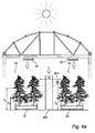
- the sun and top illumination 60 which are typically ceiling mounted HID lamps.
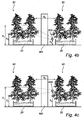
- the general principle of an embodiment of a system for intercanopy lighting in accordance with the present invention is illustrated and in the figures 4a ) to c) possible positions of the lighting device (or luminaire as explained above) in the greenhouse.
- the system typically comprises a plurality of lighting devices or luminaires 600 which are arranged at a position defined by the predetermined height, h 0 , to illuminate a target zone of the plants 50, which are typically arranged in rows of applicable cultivation beds 20.
- one luminaire 600 comprising a plurality of lighting devices, each arranged with one LED of applicable color (typically such to achieve a mixture of blue and red or white and red on the plant surface) is visible.
- the predetermined height h 0 is determined by the direction of the light from the lighting device.
- the luminaire 600 distributes light approximately 28 degrees downwards, which renders the lighting device to be positioned higher than the target zone, which is governed by a lower height limit, h 2 , and a higher height limit, h 1 .
- the angle of the illumination is selected to 28 deg downwards, however the selected angle of the illumination is typically based on the specific kind of plant and the growth stadium of the plant.
- the height of the target zone i.e. h 1 - h 2 , is typically selected within a range of 10 - 50% of the height of a full-grown plant and 100 % for adolescent plants. In the first case the predetermined height is h 0 >h 1 .
- the lighting device is arranged at a horizontal distance d 0 from the target zone, which is chosen such that the luminaire 600 is located outside of the working area WA for the greenhouse staff. Due to the asymmetric shape of the lighting devices in the luminaire 600, the light is efficiently directed to the target zone, starting at height h 1 above ground and ending at height h 2 .
- the target zone of the plant is thus irradiated under a vertical angle which here is approximately 28 degrees downwards.
- Fig. 4b Another example is shown in Fig. 4b ) where the target zone is irradiated under a vertical angle of approximately 45 degrees upwards.
- the vertical angle is greater than or equal to 0 deg. (0 deg means that the direction of the irradiation is parallel to the target zone normal, which is illustrated in Fig. 4c ).
- h 1 is in the order of 1.5 - 2.9 m, while h 2 is approximately 1.0 m.
- the target zone has in the vertical direction a size of 0.5 - 1.0 m.
- a system employing the lighting device which has no reflective substrate and that is positioned as shown in Fig. 4 can reach light target efficiencies of around 70%. As previously described the light target efficiencies may be considerably increased by employing a reflective substrate, which may optionally be shaped.
- Typical separation between the lighting device and the target zone is 0.5 m - 1.5 m (horizontal direction).
- Typical height for mounting of the lighting device is around 2.0 m - however other positions of the lighting devices are applicable for various vertical angles of the irradiation from the lighting devices/luminaires as was explained above.
- the typical target zone corresponds to a beam width in the vertical direction from the lighting device/luminaire of approximately 20 degrees.
Landscapes
- Engineering & Computer Science (AREA)
- General Engineering & Computer Science (AREA)
- Life Sciences & Earth Sciences (AREA)
- Sustainable Development (AREA)
- Sustainable Energy (AREA)
- Environmental Sciences (AREA)
- Non-Portable Lighting Devices Or Systems Thereof (AREA)
- Cultivation Of Plants (AREA)
Claims (15)
- Dispositif optique (100) pour éclairage inter-canopée, comprenant :une zone d'entrée de lumière (109) pour recevoir de la lumière à partir d'une source de lumière ;une première surface (120) possédant une première courbe de Bézier quadratique rationnelle ; etune seconde surface (110) possédant une seconde courbe de Bézier quadratique rationnelle, lesdites première et seconde courbes de Bézier quadratiques rationnelles étant indépendamment sélectionnées l'une par rapport à l'autre, et agencée de sorte que ledit dispositif optique soit rotatif de façon asymétrique par rapport à son axe central,dans lequel de la lumière reçue réfléchie dans ladite première surface est réfléchie dans une direction vers ledit axe central, et dans lequel de la lumière reçue réfléchie dans ladite seconde surface est réfléchie dans une direction s'éloignant dudit axe central, pour ainsi fournir une distribution d'intensité verticale asymétrique sortant du dispositif optique, de sorte que, au niveau d'une zone prédéfinie, ladite zone étant éclairée sous un angle, un éclairage homogène vertical et horizontal soit fourni.
- Dispositif optique selon la revendication 1, dans lequel lesdites première et seconde surfaces réfléchissent de la lumière au moyen de réflexion interne totale, TIR.
- Dispositif optique selon la revendication 1 ou 2, comprenant en outre un élément optique agencé au niveau de ladite zone d'entrée de lumière, dans lequel ledit élément optique est une lentille tronquée de forme conique agencée avec sa base au niveau de ladite zone d'entrée de lumière, dans lequel la troncature de ladite lentille est concave.
- Dispositif optique selon la revendication 1 ou 2, comprenant en outre un élément optique agencé au niveau de ladite zone d'entrée de lumière, dans lequel ledit élément optique est agencé pour rediriger ladite lumière reçue de manière asymétrique, en comprenant une parmi une partie de forme libre asymétrique, une partie de forme cylindrique déplacée, une partie de forme elliptique ou une partie de forme elliptique inclinée.
- Dispositif d'éclairage pour éclairage inter-canopée d'une plante, comprenant :au moins une source de lumière agencée sur un substrat ; etun dispositif optique selon l'une quelconque des revendications précédentes, ledit dispositif optique étant agencé pour recevoir de la lumière à partir de ladite au moins une source de lumière, dans lequel ladite zone prédéterminée est une zone de cible prédéterminée de ladite plante.
- Dispositif d'éclairage selon la revendication 5, dans lequel une hauteur de ladite zone cible prédéterminée pour des plantes adolescentes est sélectionnée pour couvrir 100 % de la hauteur de plante, dans lequel pour des plantes adultes, la hauteur de ladite zone cible prédéterminée est sélectionnées pour couvrir une plage de 10 % à 50 % de la hauteur de plante.
- Dispositif d'éclairage selon la revendication 5 ou 6, dans lequel ledit substrat est agencé pour réfléchir de façon spéculaire.
- Dispositif d'éclairage selon la revendication 7, dans lequel ledit substrat comprend une couche réfléchissante de métal.
- Dispositif d'éclairage selon la revendication 7 ou 8, dans lequel ledit substrat présente une forme d'une parmi plate, parabolique, forme conique, plate combinée avec des parois inclinées plates, plate combinée avec des parois paraboliques, et plate combinée avec des parois de forme de Bézier quadratique rationnelle.
- Dispositif d'éclairage selon l'une quelconque des revendications 5 à 9, dans lequel la source de lumière est une diode électroluminescente.
- Dispositif d'éclairage selon l'une quelconque des revendications 5 à 10, dans lequel une pluralité de sources de lumière sont utilisées dans le dispositif, dans lequel lesdites sources de lumière sont agencées pour émettre une combinaison de lumière rouge et bleue, ou une combinaison de lumière rouge et blanche.
- Système pour éclairage inter-canopée de plantes, ledit système comprenant :une pluralité de dispositifs d'éclairage selon l'une quelconque des revendications 5 à 11 ;des moyens pour agencer lesdits dispositifs d'éclairage à une hauteur prédéterminée h0 et une distance horizontale prédéterminée d0 par rapport à une zone cible prédéterminée desdites plantes ;dans lequel les dispositifs d'éclairage sont agencés pour fournir un motif de faisceau homogène et dirigé pour l'éclairage de ladite zone cible prédéterminée desdites plantes.
- Système selon la revendication 12, dans lequel la hauteur de ladite zone cible prédéterminée est sélectionnée au sein d'une plage de 10 à 50 % de la hauteur de plantes adultes et 100 % de plantes adolescentes.
- Système selon la revendication 12 ou 13, dans lequel ladite distance horizontale d0 est sélectionnée au sein d'une plage de 1,0 à 3,0 m.
- Système selon l'une quelconque des revendications 12 à 14, dans lequel ledit système est agencé de façon mobile de sorte qu'il puisse être levé vers le haut et vers le bas.
Priority Applications (1)
| Application Number | Priority Date | Filing Date | Title |
|---|---|---|---|
| EP11709495.3A EP2542830B1 (fr) | 2010-03-02 | 2011-02-23 | Dispositif optique, système et dispositif d'éclairage pour un éclairage inter-canopée |
Applications Claiming Priority (3)
| Application Number | Priority Date | Filing Date | Title |
|---|---|---|---|
| EP10155114 | 2010-03-02 | ||
| EP11709495.3A EP2542830B1 (fr) | 2010-03-02 | 2011-02-23 | Dispositif optique, système et dispositif d'éclairage pour un éclairage inter-canopée |
| PCT/IB2011/050748 WO2011107901A1 (fr) | 2010-03-02 | 2011-02-23 | Dispositif optique, système et dispositif d'éclairage pour un éclairage inter-canopée |
Publications (2)
| Publication Number | Publication Date |
|---|---|
| EP2542830A1 EP2542830A1 (fr) | 2013-01-09 |
| EP2542830B1 true EP2542830B1 (fr) | 2015-09-30 |
Family
ID=44065155
Family Applications (1)
| Application Number | Title | Priority Date | Filing Date |
|---|---|---|---|
| EP11709495.3A Active EP2542830B1 (fr) | 2010-03-02 | 2011-02-23 | Dispositif optique, système et dispositif d'éclairage pour un éclairage inter-canopée |
Country Status (5)
| Country | Link |
|---|---|
| US (1) | US8939607B2 (fr) |
| EP (1) | EP2542830B1 (fr) |
| CN (1) | CN102792093A (fr) |
| TW (1) | TW201202619A (fr) |
| WO (1) | WO2011107901A1 (fr) |
Families Citing this family (9)
| Publication number | Priority date | Publication date | Assignee | Title |
|---|---|---|---|---|
| ITMI20120488A1 (it) | 2012-03-27 | 2013-09-28 | Fael Spa | Riflettori paraellissoidale e biellissoidale asimmetrici rotazionali per impianti di illuminazione. |
| CN103244870A (zh) * | 2013-04-16 | 2013-08-14 | 广州市明道灯光科技有限公司 | 一种同时包含多种光束效果的舞台灯具系统 |
| TWI491970B (zh) * | 2014-01-03 | 2015-07-11 | Vivotek Inc | 補光結構及應用其補光結構的攝影裝置 |
| DE202015105858U1 (de) * | 2015-11-04 | 2017-02-07 | Zumtobel Lighting Gmbh | Leuchtvorrichtung |
| DE102017001019A1 (de) * | 2017-02-04 | 2018-08-09 | GM Global Technology Operations LLC (n. d. Ges. d. Staates Delaware) | Fahrzeugscheinwerfer |
| WO2019204255A1 (fr) | 2018-04-19 | 2019-10-24 | AGrow-Ray Technologies, Inc. | Visière et luminaire d'extrusion réduisant l'ombre |
| US11337379B2 (en) * | 2019-04-29 | 2022-05-24 | Tammy L. James | Plant growing apparatus |
| CN115179849A (zh) * | 2022-07-20 | 2022-10-14 | 华能秦煤瑞金发电有限责任公司 | 一种车厢遮盖设备及控制方法 |
| CN119817280B (zh) * | 2025-02-28 | 2025-10-10 | 农业农村部南京农业机械化研究所 | 一种基于冠层信息感知的横向变位施肥控制方法 |
Family Cites Families (7)
| Publication number | Priority date | Publication date | Assignee | Title |
|---|---|---|---|---|
| JP4157367B2 (ja) | 2002-11-21 | 2008-10-01 | 住化農業資材株式会社 | 植物の照明装置および照明方法 |
| WO2005083318A1 (fr) * | 2004-02-26 | 2005-09-09 | Tir Systems Ltd. | Appareil pour former un motif de faisceaux lumineux asymetriques |
| DE102004026730A1 (de) | 2004-05-28 | 2005-12-15 | Manfred Kluth | Fläche mit elektrischen Verbrauchern, insbesondere Leuchtmitteln |
| JP2008103300A (ja) * | 2006-09-21 | 2008-05-01 | Toshiba Lighting & Technology Corp | Ledモジュール及び照明器具 |
| CN101784743B (zh) | 2007-08-21 | 2012-09-05 | 皇家飞利浦电子股份有限公司 | 具有被照亮薄片的遮光帘 |
| FI124137B (fi) | 2007-10-26 | 2014-03-31 | Assimilight Oy Ltd | Menetelmä ja järjestely kasvihuonekasvien valaisemiseksi sekä kasvihuoneessa käytettävä vaunu |
| TWI468807B (zh) * | 2012-05-11 | 2015-01-11 | Young Lighting Technology Inc | 背光模組 |
-
2011
- 2011-02-23 US US13/581,585 patent/US8939607B2/en active Active
- 2011-02-23 CN CN2011800119636A patent/CN102792093A/zh active Pending
- 2011-02-23 EP EP11709495.3A patent/EP2542830B1/fr active Active
- 2011-02-23 WO PCT/IB2011/050748 patent/WO2011107901A1/fr not_active Ceased
- 2011-03-01 TW TW100106764A patent/TW201202619A/zh unknown
Non-Patent Citations (1)
| Title |
|---|
| ANONYMOUS: "Bézier curve - Wikipedia, the free encyclopedia", 30 September 2009 (2009-09-30), pages 1 - 6, XP055137128, Retrieved from the Internet <URL:https://web.archive.org/web/20090930115245/http://en.wikipedia.org/wiki/B%C3%A9zier_curve> [retrieved on 20140828] * |
Also Published As
| Publication number | Publication date |
|---|---|
| US20120320570A1 (en) | 2012-12-20 |
| TW201202619A (en) | 2012-01-16 |
| CN102792093A (zh) | 2012-11-21 |
| WO2011107901A1 (fr) | 2011-09-09 |
| US8939607B2 (en) | 2015-01-27 |
| EP2542830A1 (fr) | 2013-01-09 |
| RU2012141895A (ru) | 2014-04-10 |
Similar Documents
| Publication | Publication Date | Title |
|---|---|---|
| EP2542830B1 (fr) | Dispositif optique, système et dispositif d'éclairage pour un éclairage inter-canopée | |
| US11873974B2 (en) | Plant growth lighting systems | |
| EP2567610B1 (fr) | Dispositif d'éclairage à diode électroluminescente (del) pour une serre et serre incorporant un dispositif d'éclairage à diode électroluminescente (del) | |
| US10314243B2 (en) | Horticultural light module assembly | |
| EP2167866B1 (fr) | Luminaire à base de del à forme de faisceau réglable | |
| US11716939B2 (en) | Optical system for facilitating plant growth | |
| US20180292071A1 (en) | Optic assemblies and applications thereof | |
| JP2020510969A (ja) | 導光体を備える照明器具 | |
| US9541255B2 (en) | Luminaires and reflector modules | |
| US20240057528A1 (en) | Optical system for facilitating plant growth having non-uniform light density distribution | |
| US20190120460A1 (en) | Horticultural led illuminator | |
| CN109073206B (zh) | 一种发光装置及手术灯 | |
| JP2001086860A (ja) | 植物栽培用の半導体発光照明設備 | |
| RU2575016C2 (ru) | Оптическое устройство, осветительное устройство и система для освещения межлистового полога растений | |
| JP2005176690A (ja) | 植物育成用照明装置 | |
| CN106641752A (zh) | 一种配光模组及灯具 | |
| JP2015019654A (ja) | 植物栽培装置 |
Legal Events
| Date | Code | Title | Description |
|---|---|---|---|
| PUAI | Public reference made under article 153(3) epc to a published international application that has entered the european phase |
Free format text: ORIGINAL CODE: 0009012 |
|
| 17P | Request for examination filed |
Effective date: 20121002 |
|
| AK | Designated contracting states |
Kind code of ref document: A1 Designated state(s): AL AT BE BG CH CY CZ DE DK EE ES FI FR GB GR HR HU IE IS IT LI LT LU LV MC MK MT NL NO PL PT RO RS SE SI SK SM TR |
|
| DAX | Request for extension of the european patent (deleted) | ||
| RAP1 | Party data changed (applicant data changed or rights of an application transferred) |
Owner name: KONINKLIJKE PHILIPS N.V. |
|
| 17Q | First examination report despatched |
Effective date: 20140903 |
|
| GRAP | Despatch of communication of intention to grant a patent |
Free format text: ORIGINAL CODE: EPIDOSNIGR1 |
|
| INTG | Intention to grant announced |
Effective date: 20150401 |
|
| GRAS | Grant fee paid |
Free format text: ORIGINAL CODE: EPIDOSNIGR3 |
|
| GRAA | (expected) grant |
Free format text: ORIGINAL CODE: 0009210 |
|
| AK | Designated contracting states |
Kind code of ref document: B1 Designated state(s): AL AT BE BG CH CY CZ DE DK EE ES FI FR GB GR HR HU IE IS IT LI LT LU LV MC MK MT NL NO PL PT RO RS SE SI SK SM TR |
|
| REG | Reference to a national code |
Ref country code: CH Ref legal event code: EP Ref country code: GB Ref legal event code: FG4D |
|
| REG | Reference to a national code |
Ref country code: AT Ref legal event code: REF Ref document number: 752636 Country of ref document: AT Kind code of ref document: T Effective date: 20151015 |
|
| REG | Reference to a national code |
Ref country code: IE Ref legal event code: FG4D |
|
| REG | Reference to a national code |
Ref country code: DE Ref legal event code: R096 Ref document number: 602011020463 Country of ref document: DE |
|
| PG25 | Lapsed in a contracting state [announced via postgrant information from national office to epo] |
Ref country code: LV Free format text: LAPSE BECAUSE OF FAILURE TO SUBMIT A TRANSLATION OF THE DESCRIPTION OR TO PAY THE FEE WITHIN THE PRESCRIBED TIME-LIMIT Effective date: 20150930 Ref country code: NO Free format text: LAPSE BECAUSE OF FAILURE TO SUBMIT A TRANSLATION OF THE DESCRIPTION OR TO PAY THE FEE WITHIN THE PRESCRIBED TIME-LIMIT Effective date: 20151230 Ref country code: FI Free format text: LAPSE BECAUSE OF FAILURE TO SUBMIT A TRANSLATION OF THE DESCRIPTION OR TO PAY THE FEE WITHIN THE PRESCRIBED TIME-LIMIT Effective date: 20150930 Ref country code: LT Free format text: LAPSE BECAUSE OF FAILURE TO SUBMIT A TRANSLATION OF THE DESCRIPTION OR TO PAY THE FEE WITHIN THE PRESCRIBED TIME-LIMIT Effective date: 20150930 Ref country code: GR Free format text: LAPSE BECAUSE OF FAILURE TO SUBMIT A TRANSLATION OF THE DESCRIPTION OR TO PAY THE FEE WITHIN THE PRESCRIBED TIME-LIMIT Effective date: 20151231 |
|
| REG | Reference to a national code |
Ref country code: NL Ref legal event code: MP Effective date: 20150930 |
|
| REG | Reference to a national code |
Ref country code: LT Ref legal event code: MG4D |
|
| REG | Reference to a national code |
Ref country code: AT Ref legal event code: MK05 Ref document number: 752636 Country of ref document: AT Kind code of ref document: T Effective date: 20150930 |
|
| PG25 | Lapsed in a contracting state [announced via postgrant information from national office to epo] |
Ref country code: HR Free format text: LAPSE BECAUSE OF FAILURE TO SUBMIT A TRANSLATION OF THE DESCRIPTION OR TO PAY THE FEE WITHIN THE PRESCRIBED TIME-LIMIT Effective date: 20150930 Ref country code: SE Free format text: LAPSE BECAUSE OF FAILURE TO SUBMIT A TRANSLATION OF THE DESCRIPTION OR TO PAY THE FEE WITHIN THE PRESCRIBED TIME-LIMIT Effective date: 20150930 Ref country code: RS Free format text: LAPSE BECAUSE OF FAILURE TO SUBMIT A TRANSLATION OF THE DESCRIPTION OR TO PAY THE FEE WITHIN THE PRESCRIBED TIME-LIMIT Effective date: 20150930 |
|
| REG | Reference to a national code |
Ref country code: FR Ref legal event code: PLFP Year of fee payment: 6 |
|
| PG25 | Lapsed in a contracting state [announced via postgrant information from national office to epo] |
Ref country code: ES Free format text: LAPSE BECAUSE OF FAILURE TO SUBMIT A TRANSLATION OF THE DESCRIPTION OR TO PAY THE FEE WITHIN THE PRESCRIBED TIME-LIMIT Effective date: 20150930 Ref country code: IT Free format text: LAPSE BECAUSE OF FAILURE TO SUBMIT A TRANSLATION OF THE DESCRIPTION OR TO PAY THE FEE WITHIN THE PRESCRIBED TIME-LIMIT Effective date: 20150930 Ref country code: IS Free format text: LAPSE BECAUSE OF FAILURE TO SUBMIT A TRANSLATION OF THE DESCRIPTION OR TO PAY THE FEE WITHIN THE PRESCRIBED TIME-LIMIT Effective date: 20160130 Ref country code: EE Free format text: LAPSE BECAUSE OF FAILURE TO SUBMIT A TRANSLATION OF THE DESCRIPTION OR TO PAY THE FEE WITHIN THE PRESCRIBED TIME-LIMIT Effective date: 20150930 Ref country code: CZ Free format text: LAPSE BECAUSE OF FAILURE TO SUBMIT A TRANSLATION OF THE DESCRIPTION OR TO PAY THE FEE WITHIN THE PRESCRIBED TIME-LIMIT Effective date: 20150930 Ref country code: NL Free format text: LAPSE BECAUSE OF FAILURE TO SUBMIT A TRANSLATION OF THE DESCRIPTION OR TO PAY THE FEE WITHIN THE PRESCRIBED TIME-LIMIT Effective date: 20150930 Ref country code: SK Free format text: LAPSE BECAUSE OF FAILURE TO SUBMIT A TRANSLATION OF THE DESCRIPTION OR TO PAY THE FEE WITHIN THE PRESCRIBED TIME-LIMIT Effective date: 20150930 |
|
| PG25 | Lapsed in a contracting state [announced via postgrant information from national office to epo] |
Ref country code: BE Free format text: LAPSE BECAUSE OF NON-PAYMENT OF DUE FEES Effective date: 20160229 Ref country code: PL Free format text: LAPSE BECAUSE OF FAILURE TO SUBMIT A TRANSLATION OF THE DESCRIPTION OR TO PAY THE FEE WITHIN THE PRESCRIBED TIME-LIMIT Effective date: 20150930 Ref country code: AT Free format text: LAPSE BECAUSE OF FAILURE TO SUBMIT A TRANSLATION OF THE DESCRIPTION OR TO PAY THE FEE WITHIN THE PRESCRIBED TIME-LIMIT Effective date: 20150930 Ref country code: RO Free format text: LAPSE BECAUSE OF FAILURE TO SUBMIT A TRANSLATION OF THE DESCRIPTION OR TO PAY THE FEE WITHIN THE PRESCRIBED TIME-LIMIT Effective date: 20150930 Ref country code: PT Free format text: LAPSE BECAUSE OF FAILURE TO SUBMIT A TRANSLATION OF THE DESCRIPTION OR TO PAY THE FEE WITHIN THE PRESCRIBED TIME-LIMIT Effective date: 20160201 |
|
| REG | Reference to a national code |
Ref country code: DE Ref legal event code: R097 Ref document number: 602011020463 Country of ref document: DE |
|
| PLBE | No opposition filed within time limit |
Free format text: ORIGINAL CODE: 0009261 |
|
| STAA | Information on the status of an ep patent application or granted ep patent |
Free format text: STATUS: NO OPPOSITION FILED WITHIN TIME LIMIT |
|
| PG25 | Lapsed in a contracting state [announced via postgrant information from national office to epo] |
Ref country code: DK Free format text: LAPSE BECAUSE OF FAILURE TO SUBMIT A TRANSLATION OF THE DESCRIPTION OR TO PAY THE FEE WITHIN THE PRESCRIBED TIME-LIMIT Effective date: 20150930 |
|
| 26N | No opposition filed |
Effective date: 20160701 |
|
| PG25 | Lapsed in a contracting state [announced via postgrant information from national office to epo] |
Ref country code: MC Free format text: LAPSE BECAUSE OF FAILURE TO SUBMIT A TRANSLATION OF THE DESCRIPTION OR TO PAY THE FEE WITHIN THE PRESCRIBED TIME-LIMIT Effective date: 20150930 Ref country code: LU Free format text: LAPSE BECAUSE OF FAILURE TO SUBMIT A TRANSLATION OF THE DESCRIPTION OR TO PAY THE FEE WITHIN THE PRESCRIBED TIME-LIMIT Effective date: 20160223 |
|
| REG | Reference to a national code |
Ref country code: CH Ref legal event code: PL |
|
| PG25 | Lapsed in a contracting state [announced via postgrant information from national office to epo] |
Ref country code: CH Free format text: LAPSE BECAUSE OF NON-PAYMENT OF DUE FEES Effective date: 20160229 Ref country code: LI Free format text: LAPSE BECAUSE OF NON-PAYMENT OF DUE FEES Effective date: 20160229 |
|
| REG | Reference to a national code |
Ref country code: GB Ref legal event code: 732E Free format text: REGISTERED BETWEEN 20161006 AND 20161012 |
|
| PG25 | Lapsed in a contracting state [announced via postgrant information from national office to epo] |
Ref country code: SI Free format text: LAPSE BECAUSE OF FAILURE TO SUBMIT A TRANSLATION OF THE DESCRIPTION OR TO PAY THE FEE WITHIN THE PRESCRIBED TIME-LIMIT Effective date: 20150930 |
|
| REG | Reference to a national code |
Ref country code: IE Ref legal event code: MM4A |
|
| PG25 | Lapsed in a contracting state [announced via postgrant information from national office to epo] |
Ref country code: BE Free format text: LAPSE BECAUSE OF FAILURE TO SUBMIT A TRANSLATION OF THE DESCRIPTION OR TO PAY THE FEE WITHIN THE PRESCRIBED TIME-LIMIT Effective date: 20150930 |
|
| PG25 | Lapsed in a contracting state [announced via postgrant information from national office to epo] |
Ref country code: IE Free format text: LAPSE BECAUSE OF NON-PAYMENT OF DUE FEES Effective date: 20160223 |
|
| REG | Reference to a national code |
Ref country code: DE Ref legal event code: R081 Ref document number: 602011020463 Country of ref document: DE Owner name: SIGNIFY HOLDING B.V., NL Free format text: FORMER OWNER: KONINKLIJKE PHILIPS N.V., EINDHOVEN, NL Ref country code: DE Ref legal event code: R082 Ref document number: 602011020463 Country of ref document: DE Representative=s name: MEISSNER BOLTE PATENTANWAELTE RECHTSANWAELTE P, DE Ref country code: DE Ref legal event code: R081 Ref document number: 602011020463 Country of ref document: DE Owner name: PHILIPS LIGHTING HOLDING B.V., NL Free format text: FORMER OWNER: KONINKLIJKE PHILIPS N.V., EINDHOVEN, NL |
|
| REG | Reference to a national code |
Ref country code: FR Ref legal event code: PLFP Year of fee payment: 7 |
|
| PG25 | Lapsed in a contracting state [announced via postgrant information from national office to epo] |
Ref country code: MT Free format text: LAPSE BECAUSE OF FAILURE TO SUBMIT A TRANSLATION OF THE DESCRIPTION OR TO PAY THE FEE WITHIN THE PRESCRIBED TIME-LIMIT Effective date: 20150930 |
|
| REG | Reference to a national code |
Ref country code: FR Ref legal event code: PLFP Year of fee payment: 8 |
|
| PG25 | Lapsed in a contracting state [announced via postgrant information from national office to epo] |
Ref country code: CY Free format text: LAPSE BECAUSE OF FAILURE TO SUBMIT A TRANSLATION OF THE DESCRIPTION OR TO PAY THE FEE WITHIN THE PRESCRIBED TIME-LIMIT Effective date: 20150930 Ref country code: SM Free format text: LAPSE BECAUSE OF FAILURE TO SUBMIT A TRANSLATION OF THE DESCRIPTION OR TO PAY THE FEE WITHIN THE PRESCRIBED TIME-LIMIT Effective date: 20150930 Ref country code: HU Free format text: LAPSE BECAUSE OF FAILURE TO SUBMIT A TRANSLATION OF THE DESCRIPTION OR TO PAY THE FEE WITHIN THE PRESCRIBED TIME-LIMIT; INVALID AB INITIO Effective date: 20110223 |
|
| PG25 | Lapsed in a contracting state [announced via postgrant information from national office to epo] |
Ref country code: MK Free format text: LAPSE BECAUSE OF FAILURE TO SUBMIT A TRANSLATION OF THE DESCRIPTION OR TO PAY THE FEE WITHIN THE PRESCRIBED TIME-LIMIT Effective date: 20150930 Ref country code: MT Free format text: LAPSE BECAUSE OF FAILURE TO SUBMIT A TRANSLATION OF THE DESCRIPTION OR TO PAY THE FEE WITHIN THE PRESCRIBED TIME-LIMIT Effective date: 20160229 Ref country code: TR Free format text: LAPSE BECAUSE OF FAILURE TO SUBMIT A TRANSLATION OF THE DESCRIPTION OR TO PAY THE FEE WITHIN THE PRESCRIBED TIME-LIMIT Effective date: 20150930 |
|
| PG25 | Lapsed in a contracting state [announced via postgrant information from national office to epo] |
Ref country code: BG Free format text: LAPSE BECAUSE OF FAILURE TO SUBMIT A TRANSLATION OF THE DESCRIPTION OR TO PAY THE FEE WITHIN THE PRESCRIBED TIME-LIMIT Effective date: 20150930 |
|
| PG25 | Lapsed in a contracting state [announced via postgrant information from national office to epo] |
Ref country code: AL Free format text: LAPSE BECAUSE OF FAILURE TO SUBMIT A TRANSLATION OF THE DESCRIPTION OR TO PAY THE FEE WITHIN THE PRESCRIBED TIME-LIMIT Effective date: 20150930 |
|
| RIC2 | Information provided on ipc code assigned after grant |
Ipc: F21V 7/00 20060101ALI20110920BHEP Ipc: F21V 5/04 20060101AFI20110920BHEP Ipc: F21Y 101/02 20000101ALI20110920BHEP Ipc: F21V 7/09 20060101ALI20110920BHEP |
|
| REG | Reference to a national code |
Ref country code: DE Ref legal event code: R082 Ref document number: 602011020463 Country of ref document: DE Representative=s name: MEISSNER BOLTE PATENTANWAELTE RECHTSANWAELTE P, DE Ref country code: DE Ref legal event code: R081 Ref document number: 602011020463 Country of ref document: DE Owner name: SIGNIFY HOLDING B.V., NL Free format text: FORMER OWNER: PHILIPS LIGHTING HOLDING B.V., EINDHOVEN, NL |
|
| P01 | Opt-out of the competence of the unified patent court (upc) registered |
Effective date: 20230421 |
|
| PGFP | Annual fee paid to national office [announced via postgrant information from national office to epo] |
Ref country code: FR Payment date: 20250224 Year of fee payment: 15 |
|
| PGFP | Annual fee paid to national office [announced via postgrant information from national office to epo] |
Ref country code: GB Payment date: 20250218 Year of fee payment: 15 |
|
| PGFP | Annual fee paid to national office [announced via postgrant information from national office to epo] |
Ref country code: DE Payment date: 20250428 Year of fee payment: 15 |