EP2543025B1 - Verfahren und vorrichtung zur reduzierung der interferenzwirkung in integrierten systemen zur metallerkennung/überwachung elektronischer artikel - Google Patents
Verfahren und vorrichtung zur reduzierung der interferenzwirkung in integrierten systemen zur metallerkennung/überwachung elektronischer artikel Download PDFInfo
- Publication number
- EP2543025B1 EP2543025B1 EP11767309.5A EP11767309A EP2543025B1 EP 2543025 B1 EP2543025 B1 EP 2543025B1 EP 11767309 A EP11767309 A EP 11767309A EP 2543025 B1 EP2543025 B1 EP 2543025B1
- Authority
- EP
- European Patent Office
- Prior art keywords
- eas
- metal
- metal detection
- frequency
- during
- Prior art date
- Legal status (The legal status is an assumption and is not a legal conclusion. Google has not performed a legal analysis and makes no representation as to the accuracy of the status listed.)
- Active
Links
Images

Classifications
-
- G—PHYSICS
- G08—SIGNALLING
- G08B—SIGNALLING SYSTEMS, e.g. PERSONAL CALLING SYSTEMS; ORDER TELEGRAPHS; ALARM SYSTEMS
- G08B13/00—Burglar, theft or intruder alarms
- G08B13/22—Electrical actuation
- G08B13/24—Electrical actuation by interference with electromagnetic field distribution
- G08B13/2402—Electronic Article Surveillance [EAS], i.e. systems using tags for detecting removal of a tagged item from a secure area, e.g. tags for detecting shoplifting
- G08B13/2465—Aspects related to the EAS system, e.g. system components other than tags
- G08B13/248—EAS system combined with another detection technology, e.g. dual EAS and video or other presence detection system
-
- G—PHYSICS
- G01—MEASURING; TESTING
- G01V—GEOPHYSICS; GRAVITATIONAL MEASUREMENTS; DETECTING MASSES OR OBJECTS; TAGS
- G01V3/00—Electric or magnetic prospecting or detecting; Measuring magnetic field characteristics of the earth, e.g. declination, deviation
- G01V3/08—Electric or magnetic prospecting or detecting; Measuring magnetic field characteristics of the earth, e.g. declination, deviation operating with magnetic or electric fields produced or modified by objects or geological structures or by detecting devices
- G01V3/10—Electric or magnetic prospecting or detecting; Measuring magnetic field characteristics of the earth, e.g. declination, deviation operating with magnetic or electric fields produced or modified by objects or geological structures or by detecting devices using induction coils
-
- G—PHYSICS
- G08—SIGNALLING
- G08B—SIGNALLING SYSTEMS, e.g. PERSONAL CALLING SYSTEMS; ORDER TELEGRAPHS; ALARM SYSTEMS
- G08B13/00—Burglar, theft or intruder alarms
- G08B13/22—Electrical actuation
- G08B13/24—Electrical actuation by interference with electromagnetic field distribution
- G08B13/2402—Electronic Article Surveillance [EAS], i.e. systems using tags for detecting removal of a tagged item from a secure area, e.g. tags for detecting shoplifting
- G08B13/2451—Specific applications combined with EAS
Definitions
- the present invention relates generally electronic article surveillance ("EAS") systems, and more specifically to a method and system for reducing the impact of interference in an integrated EAS/Metal Detection system.
- EAS electronic article surveillance
- EAS systems are commonly used in retail stores and other settings to prevent the unauthorized removal of goods from a protected area.
- a detection system is configured at an exit from the protected area, which comprises one or more transmitters and antennas (“pedestals”) capable of generating an electromagnetic field across the exit, known as the "interrogation zone.”
- Ppedestals transmitters and antennas
- Articles to be protected are tagged with an EAS marker that, when active, generates a response signal when passed through this interrogation zone.
- An antenna and receiver in the same or another "pedestal” detects this response signal and generates an alarm.
- Metal detection systems are also useful in detecting the unauthorized removal of metal items from a protected area. While there exist many metal detection systems, there has been no successful attempt to combine an EAS detection system with a metal detection system. While others have provided a metal detection system adjacent to an EAS system, no one has provided any mechanism for the increased efficiency and cost reduction of actually combining the two systems into one.
- Part of the difficulty in combining both systems into one is the problems that arise due to interference from the transmission signals of other, adjacent EAS transmitters.
- the metal detector is integrated with an acoustomagnetic ("AM") EAS system and both use the same transmitter electronics and tuned antenna coils to transmit both EAS and metal detection signals, an adjacent EAS transmitter will interfere with the metal detection receiver.
- the metal detection frequency is different from the EAS frequency, the sidebands of the adjacent EAS transmitter will have a considerable impact in the metal detection receiver.
- the metal detection frequency cannot vary much from the EAS frequency because the metal detection transmission amplitude will be greatly reduced. This is due to the fact that the systems' antennas are tuned to the EAS transmit frequency.
- WO 2007/101317 A2 discloses a device and process for magnetic material detection in electronic article surveillance electromagnetic systems. The system can only detect magnetic materials and is insensitive to the presence of security tags.
- WO 2010/005499 A2 discloses an EAS system with metal detection capability. For the detection of metal objects in the interrogation zone, metal detection cycles periodically interspersed with at least one EAS detection cycle are used.
- WO 2008/125621 A1 discloses a device for preventing false alarms in a theft-preventing system.
- the system includes a device for detecting metal objects in a detection zone. The detection of the metal objects is based on the detection of changes of the magnetic field in the detection zone.
- US 6,362,739 B1 discloses a passive security device for detecting ferromagnetic objects.
- the device comprises at least one coil.
- the motion of a ferromagnetic object proximate the at least one coil induces a voltage in the coil and is therefore detectable.
- the present invention provides an integrated electronic article surveillance ("EAS”)/metal detection system according to Claim 1
- the present invention provides a metal detection module for an integrated electronic article surveillance (“EAS”)/metal detection system according to Claim 20.
- EAS electronic article surveillance
- relational terms such as “first” and “second,” “top” and “bottom,” and the like, may be used solely to distinguish one entity or element from another entity or element without necessarily requiring or implying any physical or logical relationship or order between such entities or elements.
- One embodiment of the present invention relates to combination EAS/metal detection systems and advantageously provides a method and system for reducing the impact of interference that might arise from adjacent EAS transmitters.
- FIG. 1 one configuration of an exemplary integrated EAS/metal detection system 10 constructed in accordance with the principles of the present invention and located, for example, at a facility entrance.
- EAS detection system 10 includes a pair of pedestals 12a, 12b (collectively referenced as pedestal 12) on opposite sides of an entrance 14.
- pedestal 12 One or more antennas for the EAS detection system 10 may be included in pedestals 12a and 12b, which are located a known distance apart.
- the antennas located in the pedestals 12 are electrically coupled to a control system 16 which controls the operation of the EAS detection system 10.
- an exemplary EAS control system may include a controller 18 (e.g., a processor or microprocessor), a power source 20, a transceiver 22, a memory 24 (which may include non-volatile memory, volatile memory, or a combination thereof), a communication interface 26 and an alarm 28.
- the controller 18 controls radio communications, storage of data to memory 24, communication of stored data to other devices, and activation of the alarm 28.
- the power source 20, such as a battery or AC power supplies electricity to the EAS control system 16.
- the alarm 28 may include software and hardware for providing a visual and/or audible alert in response to detecting an EAS marker and/or metal within an interrogation zone of the EAS system 10.
- the transceiver 22 may include a transmitter 30 electrically coupled to one or more transmitting antennas 32 and a receiver 34 electrically coupled to one or more receiving antennas 36. Alternately, a single antenna or pair of antennas may be used as both the transmitting antenna 32 and the receiving antenna 36.
- the transmitter 30 transmits a radio frequency signal using the transmit antenna 32 to "energize" an EAS marker within the interrogation zone of the EAS system 10.
- the receiver 34 detects the response signal of the EAS marker using the receive antenna 36.
- memory 24 may include a metal detection module 38 for detecting the presence of metal within the interrogation zone.
- Metal detection module 38 may be implemented in hardware and/or software and maybe situated either within memory 24 or outside of memory 24. Operation of the metal detection module 38 is described in greater detail below.
- Metal detection module 38 includes a filter 39 to filter out EAS interrogation signals from nearby EAS systems. Filter 39 can be a notch filter or any other equivalent device, or combination of devices operable to filter out a specific band of frequencies from a given signal.
- metal detection module 38 is shown as a software module stored within memory 24, metal detection module 38 may also be implemented by using discrete components or may be a combination of hardware and software elements.
- metal detection module 38 can, itself, have a controller or other processing unit that performs the filtering and metal detection functions described here.
- filter 39 is described herein as a "notch" filter, the invention is not limited to such. It is contemplated that any filter having a slope sufficient to isolate EAS signal frequencies can be used. For example, a filter with a slope sufficient to filter out a 58kHz EAS interrogation signal when a 56kHz metal detection signal can be used in the present invention.
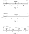
- an EAS detection system may transmit a burst during one time period, then "listen" for a response signal at a subsequent time frame during one detection cycle 40.
- the EAS detection cycle 40 includes four separate time periods: a transmit window 42, a tag detection window 44, a sync window 46 and a noise window 48.
- the exemplary detection cycle 40 is 11.1 msec in duration at a frequency of 90 Hz.
- EM electro -magnetic
- radio frequency signal is transmitted during the transmit window 42 to "energize" an EAS marker having a natural resonant frequency at the same 58kHz frequency.
- the EAS marker has already received and stored an appreciable amount of energy; therefore, the actual EAS marker becomes a source of energy/signal resonating at 58 kHz as its stored energy gradually dissipates (generally known as "ring down”).
- the transmitted EM field may be several orders of magnitude larger than the EAS marker signal.
- the receiver 34 does not operate during transmission. The receiver 34 starts to "listen” for the presence of the EAS marker signal after the transmitter 30 stops transmitting EM energy.
- the EAS marker signal can easily be detected as the background is quiet, i.e. the transmitter 30 is off.
- the receiver 34 also listens again during the sync window 46 and noise window 48, i.e. 3.9 msec and 5.5 msec, respectively, after completion of the transmission of the EM energy burst. By this time, the energy in the EAS marker should be almost completely dissipated, and cannot be detected. However, if a signal still presents, it may indicate the presence of certain unknown interference source(s) and the alarm 28 will be disabled.
- a metal detection cycle 50 includes a metal detection window 52 in place of the transmit window 42.
- the remainder of the metal detection cycle 50 is the same as the original detection cycle 40, i.e. a tag detection window 44, a sync window 46 and a noise window 48.
- One method for detecting metal is based on induced eddy current during an EM excitation.
- the induced eddy current dissipates very quickly, on the order of tens of microseconds in the case of a good conductor. The dissipation is worse with a poor conductor. Even with a good conductor, eddy current dissipation is about two orders of magnitude shorter than that of the acoustic marker.
- the EAS detection system 10 resumes marker detection after the termination of the metal detection transmission cycle 50.
- the same transmitting EM excitation may be used to detect both the presence of metal and the acoustic EAS marker, as shown in FIG. 4 .
- the EAS detection signal is typically transmitted at a frequency of 58 kHz
- the metal detection interrogation signal is typically transmitted at a frequency of 56 kHz.
- FIG. 5 illustrates a hybrid cycle 54, where, in this example, there occurs one metal detection cycle 50 for every three cycles of EAS only detection cycles 40. It should be noted that the sequence and amount of metal detection cycles 50 interspersed per EAS only detection cycles 40 shown in FIG. 5 are for illustrative purposes only. Any combination and/or order of cycles are within the scope of the present invention. Because both the EAS and metal detection systems utilize the same transmitter electronics, the frequency at which metal detection transmission signals are propagated cannot be altered a great deal since the metal detection system is tuned to the EAS transmit frequency. In the embodiment of the present invention illustrated in FIGS. 4 and 5 , the metal detection transmission frequency is set at approximately 56 kHz, which is different from the EAS transmission frequency of 58 kHz.
- the metal detection module includes a notch filter 39 substantially centered at the EAS transmit frequency, in this case 58 kHz. This will "notch" or filter interference that might occur due to adjacent EAS transmitters transmitting at the 58 kHz frequency.
- the notch filter 39 has a bandwidth of approximately 1 kHz- 1.5 kHz, corresponding to 3 dB of attenuation.
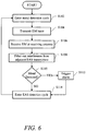
- FIG. 6 is a flowchart that illustrates an exemplary process performed by the metal detection module 38 incorporating the principles of the present invention. This method is based on detecting induced eddy current during an EM excitation.
- One embodiment of the present invention uses only one pedestal for transmitting EM energy while the other pedestal serves as a receiving antenna 36 for metal detection.
- the metal detection module 38 determines a baseline voltage (V r ) developed on the receiving antenna 36 without the presence of metal in the interrogation zone by transmitting a burst of EM energy through the transmit antenna 32 and measuring the voltage induced at the receiving antenna 36.
- V r baseline voltage
- the induced voltage (V r ) developed on the sense coil in the receiving antenna 36 without the presence of metal is quite large due to the transmitting EM field.
- the system 10 enters a metal detection cycle 50 (step S102).
- a burst of EM energy is transmitted through the transmit antenna 32 (step S104) and received at the receiving antenna (step S106).
- the EM energy that is received may contain interference from surrounding EAS transmitters.
- the metal detection module 38 filters out this interference by utilizing a notch filter 39 that is substantially centered at the frequency of surrounding EAS transmitters, e.g., typically, 58 kHz (step S108).
- the received signal strength due to the eddy current effect is significantly smaller than the direct induction voltage induced during the transmitting EM field. It is then determined if metal is present in the interrogation zone (step S110). In one embodiment, if metal is present, the voltage induced is reduced to a value of V m . The net effective received voltage (V s ) due to the presence of metal is calculated as V r - V m , which is a small fraction ( ⁇ a few percent) of the V r . If metal is detected, the metal detection module triggers an alarm (step S112).
- the alarm may be an audible, visual, or tactile alarm, or may notify a security guard or other authorized personnel of the detection of metal being carried through the EAS detection system 10.
- the system 10 then enters the EAS acoustic detection cycle 40 for a predetermined number of iterations (step S114) before repeating the metal detection cycle 50 (step S102).
- the induced eddy current dissipates very quickly, e.g., on the order of tens of microseconds in the case of a good conductor.
- the detection during the metal detection cycle 50 may be reduced compared to that in detection cycle 40 for EAS markers only, where both pedestals may be simultaneous transmitting.
- the same transmitting EM excitation may be used to detect both the presence of metal and the acoustic EAS marker.
- both pedestals may be used for detecting the acoustic EAS markers.
- the present invention provides an integrated EAS/metal detection system 10 that can filter out potentially interfering signals from adjacent EAS transmitters that are transmitting their interrogation signals at the same of substantially the same frequency as the EAS interrogation signals being transmitted by integrated EAS/metal detection system 10.
- a notch filter 39 within the metal detection module 38 that is tuned to the same frequency as adjacent EAS transmitters, extraneous signals may be removed, thus allowing metal detection module 38 to more accurately detect the presence of metal objects within the interrogation zone and not falsely trigger the metal detection alarm when there is no metal object within the interrogation zone.
- the present invention can be realized in hardware, software, or a combination of hardware and software. Any kind of computing system, or other apparatus adapted for carrying out the methods described herein, is suited to perform the functions described herein.
- a typical combination of hardware and software could be a specialized or general purpose computer system having one or more processing elements and a computer program stored on a storage medium that, when loaded and executed, controls the computer system such that it carries out the methods described herein.
- the present invention can also be embedded in a computer program product, which comprises all the features enabling the implementation of the methods described herein, and which, when loaded in a computing system is able to carry out these methods.
- Storage medium refers to any volatile or non-volatile storage device.
- Computer program or application in the present context means any expression, in any language, code or notation, of a set of instructions intended to cause a system having an information processing capability to perform a particular function either directly or after either or both of the following a) conversion to another language, code or notation; b) reproduction in a different material form.
Landscapes
- Physics & Mathematics (AREA)
- Engineering & Computer Science (AREA)
- Electromagnetism (AREA)
- General Physics & Mathematics (AREA)
- Remote Sensing (AREA)
- Life Sciences & Earth Sciences (AREA)
- Automation & Control Theory (AREA)
- Computer Security & Cryptography (AREA)
- Environmental & Geological Engineering (AREA)
- Geology (AREA)
- General Life Sciences & Earth Sciences (AREA)
- Geophysics (AREA)
- Multimedia (AREA)
- Burglar Alarm Systems (AREA)
- Geophysics And Detection Of Objects (AREA)
- Radar Systems Or Details Thereof (AREA)
Claims (20)
- Integriertes System zur Überwachung elektronischer Artikel (EAS)/Metallerkennung (10), umfassend:einen Sender (30), der betrieben werden kann, um ein EAS-Abfragesignal zu senden, wobei das EAS-Abfragesignal einen Abfragebereich etabliert und genutzt wird, um EAS-Markierungen und Metallobjekte innerhalb des Abfragebereichs zu erkennen, wobei das EAS-Abfragesignal während eines EAS-Erkennungszyklus (40) mit einer ersten Frequenz und während eines Metallerkennungszyklus (50) mit einer zweiten Frequenz, die sich von der ersten Frequenz unterscheidet, gesendet wird;einen Empfänger (34), der betrieben werden kann, um ein Signal zu erfassen, das von einer EAS-Markierung empfangen wird; undein Metallerkennungsmodul (38), das betrieben werden kann, um ein Metallobjekt in der Nähe des integrierten EAS-/Metallerkennungssystems (10) zu erkennen, wobei das Metallerkennungsmodul (38) einen Filter (39) umfasst, der im Wesentlichen auf die erste Sendefrequenz ausgemittelt ist, um Signale herauszufiltern, die während der Metallerkennung im Wesentlichen mit der ersten Sendefrequenz empfangen werden.
- System nach Anspruch 1, wobei der Filter (39) ein Kerbfilter ist.
- System nach Anspruch 1, wobei der Filter (39) eine Bandbreite zwischen im Wesentlichen 1 kHz und im Wesentlichen 1,5 kHz aufweist.
- System nach Anspruch 1, wobei das Metallerkennungsmodul (38) betrieben werden kann, um das Metallobjekt in der Nähe des integrierten EAS-/Metallerkennungssystems (10) während des Metallerkennungszyklus (50) basierend auf Perturbationen in dem empfangenen EAS-Markierungssignal zu erkennen, wobei der Metallerkennungszyklus (50) regelmäßig von mindestens einem EAS-Erkennungszyklus (40) unterbrochen wird.
- System nach Anspruch 4, das ferner eine Steuereinheit (16) umfasst, die mit dem Sender (30), dem Empfänger (34) und dem Metallerkennungsmodul (38) elektrisch verbunden ist, wobei die Steuereinheit (16) betrieben werden kann, um das EAS-Markierungssignal während des mindestens einen EAS-Erkennungszyklus (40) zu erkennen.
- System nach Anspruch 1, wobei der Metallerkennungszyklus (50) ein Metallerkennungsfenster (52) umfasst, in dem sowohl der Sender (30) als auch der Empfänger (34) arbeiten.
- System nach Anspruch 4, wobei der mindestens eine EAS-Erkennungszyklus (40) umfasst:ein Sendefenster (42), in dem der Sender (30) arbeitet und der Empfänger (34) nicht arbeitet; undein Empfangsfenster, in dem der Empfänger (34) arbeitet und der Sender (40) nicht arbeitet.
- System nach Anspruch 1, wobei das Metallerkennungsmodul (38) das Metallobjekt erkennt durch:Bestimmen einer ersten Spannung des empfangenen EAS-Markierungssignals, wenn sich das Metallobjekt nicht in der Nähe des integrierten EAS-/Metallerkennungssystems (10) befindet;Vergleichen einer zweiten Spannung des empfangenen EAS-Markierungssignals mit der ersten Spannung; undin Reaktion auf das Bestimmen, dass die zweite Spannung kleiner ist als die erste Spannung, Bestimmen, dass das Metallobjekt vorhanden ist.
- System nach Anspruch 8, wobei die zweite Spannung um mindestens einen vorbestimmten Schwellenwert kleiner ist als die erste Spannung.
- System nach Anspruch 1, das ferner einen Alarm (28) umfasst, wobei in Reaktion auf das Erkennen des in dem Abfragebereich vorhandenen Metallobjekts das Metallerkennungsmodul (38) ferner dazu betrieben werden kann, den Alarm (28) auszulösen.
- System nach Anspruch 1, wobei die erste Frequenz im Wesentlichen 58 kHz und die zweite Frequenz im Wesentlichen 56 kHz beträgt.
- System nach Anspruch 1, wobei der Sender (30) in einem ersten Sockel (12a) und der Empfänger in einem zweiten Sockel (12b) untergebracht ist.
- Verfahren zur Reduzierung der Interferenzwirkung in einem integrierten System zur Überwachung elektronischer Artikel (EAS)/Metallerkennung (10), umfassend:Senden eines EAS-Abfragesignals mithilfe eines Senders (30), wobei das EAS-Abfragesignal einen Abfragebereich etabliert und genutzt wird, um EAS-Markierungen und Metallobjekte innerhalb des Abfragebereichs zu erkennen;wobei das EAS-Abfragesignal während eines EAS-Erkennungszyklus (40) mit einer ersten Frequenz und während eines Metallerkennungszyklus (50) mit einer zweiten Frequenz, die sich von der ersten Frequenz unterscheidet, gesendet wird; Erkennen eines Signals, das von einer EAS-Markierung empfangen wird, mithilfe eines Empfängers (34); undErkennen des Vorhandenseins eines Metallobjekts in der Nähe des integrierten EAS-/Metallerkennungssystems (10) mithilfe eines Metallerkennungsmoduls (38), wobei das Metallerkennungsmodul (38) einen Filter (39) umfasst, der im Wesentlichen auf die erste Sendefrequenz ausgemittelt ist, um Signale herauszufiltern, die während der Metallerkennung im Wesentlichen mit der ersten Sendefrequenz empfangen werden.
- Verfahren nach Anspruch 13, wobei das Herausfiltern von Interferenzsignalen aus angrenzenden EAS-Sendern, die mit der ersten Frequenz senden, mithilfe eines Filters (39) durchgeführt wird, der eine Bandbreite zwischen im Wesentlichen 1 kHz und im Wesentlichen 1,5 kHz aufweist.
- Verfahren nach Anspruch 13, wobei die erste Frequenz im Wesentlichen 58 kHz und die zweite Frequenz im Wesentlichen 56 kHz beträgt.
- Verfahren nach Anspruch 13, das ferner das Erkennen eines Metallobjekts in dem Abfragebereich während eines Metallerkennungszyklus (50) basierend auf Perturbationen in einem empfangenen EAS-Abfragesignal umfasst, wobei der Metallerkennungszyklus (50) regelmäßig von mindestens einem EAS-Erkennungszyklus (40) unterbrochen wird.
- Verfahren nach Anspruch 16, wobei der Metallerkennungszyklus (50) ein Metallerkennungsfenster (52) umfasst, in dem sowohl ein Sender (30) als auch ein Empfänger (34) arbeiten.
- Verfahren nach Anspruch 16, wobei der mindestens eine EAS-Erkennungszyklus (40) umfasst:ein Sendefenster (42), in dem ein Sender (30) arbeitet und ein Empfänger (34) nicht arbeitet; undein Empfangsfenster, in dem der Empfänger (34) arbeitet und der Sender (30) nicht arbeitet.
- Verfahren nach Anspruch 16, wobei das Erkennen des Metallobjekts ferner umfasst:Bestimmen einer ersten Spannung des empfangenen EAS-Markierungssignals, wenn sich das Metallobjekt nicht in der Nähe des EAS-/Metallerkennungssystems (10) befindet;Vergleichen einer zweiten Spannung des empfangenen EAS-Markierungssignals mit der ersten Spannung; undin Reaktion auf das Bestimmen, dass die zweite Spannung kleiner ist als die erste Spannung, Bestimmen, dass das Metallobjekt vorhanden ist.
- Metallerkennungsmodul (38) für ein integriertes System zur Überwachung elektronischer Artikel (EAS)/Metallerkennung (10) nach einem der Ansprüche 1-5, wobei das integrierte EAS-/Metallerkennungssystem (10 während eines EAS-Erkennungszyklus (40) ein EAS-Abfragesignal mit einer ersten Frequenz und während eines Metallerkennungszyklus (50) ein Metallerkennungssignal mit einer zweiten Frequenz, die sich von der ersten Frequenz unterscheidet, sendet,wobei das Metallerkennungsmodul (38) betrieben werden kann, um ein Metallobjekt in der Nähe des EAS-/Metallerkennungssystems (10) zu erkennen;wobei das Metallerkennungsmodul (38) umfasst:einen Filter (39), der im Wesentlichen auf die erste Sendefrequenz ausgemittelt und angeordnet ist, um Signale herauszufiltern, die während der Metallerkennung im Wesentlichen mit der ersten Sendefrequenz empfangen werden; undeine Steuereinheit (16), die betrieben werden kann, um das Vorhandensein von Metallen mithilfe der zweiten Sendefrequenz zu erkennen.
Applications Claiming Priority (2)
| Application Number | Priority Date | Filing Date | Title |
|---|---|---|---|
| US12/716,809 US8659428B2 (en) | 2010-03-03 | 2010-03-03 | Method and system for reducing effect of interference in integrated metal detection/electronic article surveillance systems |
| PCT/US2011/000192 WO2011155966A2 (en) | 2010-03-03 | 2011-02-01 | Method and system for reducing effect of interference in integrated metal detection/electronic article surveillance systems |
Publications (2)
| Publication Number | Publication Date |
|---|---|
| EP2543025A2 EP2543025A2 (de) | 2013-01-09 |
| EP2543025B1 true EP2543025B1 (de) | 2018-05-30 |
Family
ID=44530859
Family Applications (1)
| Application Number | Title | Priority Date | Filing Date |
|---|---|---|---|
| EP11767309.5A Active EP2543025B1 (de) | 2010-03-03 | 2011-02-01 | Verfahren und vorrichtung zur reduzierung der interferenzwirkung in integrierten systemen zur metallerkennung/überwachung elektronischer artikel |
Country Status (8)
| Country | Link |
|---|---|
| US (1) | US8659428B2 (de) |
| EP (1) | EP2543025B1 (de) |
| KR (1) | KR101744898B1 (de) |
| CN (1) | CN102859560B (de) |
| AU (1) | AU2011264686A1 (de) |
| BR (1) | BR112012022201B1 (de) |
| CA (1) | CA2791849C (de) |
| WO (1) | WO2011155966A2 (de) |
Families Citing this family (13)
| Publication number | Priority date | Publication date | Assignee | Title |
|---|---|---|---|---|
| US8816854B2 (en) * | 2009-11-10 | 2014-08-26 | Tyco Fire & Security Gmbh | System and method for reducing cart alarms and increasing sensitivity in an EAS system with metal shielding detection |
| ES2714454T3 (es) * | 2012-01-19 | 2019-05-28 | Sensormatic Electronics Llc | Método y sistema para la cancelación de un patrón de puerta deslizante adaptativa en la detección de metales |
| GB2521398B (en) * | 2013-12-18 | 2020-05-20 | Roke Manor Res Limited | Techniques for co-siting a metal detector with another detector |
| US9589438B1 (en) | 2015-12-03 | 2017-03-07 | Checkpoint Systems, Inc. | Automated optimization of EAS device detection |
| US20170178478A1 (en) * | 2015-12-18 | 2017-06-22 | Checkpoint Systems, Inc. | Reduction of false alarms in eas systems |
| US20180005101A1 (en) * | 2016-06-30 | 2018-01-04 | École De Technologie Supérieure | Method and System for Mitigating Metallic Vibration or Shaking Effects in Proximity of a RFID Reader |
| US20180040218A1 (en) * | 2016-08-04 | 2018-02-08 | Tyco Fire & Security Gmbh | Pulsed electronic article surveillance detection system absent of a phasing requirement |
| US10373454B2 (en) * | 2017-08-15 | 2019-08-06 | Tyco Fire & Security Gmbh | Single-element door/window opening detector |
| CN107748389A (zh) * | 2017-09-30 | 2018-03-02 | 石家庄学院 | 用于检测电缆状态异常的方法及装置 |
| CN110333540A (zh) * | 2019-07-09 | 2019-10-15 | 中科传启(苏州)科技有限公司 | 一种生命体检测方法、设备及行车记录仪 |
| CN110333541A (zh) * | 2019-07-09 | 2019-10-15 | 中科传启(苏州)科技有限公司 | 一种生命体检测方法、设备及行车记录仪 |
| US11704986B2 (en) * | 2020-01-31 | 2023-07-18 | Sensormatic Electronics, LLC | System and method for foil detection using millimeter wave for retail applications |
| EP4016138A1 (de) * | 2020-12-16 | 2022-06-22 | Cassel Meßtechnik GmbH | Vorrichtung zur detektion von metallischen objekten in und an sich gegenüber der vorrichtung bewegenden gegenständen |
Family Cites Families (11)
| Publication number | Priority date | Publication date | Assignee | Title |
|---|---|---|---|---|
| US2337352A (en) * | 1942-08-24 | 1943-12-21 | Gen Electric | Metal detector |
| US4249167A (en) | 1979-06-05 | 1981-02-03 | Magnavox Government And Industrial Electronics Company | Apparatus and method for theft detection system having different frequencies |
| US4622543A (en) * | 1984-03-22 | 1986-11-11 | Anderson Iii Philip M | Surveillance system having acoustic magnetomechanical marker |
| FI95514C (fi) * | 1994-09-26 | 1996-02-12 | Tuotesuoja Sirpa Jaervensivu K | Identifiointimenetelmä sekä identifiointilaitteisto |
| NL1000069C2 (nl) * | 1995-04-07 | 1996-10-08 | Nedap Nv | Anti-diefstalsysteem met geïntegreerde metaaldetector. |
| US6362739B1 (en) * | 1999-09-22 | 2002-03-26 | Garry L. Burton | Passive security device for detecting ferromagnetic objects |
| US6967574B1 (en) * | 2003-01-21 | 2005-11-22 | The Johns Hopkins University | Multi-mode electromagnetic target discriminator sensor system and method of operation thereof |
| US20040199082A1 (en) * | 2003-04-03 | 2004-10-07 | Ostroff Alan H. | Selctable notch filter circuits |
| BRPI0605714B1 (pt) * | 2006-03-07 | 2018-06-26 | José Gouveia Abrunhosa Jorge | Dispositivo e processo para detecção de materiais magnéticos em sistemas antifurtos de tecnologia eletromagnética |
| EP2156419B1 (de) * | 2007-04-13 | 2011-12-28 | Alert Metalguard ApS | Verfahren, einrichtung und system zur verhinderung von falschalarmen in einem diebstahlverhinderungssystem |
| US8704638B2 (en) * | 2008-07-07 | 2014-04-22 | Tyco Fire & Security Services GmbH | Electronic article surveillance system with metal detection capability and method therefor |
-
2010
- 2010-03-03 US US12/716,809 patent/US8659428B2/en active Active
-
2011
- 2011-02-01 EP EP11767309.5A patent/EP2543025B1/de active Active
- 2011-02-01 WO PCT/US2011/000192 patent/WO2011155966A2/en not_active Ceased
- 2011-02-01 KR KR1020127025257A patent/KR101744898B1/ko active Active
- 2011-02-01 BR BR112012022201-5A patent/BR112012022201B1/pt active IP Right Grant
- 2011-02-01 CA CA2791849A patent/CA2791849C/en active Active
- 2011-02-01 AU AU2011264686A patent/AU2011264686A1/en not_active Abandoned
- 2011-02-01 CN CN201180019458.6A patent/CN102859560B/zh active Active
Non-Patent Citations (1)
| Title |
|---|
| None * |
Also Published As
| Publication number | Publication date |
|---|---|
| CA2791849C (en) | 2018-08-28 |
| AU2011264686A1 (en) | 2012-09-20 |
| US8659428B2 (en) | 2014-02-25 |
| KR20130040792A (ko) | 2013-04-24 |
| BR112012022201B1 (pt) | 2019-11-26 |
| CA2791849A1 (en) | 2011-12-15 |
| KR101744898B1 (ko) | 2017-06-08 |
| CN102859560B (zh) | 2016-06-15 |
| EP2543025A2 (de) | 2013-01-09 |
| WO2011155966A2 (en) | 2011-12-15 |
| WO2011155966A3 (en) | 2012-02-16 |
| CN102859560A (zh) | 2013-01-02 |
| US20110215928A1 (en) | 2011-09-08 |
| BR112012022201A2 (pt) | 2016-07-05 |
Similar Documents
| Publication | Publication Date | Title |
|---|---|---|
| CA2791849C (en) | Method and system for reducing effect of interference in integrated metal detection/electronic article surveillance systems | |
| EP2297716B1 (de) | Elektronisches artikelsicherungssystem mit metalldetektionsfähigkeit und verfahren dafür | |
| KR102453223B1 (ko) | 보안 태그 위치들을 결정하기 위한 전자 물품 감시 시스템 구현 방법들 | |
| EP2564244B1 (de) | Verfahren zur minimierung von falschen alarmen bei metalldetektoren | |
| CN107111922B (zh) | 用于区域内检测的系统和方法 | |
| JP2009545784A (ja) | 警報システム、遠隔通信装置、および物品警備方法 | |
| JP2010527485A (ja) | 電子物品監視システムの電力管理のための方法およびシステム | |
| EP2524360B1 (de) | Verfahren und system für empfänger-nulling mit kohärenten übertragungssignalen | |
| JP2009535700A (ja) | 警報システム、ワイヤレス警報装置、および物品警備方法 | |
| US8576045B2 (en) | Synchronization of electronic article surveillance systems having metal detection | |
| EP0736850A1 (de) | Verfahren zum Verhindern von Ladendiebstahl und elektronisches Diebstahl-Detektierungssystem | |
| AU2015252034B2 (en) | Method and system for reducing effect of interference in integrated metal detection/electronic article surveillance systems | |
| JPH0850690A (ja) | 盗難防止システム | |
| HK1176730A (en) | Method and system for reducing effect of interference in integrated metal detection/electronic article surveillance systems | |
| HK1176730B (en) | Method and system for reducing effect of interference in integrated metal detection/electronic article surveillance systems | |
| CN101632104A (zh) | 警报系统、远程通信装置和物品安全保护方法 | |
| HK1239935B (en) | Systems and methods for intra-zone detection | |
| HK1240684B (en) | Electronic article surveillance systems implementing methods for determining security tag locations | |
| HK1239935A1 (en) | Systems and methods for intra-zone detection |
Legal Events
| Date | Code | Title | Description |
|---|---|---|---|
| PUAI | Public reference made under article 153(3) epc to a published international application that has entered the european phase |
Free format text: ORIGINAL CODE: 0009012 |
|
| 17P | Request for examination filed |
Effective date: 20120926 |
|
| AK | Designated contracting states |
Kind code of ref document: A2 Designated state(s): AL AT BE BG CH CY CZ DE DK EE ES FI FR GB GR HR HU IE IS IT LI LT LU LV MC MK MT NL NO PL PT RO RS SE SI SK SM TR |
|
| DAX | Request for extension of the european patent (deleted) | ||
| RAP1 | Party data changed (applicant data changed or rights of an application transferred) |
Owner name: TYCO FIRE & SECURITY GMBH |
|
| STAA | Information on the status of an ep patent application or granted ep patent |
Free format text: STATUS: EXAMINATION IS IN PROGRESS |
|
| 17Q | First examination report despatched |
Effective date: 20170727 |
|
| GRAP | Despatch of communication of intention to grant a patent |
Free format text: ORIGINAL CODE: EPIDOSNIGR1 |
|
| STAA | Information on the status of an ep patent application or granted ep patent |
Free format text: STATUS: GRANT OF PATENT IS INTENDED |
|
| RIC1 | Information provided on ipc code assigned before grant |
Ipc: G08B 13/24 20060101AFI20171221BHEP |
|
| INTG | Intention to grant announced |
Effective date: 20180124 |
|
| RIN1 | Information on inventor provided before grant (corrected) |
Inventor name: BERGMAN, ADAM S. Inventor name: DINH, ERIK LEE Inventor name: SOTO, MANUEL A. |
|
| GRAS | Grant fee paid |
Free format text: ORIGINAL CODE: EPIDOSNIGR3 |
|
| GRAA | (expected) grant |
Free format text: ORIGINAL CODE: 0009210 |
|
| STAA | Information on the status of an ep patent application or granted ep patent |
Free format text: STATUS: THE PATENT HAS BEEN GRANTED |
|
| AK | Designated contracting states |
Kind code of ref document: B1 Designated state(s): AL AT BE BG CH CY CZ DE DK EE ES FI FR GB GR HR HU IE IS IT LI LT LU LV MC MK MT NL NO PL PT RO RS SE SI SK SM TR |
|
| REG | Reference to a national code |
Ref country code: GB Ref legal event code: FG4D |
|
| REG | Reference to a national code |
Ref country code: CH Ref legal event code: EP |
|
| REG | Reference to a national code |
Ref country code: AT Ref legal event code: REF Ref document number: 1004406 Country of ref document: AT Kind code of ref document: T Effective date: 20180615 |
|
| REG | Reference to a national code |
Ref country code: IE Ref legal event code: FG4D |
|
| REG | Reference to a national code |
Ref country code: DE Ref legal event code: R096 Ref document number: 602011048841 Country of ref document: DE |
|
| REG | Reference to a national code |
Ref country code: NL Ref legal event code: MP Effective date: 20180530 |
|
| REG | Reference to a national code |
Ref country code: LT Ref legal event code: MG4D |
|
| PG25 | Lapsed in a contracting state [announced via postgrant information from national office to epo] |
Ref country code: FI Free format text: LAPSE BECAUSE OF FAILURE TO SUBMIT A TRANSLATION OF THE DESCRIPTION OR TO PAY THE FEE WITHIN THE PRESCRIBED TIME-LIMIT Effective date: 20180530 Ref country code: NO Free format text: LAPSE BECAUSE OF FAILURE TO SUBMIT A TRANSLATION OF THE DESCRIPTION OR TO PAY THE FEE WITHIN THE PRESCRIBED TIME-LIMIT Effective date: 20180830 Ref country code: BG Free format text: LAPSE BECAUSE OF FAILURE TO SUBMIT A TRANSLATION OF THE DESCRIPTION OR TO PAY THE FEE WITHIN THE PRESCRIBED TIME-LIMIT Effective date: 20180830 Ref country code: CY Free format text: LAPSE BECAUSE OF FAILURE TO SUBMIT A TRANSLATION OF THE DESCRIPTION OR TO PAY THE FEE WITHIN THE PRESCRIBED TIME-LIMIT Effective date: 20180530 Ref country code: LT Free format text: LAPSE BECAUSE OF FAILURE TO SUBMIT A TRANSLATION OF THE DESCRIPTION OR TO PAY THE FEE WITHIN THE PRESCRIBED TIME-LIMIT Effective date: 20180530 Ref country code: ES Free format text: LAPSE BECAUSE OF FAILURE TO SUBMIT A TRANSLATION OF THE DESCRIPTION OR TO PAY THE FEE WITHIN THE PRESCRIBED TIME-LIMIT Effective date: 20180530 Ref country code: SE Free format text: LAPSE BECAUSE OF FAILURE TO SUBMIT A TRANSLATION OF THE DESCRIPTION OR TO PAY THE FEE WITHIN THE PRESCRIBED TIME-LIMIT Effective date: 20180530 |
|
| PG25 | Lapsed in a contracting state [announced via postgrant information from national office to epo] |
Ref country code: LV Free format text: LAPSE BECAUSE OF FAILURE TO SUBMIT A TRANSLATION OF THE DESCRIPTION OR TO PAY THE FEE WITHIN THE PRESCRIBED TIME-LIMIT Effective date: 20180530 Ref country code: RS Free format text: LAPSE BECAUSE OF FAILURE TO SUBMIT A TRANSLATION OF THE DESCRIPTION OR TO PAY THE FEE WITHIN THE PRESCRIBED TIME-LIMIT Effective date: 20180530 Ref country code: GR Free format text: LAPSE BECAUSE OF FAILURE TO SUBMIT A TRANSLATION OF THE DESCRIPTION OR TO PAY THE FEE WITHIN THE PRESCRIBED TIME-LIMIT Effective date: 20180831 Ref country code: HR Free format text: LAPSE BECAUSE OF FAILURE TO SUBMIT A TRANSLATION OF THE DESCRIPTION OR TO PAY THE FEE WITHIN THE PRESCRIBED TIME-LIMIT Effective date: 20180530 |
|
| REG | Reference to a national code |
Ref country code: AT Ref legal event code: MK05 Ref document number: 1004406 Country of ref document: AT Kind code of ref document: T Effective date: 20180530 |
|
| PG25 | Lapsed in a contracting state [announced via postgrant information from national office to epo] |
Ref country code: NL Free format text: LAPSE BECAUSE OF FAILURE TO SUBMIT A TRANSLATION OF THE DESCRIPTION OR TO PAY THE FEE WITHIN THE PRESCRIBED TIME-LIMIT Effective date: 20180530 |
|
| PG25 | Lapsed in a contracting state [announced via postgrant information from national office to epo] |
Ref country code: PL Free format text: LAPSE BECAUSE OF FAILURE TO SUBMIT A TRANSLATION OF THE DESCRIPTION OR TO PAY THE FEE WITHIN THE PRESCRIBED TIME-LIMIT Effective date: 20180530 Ref country code: EE Free format text: LAPSE BECAUSE OF FAILURE TO SUBMIT A TRANSLATION OF THE DESCRIPTION OR TO PAY THE FEE WITHIN THE PRESCRIBED TIME-LIMIT Effective date: 20180530 Ref country code: AT Free format text: LAPSE BECAUSE OF FAILURE TO SUBMIT A TRANSLATION OF THE DESCRIPTION OR TO PAY THE FEE WITHIN THE PRESCRIBED TIME-LIMIT Effective date: 20180530 Ref country code: DK Free format text: LAPSE BECAUSE OF FAILURE TO SUBMIT A TRANSLATION OF THE DESCRIPTION OR TO PAY THE FEE WITHIN THE PRESCRIBED TIME-LIMIT Effective date: 20180530 Ref country code: SK Free format text: LAPSE BECAUSE OF FAILURE TO SUBMIT A TRANSLATION OF THE DESCRIPTION OR TO PAY THE FEE WITHIN THE PRESCRIBED TIME-LIMIT Effective date: 20180530 Ref country code: CZ Free format text: LAPSE BECAUSE OF FAILURE TO SUBMIT A TRANSLATION OF THE DESCRIPTION OR TO PAY THE FEE WITHIN THE PRESCRIBED TIME-LIMIT Effective date: 20180530 Ref country code: RO Free format text: LAPSE BECAUSE OF FAILURE TO SUBMIT A TRANSLATION OF THE DESCRIPTION OR TO PAY THE FEE WITHIN THE PRESCRIBED TIME-LIMIT Effective date: 20180530 |
|
| PG25 | Lapsed in a contracting state [announced via postgrant information from national office to epo] |
Ref country code: SM Free format text: LAPSE BECAUSE OF FAILURE TO SUBMIT A TRANSLATION OF THE DESCRIPTION OR TO PAY THE FEE WITHIN THE PRESCRIBED TIME-LIMIT Effective date: 20180530 Ref country code: IT Free format text: LAPSE BECAUSE OF FAILURE TO SUBMIT A TRANSLATION OF THE DESCRIPTION OR TO PAY THE FEE WITHIN THE PRESCRIBED TIME-LIMIT Effective date: 20180530 |
|
| REG | Reference to a national code |
Ref country code: DE Ref legal event code: R097 Ref document number: 602011048841 Country of ref document: DE |
|
| PLBE | No opposition filed within time limit |
Free format text: ORIGINAL CODE: 0009261 |
|
| STAA | Information on the status of an ep patent application or granted ep patent |
Free format text: STATUS: NO OPPOSITION FILED WITHIN TIME LIMIT |
|
| 26N | No opposition filed |
Effective date: 20190301 |
|
| REG | Reference to a national code |
Ref country code: DE Ref legal event code: R082 Ref document number: 602011048841 Country of ref document: DE Representative=s name: HAFNER & KOHL PATENTANWALTSKANZLEI RECHTSANWAL, DE Ref country code: DE Ref legal event code: R081 Ref document number: 602011048841 Country of ref document: DE Owner name: SENSORMATIC ELECTRONICS, LLC, BOCA RATON, US Free format text: FORMER OWNER: TYCO FIRE & SECURITY GMBH, NEUHAUSEN AM RHEINFALL, CH Ref country code: DE Ref legal event code: R082 Ref document number: 602011048841 Country of ref document: DE Representative=s name: HAFNER & KOHL PATENT- UND RECHTSANWAELTE PARTN, DE Ref country code: DE Ref legal event code: R082 Ref document number: 602011048841 Country of ref document: DE Representative=s name: HAFNER & KOHL PARTMBB, DE |
|
| PG25 | Lapsed in a contracting state [announced via postgrant information from national office to epo] |
Ref country code: SI Free format text: LAPSE BECAUSE OF FAILURE TO SUBMIT A TRANSLATION OF THE DESCRIPTION OR TO PAY THE FEE WITHIN THE PRESCRIBED TIME-LIMIT Effective date: 20180530 |
|
| REG | Reference to a national code |
Ref country code: CH Ref legal event code: PL |
|
| PG25 | Lapsed in a contracting state [announced via postgrant information from national office to epo] |
Ref country code: LU Free format text: LAPSE BECAUSE OF NON-PAYMENT OF DUE FEES Effective date: 20190201 Ref country code: MC Free format text: LAPSE BECAUSE OF FAILURE TO SUBMIT A TRANSLATION OF THE DESCRIPTION OR TO PAY THE FEE WITHIN THE PRESCRIBED TIME-LIMIT Effective date: 20180530 |
|
| REG | Reference to a national code |
Ref country code: BE Ref legal event code: MM Effective date: 20190228 |
|
| REG | Reference to a national code |
Ref country code: IE Ref legal event code: MM4A |
|
| PG25 | Lapsed in a contracting state [announced via postgrant information from national office to epo] |
Ref country code: AL Free format text: LAPSE BECAUSE OF FAILURE TO SUBMIT A TRANSLATION OF THE DESCRIPTION OR TO PAY THE FEE WITHIN THE PRESCRIBED TIME-LIMIT Effective date: 20180530 |
|
| PG25 | Lapsed in a contracting state [announced via postgrant information from national office to epo] |
Ref country code: CH Free format text: LAPSE BECAUSE OF NON-PAYMENT OF DUE FEES Effective date: 20190228 Ref country code: LI Free format text: LAPSE BECAUSE OF NON-PAYMENT OF DUE FEES Effective date: 20190228 |
|
| REG | Reference to a national code |
Ref country code: GB Ref legal event code: 732E Free format text: REGISTERED BETWEEN 20191205 AND 20191211 |
|
| PG25 | Lapsed in a contracting state [announced via postgrant information from national office to epo] |
Ref country code: IE Free format text: LAPSE BECAUSE OF NON-PAYMENT OF DUE FEES Effective date: 20190201 |
|
| PG25 | Lapsed in a contracting state [announced via postgrant information from national office to epo] |
Ref country code: BE Free format text: LAPSE BECAUSE OF NON-PAYMENT OF DUE FEES Effective date: 20190228 |
|
| PG25 | Lapsed in a contracting state [announced via postgrant information from national office to epo] |
Ref country code: TR Free format text: LAPSE BECAUSE OF FAILURE TO SUBMIT A TRANSLATION OF THE DESCRIPTION OR TO PAY THE FEE WITHIN THE PRESCRIBED TIME-LIMIT Effective date: 20180530 |
|
| PG25 | Lapsed in a contracting state [announced via postgrant information from national office to epo] |
Ref country code: PT Free format text: LAPSE BECAUSE OF FAILURE TO SUBMIT A TRANSLATION OF THE DESCRIPTION OR TO PAY THE FEE WITHIN THE PRESCRIBED TIME-LIMIT Effective date: 20181001 Ref country code: MT Free format text: LAPSE BECAUSE OF NON-PAYMENT OF DUE FEES Effective date: 20190201 |
|
| PG25 | Lapsed in a contracting state [announced via postgrant information from national office to epo] |
Ref country code: IS Free format text: LAPSE BECAUSE OF FAILURE TO SUBMIT A TRANSLATION OF THE DESCRIPTION OR TO PAY THE FEE WITHIN THE PRESCRIBED TIME-LIMIT Effective date: 20180930 |
|
| PG25 | Lapsed in a contracting state [announced via postgrant information from national office to epo] |
Ref country code: HU Free format text: LAPSE BECAUSE OF FAILURE TO SUBMIT A TRANSLATION OF THE DESCRIPTION OR TO PAY THE FEE WITHIN THE PRESCRIBED TIME-LIMIT; INVALID AB INITIO Effective date: 20110201 |
|
| PG25 | Lapsed in a contracting state [announced via postgrant information from national office to epo] |
Ref country code: MK Free format text: LAPSE BECAUSE OF FAILURE TO SUBMIT A TRANSLATION OF THE DESCRIPTION OR TO PAY THE FEE WITHIN THE PRESCRIBED TIME-LIMIT Effective date: 20180530 |
|
| PGFP | Annual fee paid to national office [announced via postgrant information from national office to epo] |
Ref country code: GB Payment date: 20260223 Year of fee payment: 16 |
|
| PGFP | Annual fee paid to national office [announced via postgrant information from national office to epo] |
Ref country code: DE Payment date: 20260220 Year of fee payment: 16 |
|
| PGFP | Annual fee paid to national office [announced via postgrant information from national office to epo] |
Ref country code: FR Payment date: 20260224 Year of fee payment: 16 |