EP2543084B1 - Échangeur de chaleur et procédé de fabrication d'un élément thermoconducteur pour un échangeur de chaleur - Google Patents
Échangeur de chaleur et procédé de fabrication d'un élément thermoconducteur pour un échangeur de chaleur Download PDFInfo
- Publication number
- EP2543084B1 EP2543084B1 EP20110712787 EP11712787A EP2543084B1 EP 2543084 B1 EP2543084 B1 EP 2543084B1 EP 20110712787 EP20110712787 EP 20110712787 EP 11712787 A EP11712787 A EP 11712787A EP 2543084 B1 EP2543084 B1 EP 2543084B1
- Authority
- EP
- European Patent Office
- Prior art keywords
- heat
- temperature controllable
- connecting element
- section
- temperature
- Prior art date
- Legal status (The legal status is an assumption and is not a legal conclusion. Google has not performed a legal analysis and makes no representation as to the accuracy of the status listed.)
- Not-in-force
Links
- 238000004519 manufacturing process Methods 0.000 title claims description 5
- 239000000463 material Substances 0.000 claims description 64
- 238000001816 cooling Methods 0.000 claims description 58
- 229910000679 solder Inorganic materials 0.000 claims description 11
- 239000004020 conductor Substances 0.000 claims description 8
- 238000007599 discharging Methods 0.000 claims description 5
- 238000010438 heat treatment Methods 0.000 claims description 3
- 241000446313 Lamella Species 0.000 description 12
- 239000000498 cooling water Substances 0.000 description 12
- 239000011888 foil Substances 0.000 description 8
- 229910052751 metal Inorganic materials 0.000 description 7
- 239000002184 metal Substances 0.000 description 7
- 239000004065 semiconductor Substances 0.000 description 7
- XLYOFNOQVPJJNP-UHFFFAOYSA-N water Substances O XLYOFNOQVPJJNP-UHFFFAOYSA-N 0.000 description 6
- 239000002826 coolant Substances 0.000 description 5
- 238000005476 soldering Methods 0.000 description 5
- 239000000758 substrate Substances 0.000 description 5
- 229910052797 bismuth Inorganic materials 0.000 description 3
- JCXGWMGPZLAOME-UHFFFAOYSA-N bismuth atom Chemical compound [Bi] JCXGWMGPZLAOME-UHFFFAOYSA-N 0.000 description 3
- 150000002739 metals Chemical class 0.000 description 3
- 238000000034 method Methods 0.000 description 3
- 238000003466 welding Methods 0.000 description 3
- 229910018487 Ni—Cr Inorganic materials 0.000 description 2
- PEEDYJQEMCKDDX-UHFFFAOYSA-N antimony bismuth Chemical compound [Sb].[Bi] PEEDYJQEMCKDDX-UHFFFAOYSA-N 0.000 description 2
- VNNRSPGTAMTISX-UHFFFAOYSA-N chromium nickel Chemical compound [Cr].[Ni] VNNRSPGTAMTISX-UHFFFAOYSA-N 0.000 description 2
- YOCUPQPZWBBYIX-UHFFFAOYSA-N copper nickel Chemical compound [Ni].[Cu] YOCUPQPZWBBYIX-UHFFFAOYSA-N 0.000 description 2
- 230000008878 coupling Effects 0.000 description 2
- 238000010168 coupling process Methods 0.000 description 2
- 238000005859 coupling reaction Methods 0.000 description 2
- 238000009413 insulation Methods 0.000 description 2
- 239000007788 liquid Substances 0.000 description 2
- 229910001092 metal group alloy Inorganic materials 0.000 description 2
- 230000005678 Seebeck effect Effects 0.000 description 1
- 238000010521 absorption reaction Methods 0.000 description 1
- 239000000853 adhesive Substances 0.000 description 1
- 238000004026 adhesive bonding Methods 0.000 description 1
- 230000001070 adhesive effect Effects 0.000 description 1
- 229910052782 aluminium Inorganic materials 0.000 description 1
- XAGFODPZIPBFFR-UHFFFAOYSA-N aluminium Chemical compound [Al] XAGFODPZIPBFFR-UHFFFAOYSA-N 0.000 description 1
- 238000005452 bending Methods 0.000 description 1
- 239000000919 ceramic Substances 0.000 description 1
- 239000011248 coating agent Substances 0.000 description 1
- 238000000576 coating method Methods 0.000 description 1
- 150000001875 compounds Chemical class 0.000 description 1
- 238000010276 construction Methods 0.000 description 1
- 239000000110 cooling liquid Substances 0.000 description 1
- 230000001419 dependent effect Effects 0.000 description 1
- 238000011161 development Methods 0.000 description 1
- 230000018109 developmental process Effects 0.000 description 1
- 230000000694 effects Effects 0.000 description 1
- 238000010292 electrical insulation Methods 0.000 description 1
- 239000012777 electrically insulating material Substances 0.000 description 1
- 239000012799 electrically-conductive coating Substances 0.000 description 1
- 230000017525 heat dissipation Effects 0.000 description 1
- 238000009434 installation Methods 0.000 description 1
- 238000010030 laminating Methods 0.000 description 1
- 238000011084 recovery Methods 0.000 description 1
- GGYFMLJDMAMTAB-UHFFFAOYSA-N selanylidenelead Chemical compound [Pb]=[Se] GGYFMLJDMAMTAB-UHFFFAOYSA-N 0.000 description 1
- 238000000926 separation method Methods 0.000 description 1
- 238000007493 shaping process Methods 0.000 description 1
- 239000007787 solid Substances 0.000 description 1
- XSOKHXFFCGXDJZ-UHFFFAOYSA-N telluride(2-) Chemical compound [Te-2] XSOKHXFFCGXDJZ-UHFFFAOYSA-N 0.000 description 1
- 230000005676 thermoelectric effect Effects 0.000 description 1
Images

Classifications
-
- F—MECHANICAL ENGINEERING; LIGHTING; HEATING; WEAPONS; BLASTING
- F28—HEAT EXCHANGE IN GENERAL
- F28F—DETAILS OF HEAT-EXCHANGE AND HEAT-TRANSFER APPARATUS, OF GENERAL APPLICATION
- F28F1/00—Tubular elements; Assemblies of tubular elements
- F28F1/10—Tubular elements and assemblies thereof with means for increasing heat-transfer area, e.g. with fins, with projections, with recesses
- F28F1/12—Tubular elements and assemblies thereof with means for increasing heat-transfer area, e.g. with fins, with projections, with recesses the means being only outside the tubular element
- F28F1/126—Tubular elements and assemblies thereof with means for increasing heat-transfer area, e.g. with fins, with projections, with recesses the means being only outside the tubular element consisting of zig-zag shaped fins
-
- H—ELECTRICITY
- H10—SEMICONDUCTOR DEVICES; ELECTRIC SOLID-STATE DEVICES NOT OTHERWISE PROVIDED FOR
- H10N—ELECTRIC SOLID-STATE DEVICES NOT OTHERWISE PROVIDED FOR
- H10N10/00—Thermoelectric devices comprising a junction of dissimilar materials, i.e. devices exhibiting Seebeck or Peltier effects
- H10N10/10—Thermoelectric devices comprising a junction of dissimilar materials, i.e. devices exhibiting Seebeck or Peltier effects operating with only the Peltier or Seebeck effects
- H10N10/13—Thermoelectric devices comprising a junction of dissimilar materials, i.e. devices exhibiting Seebeck or Peltier effects operating with only the Peltier or Seebeck effects characterised by the heat-exchanging means at the junction
-
- F—MECHANICAL ENGINEERING; LIGHTING; HEATING; WEAPONS; BLASTING
- F28—HEAT EXCHANGE IN GENERAL
- F28D—HEAT-EXCHANGE APPARATUS, NOT PROVIDED FOR IN ANOTHER SUBCLASS, IN WHICH THE HEAT-EXCHANGE MEDIA DO NOT COME INTO DIRECT CONTACT
- F28D21/00—Heat-exchange apparatus not covered by any of the groups F28D1/00 - F28D20/00
- F28D2021/0019—Other heat exchangers for particular applications; Heat exchange systems not otherwise provided for
- F28D2021/008—Other heat exchangers for particular applications; Heat exchange systems not otherwise provided for for vehicles
- F28D2021/0091—Radiators
- F28D2021/0094—Radiators for recooling the engine coolant
Definitions
- the invention relates to a heat exchanger according to claim 1, a heat exchanger according to claim 14 and a method for producing a heat-conducting element for a heat exchanger according to claim 15.
- Cooling devices which operate in the manner of a heat exchanger and in particular have lines in which a heated cooling medium (eg., A liquid) is guided, the heat energy to be withdrawn.
- a heated cooling medium eg., A liquid
- cooling fins are provided which are in thermal contact with the lines. Heat from the lines and the cooling medium is released via the cooling lamellae to a further medium (in particular air) at a lower temperature, with the additional medium flowing out of the cooling device into the environment after heat absorption, so that heat of the cooling medium is released into the environment unused.
- such cooling devices are used as engine radiator in motor vehicles.
- the problem underlying the invention is to provide a heat exchanger with which the heat energy of a cooling medium can be made as efficient as possible. Furthermore, the invention is based on the problem to provide a method for producing a heat-conducting element for a heat exchanger, which allows the construction of an energy-recovering heat exchanger.
- a thermal generator is realized by the heat conducting element, which generates an electrical voltage under the action of a temperature field generated by the temperature-controlled structures and / or by a heated or cooled medium which is brought into thermal contact with the temperature-controllable structures, i. can be partially converted into electrical energy with the heat energy of the temperature-controlled structures or a medium in contact with these or with the heat-conducting in contact.
- thermoelectric material constituting the first and second connecting members are materials which, when brought into contact with each other, can cause a macroscopically measurable thermoelectric effect (Seebeck effect).
- the first and / or the second thermoelectric material is an electrically conductive material (in particular a metal) or a semiconductor. Concrete examples of the first and second thermoelectric materials will be explained below.
- the heat-conducting element realizes a cooling element, via which heat can be dissipated from the temperature-controllable structures, i. the heat-conducting element has a lower temperature during operation of the heat exchanger than the two temperature-controllable structures.
- a heat sink is formed in the intermediate region between the two heatable structures, i. the intermediate region, which faces the respective second sides of the connecting elements, has a lower temperature than the two temperature-controllable structures.
- the two temperature-controllable structures at least approximately the same temperature, so that sets an approximately symmetrical temperature field with a minimum, which is located approximately in the middle between the two temperature-controllable structures.
- the thermal generator realized by the heat-conducting element of the heat exchanger according to the invention does not have a single hot side, but to a certain extent two hot sides, which are formed by the first sides of the connecting elements facing the first and the second temperature-controllable structure.
- the first sides of the connecting elements are each in thermal contact with the first or second temperature-controllable Structure.
- the cold side of the thermal conduction element thermogenerator is formed by the second sides of the connection elements, which face the lower temperature intermediate region between the temperature-controllable structures and are each in thermal contact with the intermediate region.
- the heat exchanger does not serve to dissipate heat from the temperature-controllable structures, but vice versa to supply heat to the temperature-controllable structures of the heat conducting element.
- the heat-conducting element has a higher temperature during operation of the heat exchanger than the two temperature-controllable elements, so that the respective first sides will have a lower temperature than the respective second sides which face the intermediate space.
- An application of such a heat exchanger is e.g. a dehumidifier.
- first sides of the connecting elements are "connected to one another" via the second section of the heat-conducting element does not necessarily mean that they each have to be directly adjacent to the second section of the heat-conducting element. It is also conceivable that connecting means (eg further metal layers) or other materials are arranged between the first sides and the second section, e.g. serve to minimize the electrical contact resistance between the connecting elements and the associated with them (in electrical contact) areas of the second portion of the heat conducting element.
- a first end region of the second section of the heat-conducting element extends between the first side of the first connecting element and the first temperature-controllable structure.
- a second end region of the second section of the heat-conducting element can extend between the first side of the second connecting element and the second temperature-controllable structure.
- the first and / or the second end region is connected to the first side of the first and the second connecting element, so that over the second portion of the heat-conducting element there is an electrical contact between the first sides of the connecting elements.
- the first sides are in thermal contact with the first and the second temperature-controllable structure via the end regions of the second section.
- first end region of the first portion of the heat-conducting element may be connected to the second side of the first connecting element.
- a can first end portion of the third portion to be connected to the second side of the second connecting element. It is also possible, if the heat-conducting element has further sections connected to one another via additional connecting elements, in each case a second end region of the first or of the third section is connected to a (second) side facing the interspace of a connecting element adjacent to the first or second connecting element such that there is electrical contact between the second sides of adjacent connecting elements.
- the thermal contact between the second sides of the connecting elements and the intermediate region of other (e.g., lower) temperature arises, for example, in that the intermediate region is a substantially air-filled space with which the second sides are each in thermal contact.
- the thermal contact with the intermediate region can also take place via the sections of the heat-conducting element which are connected to the second sides of the connecting elements.
- the heat conducting element passes through the intermediate region of another temperature and can in particular be designed such that via the heat conducting element, i. in particular via the sections of the heat-conducting element connected to the second sides of the connecting elements, heat is removed from the second sides of the connecting elements or heat is supplied to the second sides.
- the heat-conducting element is in particular made of a good heat-conducting material, for. As a metal such as aluminum, formed or has at least one such material.
- the first and / or the second temperature-controllable structure in the form of a conduit for conducting a heated, to be cooled (or a cooled, to be heated) medium is formed.
- the conduit is tubular (such as wood-cylindrical) and in particular formed of a metal or other good heat-conducting material, so that thermal energy of the medium flowing through the conduits to the conduit and e.g. is discharged from this to the heat conducting element.
- a cooling liquid for example, water
- the lines run, for example, at least approximately parallel to one another.
- the temperature-controllable structures can also be configured in other ways be, for example in the form of a (solid) plate, can be transferred to the heat of a medium or absorb heat.
- the plate may be thermally connected to a heat reservoir to receive and dissipate heat therefrom.
- the temperature-controllable structures can have a basically arbitrary shape, which is determined in particular by the intended use of the heat exchanger.
- first and the second temperature-controllable structure can be electrically insulated from the heat-conducting element, in particular in order to avoid a short circuit between the first sides of the connecting elements which face the temperature-controllable structures.
- first and the second temperature-controllable structure can be electrically insulated from the heat-conducting element, in particular in order to avoid a short circuit between the first sides of the connecting elements which face the temperature-controllable structures.
- only those surface sections of the temperature-controllable structures have insulation which come into contact with the cooling lamella (in particular with the first sides of the connecting elements).
- a larger surface area of the temperature-controllable elements e.g. almost its entire the cooling element facing surface area is provided with such insulation.
- the electrical insulation is realized for example by a ceramic, oxide and / or Eloxidbetikung the first and / or the second temperature-controllable structure.
- the first and the second sides of the connecting elements are each opposite one another along a direction perpendicular to the main extension direction of the first and / or the second temperature-controllable structure.
- the "main extension direction” is the longitudinal direction of the line.
- the first and / or the second temperature-controllable structure is not in the form of a line, i. in the form of a hollow body, are formed, but have a massive, yet elongated structure whose longitudinal axis defines the "main direction of extension" of the structure.
- the first connection element is arranged closer to the first temperature-controllable structure than the second connection element
- the second element is arranged closer to the second temperature-controllable structure than the first connection element.
- the connecting elements have an extension in a direction transverse to the main extension direction of the temperature-controllable structures, which is smaller than the distance between the temperature-controllable structures.
- the first side of the connecting elements with one of the temperature-controllable structures is in each case
- thermal contact the second side of the connecting elements does not reach the respective other temperature-controlled structure, but ends in the intermediate space lower temperature between the temperature-controlled structures.
- the connecting elements may have a basically any geometry.
- they are at least approximately spherical in shape, wherein the first and the second sides of a connecting element are formed as portions of a circumference of the ball, which lie opposite each other along a radius of the ball.
- the first and the second "side" of the connecting elements need not necessarily be a flat surface, but e.g. may also be a curved portion of the connecting elements.
- the connecting elements are elongated, z. B. in the form of a cuboid or a cylinder, wherein end faces of the cuboid or the cylinder forming the first and the second sides.
- the first, the second and / or the third section of the heat-conducting element are oriented at least partially at an angle to a direction transverse to the main extension direction of the first and / or the second temperature-controllable structure.
- the first portion extends at a first angle
- the second portion is inclined at a second angle different from the first angle.
- the first and second angles may have at least approximately the same amount but a different "sign", i.
- one section may be inclined in a first direction and another section in the opposite direction with respect to the vertical, resulting in a zigzag-shaped course of the heat-conducting element between the first and the second temperature-controllable structure.
- the heat-conducting element can have, in addition to the three sections, further electrically conductive sections which are connected to one another via additional connecting elements.
- these further sections each extend obliquely to a direction perpendicular to the main extension direction of the first and the second temperature-controllable structure, but they are inclined alternately in a first direction and a second, opposite direction.
- all fasteners i. the additional connecting elements and the first and the second connecting element, arranged so that they - viewed along the main extension of the varnishleitiatas, i. considered in particular along the main extension direction of the temperature-controllable structures - alternately having the first and the second thermoelectric material.
- the first sides of the connecting elements i. those sides of the connecting elements which face the first or the second temperature-controllable structure are in thermal contact alternately with the first and the second temperature-controllable structure.
- a heat conducting element with a chain of a plurality of electrically in series (and thermally parallel) connected connecting elements, wherein the heat conduction through the element into electrical energy convertible heat energy quantity depends in particular on the number of connecting elements.
- the first thermoelectric material has a p-type doping and the second thermoelectric material has an n-type doping, i. the first and the second thermoelectric material are a correspondingly doped semiconductor material, for example a V-VI or IV-VI compound, in particular bismuth telluride or lead selenide.
- the thermoelectric materials have different metals (or other electrically conductive materials) or are formed of different metals.
- the first and / or the second thermoelectric material in the form of a solder material is formed, via which the first portion of the heat-conducting element to the second portion and / or the second portion of the sauceleitelemerits are soldered to the third portion.
- a solder material can, for. B. have as thermoelectric material mentioned bismuth or bismuth antimonide.
- a connecting element comprising soldering material is thus in the form of a soldering spot, e.g. has an at least approximately spherical or elliptical contour.
- the first and / or the second connecting element in the form of a film are formed, for example, has a metal alloy, such as nickel-chromium or nickel-copper.
- the heat-conducting element may comprise both connecting elements in the form of a solder material and connecting elements in the form of a film.
- the heat exchanger according to the invention may also comprise means (eg in the form of a fan) for generating an air flow, which are designed such that the generated air flow hits and / or passes through the heat-conducting element, so that heat is removed from the heat-conducting element by the generated air flow ( or supplied to the heat conducting element).
- the air flow can also contribute to the fact that the second sides of the connecting elements are cooled more efficiently, ie more efficiently heat is removed from the second sides, which constitute the "cold sides" of the connecting elements.
- thermogenerators are used as connecting elements in place of the first and second thermoelectric materials.
- constructive variants of the heat exchanger described in relation to the first aspect can be transferred to the second aspect of the invention.
- thermogenerators which have a plurality of alternately p- and n-doped semiconductor legs.
- the semiconductor legs are electrically connected in series and each form a hot side with a first side and a cold side of the thermal generator with a second side.
- thermogenerators have, for example, a first and a second substrate, which are arranged on their first and second sides, which are formed in particular by the end faces of the semiconductor legs, and on each of which an electrically conductive coating is present, via the two respective ones adjacent sides of the semiconductor legs are electrically connected together.
- microfabricated (miniaturized) thermal generators have a substrate area in the range of 0.5 to 25 mm 2 , with their total height (perpendicular to the substrate including the substrate thickness of such a thermogenerator) being in the range from 100 ⁇ m to 1000 ⁇ m, for example.
- miniaturized thermal generators are known in principle from the prior art, so that they should not be discussed further here.
- thermoelectric material for the connecting elements
- the use of complete thermal generators u.U. the disadvantage that the heat coupling of the heatable structures must be made to the thermoelectrically active semiconductor legs on the substrates and thus may be worse than the coupling to the thermoelectric material.
- connecting elements which are formed from a thermoelectric material, have a higher mechanical stability.
- the invention also relates to a heat exchanger designed as described above, which is designed in the form of an engine radiator of a vehicle.
- the first, second and third sections of the heat-conducting element are provided in that an initially integral section of the heat-conducting element is separated into the first, second and third sections.
- the connecting elements each have a first side (outer side), which are arranged facing away from each other after completion of the heat conducting element and the first or second heatable structure of the heat exchanger are turn.
- the second section of the heat-conducting element is connected to the first and the second side of the connecting element such that a first end region of the second section of the heat-conducting element contacts the first side of the first connecting element and a second end region of the second section of the heat-conducting element contacts the first side of the second connecting element ,
- the inventive method can also be carried out so that the heat-conducting element is separated into more than three sections, between which then each connecting elements are arranged.
- the connecting elements in this case alternately comprise the first and the second thermoelectric material.
- the connecting elements are positioned so that their first sides are alternately facing the first and the second temperature-controllable structure after connecting the heat-conducting element with the first and the second temperature-controllable structure.
- the heat conducting element is a cooling fin, i. in particular around an elongated surface element with a small thickness compared to its length and width, which determine the surface area of the lamella.
- the cooling fin may be approximately zigzag folding, i. several kinks, have.
- the zigzag folded cooling blade is separated at their kinks and "assembled" again via the connecting elements.
- the cooling fin is separated before folding and the subsections generated by the separation connected to each other again via the connecting elements. Subsequently, a folding (or other shaping) of the cooling fin and connecting the cooling fin to the first and the second line.
- thermoelectric material instead of the first and the second thermoelectric material.
- inventive heat exchanger 1 has a first and a second temperature-controlled structure in the form of a respective line 21, 22 for guiding a medium to be cooled in the form of cooling water 5.
- the lines 21, 22 are each connected at a first end to a cooling water inlet 23, flows from the cooling water into the lines 21, 22.
- the cooling water 5 is used to cool an engine (eg a vehicle) and in particular via a pump (not shown) in the lines 21, 22 are pumped.
- Another end of the lines 21, 22 is in each case connected to a drain 24, in which the water 5 flows from the lines 21, 22.
- a heat conducting element in the form of a zigzag between the lines 21, 22 extending back and forth cooling fin 3 is arranged.
- the heated cooling water 5, e.g. at the cooling water inlet 23 has a temperature of 60 to 90 ° C, via the lines 21, 22 and the cooling fin 3 heat to the surrounding the cooling fin 3 air.
- the lines 21, 22 are arranged at a distance from one another such that when flowing through the heated cooling water, a temperature field in the region of the lines 21, 22 builds up, wherein an intermediate region between the lines 21, 22 is formed, which is a lower temperature than the lines 21st , 22, at least when the temperature of the gap with the temperature of the first and second lines 21, 22 at the same position, in the flow direction (in FIG. 1 characterized by arrows A) of the cooling water, is compared.
- the cooling fin 3 has a first electrically conductive portion 31, which is connected via a first connecting element 32 with a second electrically conductive portion 33 of the cooling fin 3.
- the second portion 33 is in turn connected via a second connecting element 34 with a third electrically conductive portion 35 of the cooling fin.
- the cooling plate 3 has further sections 300, which are connected to each other via additional connecting elements 350.
- the first connection element 32 is formed of a first thermoelectric material, the second connection element 34 of a second thermoelectric material.
- the first connection element 32 consists of a first thermoelectric solder material
- the second connection element 34 consists of a second thermoelectric solder material different from the first thermoelectric solder material.
- the first connecting element 32 is made of bismuth
- the second connecting element 34 is formed of bismuth antimonide.
- the first, second and third connecting elements 32, 34, 36 and also the other connecting elements 300 are formed as soldering points and therefore have a substantially spherical or elliptical shape, wherein all connecting elements have substantially the same or at least a similar shape.
- the first and the second connecting element 32, 34 each have a first side 321, 341 which face the first and the second line 21, 22, respectively.
- the first sides 321, 341 are formed by a section of the circumference of the respective connecting element 32, 34, which can also be configured flattened, for example.
- Second sides 322, 342 of the connecting elements 21, 22, which are also each formed by a portion of the circumference of the connecting elements 32, 34, the first sides 321, 341 along a direction perpendicular to the longitudinal direction of the lines 21, 22 opposite to and have accordingly the lines 21, 22 away, so that they are in thermal contact with the gap of lower temperature.
- first sides 321, 341 of the connecting elements when the lines 21, 22 are traversed by the heated cooling water, each represents a "hot side" of the connecting elements, while the second sides 322, 342 of the connecting elements 21, 22, the colder space each facing a "cold side” of the connecting elements 21, 22 form, which has a lower temperature than the hot side.
- the second portion 33 of the cooling fin 3 has a central portion 331, which is inclined relative to the main extension direction of the lines 21, 22, while a first and a second end portion 332, 333 of the second portion 33 substantially parallel to the lines 21, 22 aligned is.
- the parallel end portions 332, 333 extend between the first sides 321, 341 of the connecting members 32, 34 and the first and second leads 21, 22, respectively, with the end portions 332, 333 connected to the first sides, so that electrical contact between the first sides 321, 341 of the connecting elements 32, 34 is realized.
- each of a first surface portion of the end portions 332, 333 contacts the respective first side 321, 341 of the connecting members 32, 34, while a second surface portion of the end portions 332, 333 facing away from the connecting members 32, 34, the outside of the conduit 21, 22nd touched or connected to this, eg by spot welding or cohesively by means of an adhesive or a solder material.
- the second sides 322, 342 of the connecting elements 21, 22 over a portion of the cooling fin 3 each having a second side, that is, a side of a connecting element, which faces away from the gap to the line 21, 22, one other connecting element electrically connected.
- the second side 342 of the second connecting element 34 is connected via the third section 35 of the cooling lamella to a further connecting element 36 arranged adjacently to the second connecting element 34.
- the second side 322 is in contact with an end portion 311 of the first portion 31.
- the cooling fin 3 Due to the electrical connection of the hot and cold sides of adjacent connecting elements over sections of the cooling fin, the cooling fin 3 forms a thermogenerator, which generates an electrical voltage under the action of the temperature field which arises when flowing through the heated cooling water 5 through the lines 21, 22.
- the lines 21, 22 are each provided with an electrically insulating coating or with an electrically insulating material in order to prevent a short circuit between the connecting elements 32, 34, 350.
- the cooling lamella not only has three electrically conductive sections, which are connected to one another via connecting elements, but a multiplicity of further sections 300, which are connected to each other via further connecting elements 350.
- the further connection elements 350 are formed analogously to the first and second connection elements 32, 34 alternately from the first thermoelectric solder material and the second thermoelectric solder material, wherein in each case a first side of the further connection elements with the first and the second line 21, 22 in thermal contact stands.
- all the connecting elements of the cooling fin 3 are electrically connected in series, so that at the ends of the cooling fin thermoelectric voltage U th can be tapped.
- the heat exchanger 1 off FIG. 1 also has means for generating an air flow in the form of a fan 4, which is positioned so that an air flow is formed, which in particular passes through the cooling lamella 3 and dissipates heat from the cooling fin.
- This has in particular the effect that the cold side of realized by the cooling fin 3 Thermegenerators, ie, the second sides 322, 342 of the connecting elements are better cooled.
- the heat exchanger according to the invention has a plurality of cooling fins 3.
- lines 21, 22 further lines between the water inlet 23 and the water outlet 24 may be provided, between each of which further cooling fins, which are formed according to the example of the cooling fin 3 shown, are arranged.
- a heat exchanger according to the invention has 10 to 50 lines leading to cooling water and a corresponding quantity of cooling fins.
- the heat exchanger of the FIG. 1 Although designed to dissipate heat from the first and the second line. However, it is also possible, conversely, for the first and the second line to be supplied with heat via the "cooling lamella", and this heat to be removed via the liquid flowing in the lines. In this way, for example, an air conditioner with energy recovery can be realized.
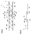
- FIG. 2 shows a further embodiment of the heat exchanger 1 according to the invention, which in principle from the heat exchanger FIG. 1 equivalent.
- a first and a second thermoelectric soldering material instead of a first and a second thermoelectric soldering material, a first and a second film 400, 401 are used for the realization of the connecting elements 32, 34.
- the foils 400, 401 are in particular made of different metals or metal alloys, for example of nickel-chromium or nickel-copper.
- films are used which has a thickness in the range between 50 microns and 200 microns, in particular about 100 microns.
- FIG. 3 One way to produce a cooling fin 3 for the heat exchanger according to the invention is in Fig. 3 illustrated, wherein a section of a cooling fin is shown prior to their installation on the lines of the heat exchanger.
- first separate sections 31, 33, 35 of the cooling fin are provided, for example, characterized in that a first at least partially integral cooling fin is separated.
- the sections 31, 33, 35 are then connected to each other via first and second foils 400, 401 of a first and a second material, wherein the sections 31, 33, 35 are initially aligned substantially parallel to each other.
- the bonding of the foils 400, 401 to the sections 31, 33, 35 takes place for example in such a way that an end region 322 of the first section 31 with a first surface (eg with the entire surface or a partial region) and an end region 322 of the second section 33 with a second surface facing away from the first surface of the first film 400 are connected.
- FIG. 3 only a section of the cooling fin is shown, wherein the entire cooling fin has more than the three sections shown and two connecting foils.
- the bonding of the foils 400, 401 to the sections of the heat-conducting element takes place, for example, via soldering, welding, laminating or gluing.
- the initially substantially rectilinear cooling lamella is brought into the desired shape, for example by repeated bending or folding.
- the cooling lamella is bent in each case in front of or behind the end regions of the cooling lamella sections connected to the foils, so that the cooling lamella, for example, the one in Fig. 2 zig-zag course shown.
- the cooling fin After the cooling fin has been shaped to the desired shape, it is secured to the first and second conduits, in particular by welding some or all of the end portions of the cooling fin portions connected to the sheets to the first and second conduits, respectively.
- FIGS. 1 to 3 can be combined with each other, so z. B. have a part of the connecting elements of a cooling fin connecting elements in the form of a solder material and at the same time other fasteners in the form of a film.
- the connecting elements according to the second aspect of the invention may each be formed by complete thermogenerators instead of a thermoelectric material or a thermoelectric film.
Landscapes
- Physics & Mathematics (AREA)
- Engineering & Computer Science (AREA)
- Geometry (AREA)
- Thermal Sciences (AREA)
- Mechanical Engineering (AREA)
- General Engineering & Computer Science (AREA)
- Air-Conditioning For Vehicles (AREA)
- Heat-Exchange Devices With Radiators And Conduit Assemblies (AREA)
- Devices For Blowing Cold Air, Devices For Blowing Warm Air, And Means For Preventing Water Condensation In Air Conditioning Units (AREA)
Claims (15)
- Echangeur de chaleur comprenant- une première et une deuxième structure thermorégulable (21, 22), lesquelles sont disposées de manière espacée l'une de l'autre de telle manière que lors du réchauffement ou du refroidissement des deux structures thermorégulables (21, 22), une zone intermédiaire se forme entre elles, laquelle présente une température autre que les deux structures thermorégulables (21, 22),- un élément thermoconducteur (3) se trouvant en contact thermique avec la première structure et la deuxième structure thermorégulable (21, 22), servant à évacuer ou à amener de la chaleur de ou vers la première et la deuxième structure thermorégulable (21, 22), sachant que l'élément thermoconducteur (3)- présente une première, une deuxième et une troisième section (31, 33, 35) constituées d'un matériau électroconducteur, caractérisé en ce que- la première section et la deuxième section (31, 33) sont reliées entre elles par l'intermédiaire d'un premier élément d'assemblage (32) constitué d'un premier matériau thermoélectrique, et en ce que la deuxième section et la troisième section (33, 35) sont reliées entre elles par l'intermédiaire d'un deuxième élément d'assemblage (34) constitué d'un deuxième matériau, thermoélectrique, qui est différent du premier matériau thermoélectrique, et sachant- qu'un premier côté (321) du premier élément d'assemblage (32) est tourné vers la première structure thermorégulable (21) et qu'un deuxième côté (322) du premier élément d'assemblage (32) est tourné vers la zone intermédiaire,- qu'un premier côté (341) du deuxième élément d'assemblage (34) est tourné vers la deuxième structure thermorégulable (22) et qu'un deuxième côté (342) du deuxième élément d'assemblage (34) est tourné vers la zone intermédiaire,- que la deuxième section (33) de l'élément thermoconducteur est reliée d'une part au premier côté (321) du premier élément d'assemblage (32) et d'autre part au premier côté (341) du deuxième élément d'assemblage (34),- de sorte que les premiers côtés (321, 341) des éléments d'assemblage (32, 34) sont exposés respectivement à une température autre que ses deuxièmes côtés (322, 342), lorsque la première et la deuxième structure thermorégulable (21, 22) sont réchauffées ou refroidies ensemble et que l'élément thermoconducteur (3) produit une tension électrique à la manière d'un thermogénérateur.
- Echangeur de chaleur selon la revendication 1, caractérisé en ce que la première structure thermorégulable et/ou la deuxième structure thermorégulable sont réalisées sous la forme d'une conduite servant à acheminer un milieu (5) thermorégulable.
- Echangeur de chaleur selon la revendication 2, caractérisé en ce que la première structure thermorégulable et la deuxième structure thermorégulable (21, 22) sont réalisées respectivement sous la forme d'une conduite, et en ce que les conduites s'étendent au moins approximativement de manière parallèle l'une par rapport à l'autre.
- Echangeur de chaleur selon l'une quelconque des revendications précédentes, caractérisé en ce que les premiers côtés et les deuxièmes côtés (321, 341, 322, 342) des éléments d'assemblage (32, 34) se font respectivement face les uns les autres le long d'une direction de manière perpendiculaire par rapport à la direction d'extension principale de la première et/ou de la deuxième structure thermorégulable (21,22).
- Echangeur de chaleur selon l'une quelconque des revendications précédentes, caractérisé en ce qu'une première extrémité (332) de la deuxième section (33) de l'élément thermoconducteur (3) s'étend entre le premier côté (321) du premier élément d'assemblage (32) et la première structure thermorégulable (21), et en ce qu'une deuxième extrémité (333) de la deuxième section (33) de l'élément thermoconducteur (3) s'étend entre le premier côté (341) du deuxième élément d'assemblage (34) et la deuxième structure thermorégulable (22).
- Echangeur de chaleur selon l'une quelconque des revendications précédentes, caractérisé en ce que le premier élément d'assemblage (32) est disposé plus à proximité de la première structure thermorégulable (21) que le deuxième élément d'assemblage (34), et en ce que le deuxième élément d'assemblage (34) est disposé plus à proximité de la deuxième structure thermorégulable (22) que le premier élément d'assemblage (32).
- Echangeur de chaleur selon l'une quelconque des revendications précédentes, caractérisé en ce que la première, la deuxième et/ou la troisième section (31, 33, 35) de l'élément thermoconducteur (3) sont orientées au moins en partie selon un angle par rapport à la direction d'extension principale de la première et/ou de la deuxième structure thermorégulable (21, 22).
- Echangeur de chaleur selon l'une quelconque des revendications précédentes, caractérisé en ce que l'élément thermoconducteur (3) s'étend à la manière d'un zigzag entre la première et la deuxième structure thermorégulable (21, 22).
- Echangeur de chaleur selon l'une quelconque des revendications précédentes, caractérisé en ce que l'élément thermoconducteur présente des éléments d'assemblage (350) supplémentaires, par l'intermédiaire desquels d'autres sections (300) électroconductrices de l'élément thermoconducteur (3) sont reliées les unes aux autres, sachant que tous les éléments d'assemblage (32, 34, 350) présentent le long de l'élément thermoconducteur (3) en alternance le premier et le deuxième matériau thermoélectrique et que les éléments d'assemblage (32, 34, 350) sont en contact thermique par un côté, en alternance avec la première et la deuxième structure thermorégulable (21, 22).
- Echangeur de chaleur selon l'une quelconque des revendications précédentes, caractérisé en ce que le premier matériau thermoélectrique présente un dopage p et le deuxième matériau thermoélectrique présente un dopage n.
- Echangeur de chaleur selon l'une quelconque des revendications précédentes, caractérisé en ce que le premier et/ou le deuxième matériau thermoélectrique est un matériau de brasure, par l'intermédiaire duquel la première section (31) de l'élément thermoconducteur (3) est soudée à la deuxième section (33) de l'élément thermoconducteur (3) et/ou la deuxième section (33) de l'élément thermoconducteur (3) est soudée à la troisième section (35) de l'élément thermoconducteur (3).
- Echangeur de chaleur selon l'une quelconque des revendications précédentes, caractérisé en ce que le premier et/ou le deuxième élément d'assemblage (32, 34) sont réalisés à la manière d'un film (400, 401).
- Echangeur de chaleur selon l'une quelconque des revendications précédentes, caractérisé en ce que la première et la deuxième structure thermorégulable (21, 22) sont isolées électriquement par rapport à l'élément thermoconducteur (3).
- Echangeur de chaleur, comprenant :- une première et une deuxième structure thermorégulable (21, 22), lesquelles sont disposées de manière espacée l'une de l'autre de sorte que lors du réchauffement ou du refroidissement des deux structures thermorégulables (21, 22), un espace intermédiaire se forme entre elles, lequel présente une température autre que les deux structures thermorégulables (21, 22) ;
un élément thermoconducteur (3) se trouvant en contact thermique avec la première et la deuxième structure thermorégulable (21, 22), servant à évacuer ou à amener de la chaleur de ou vers la première et la deuxième structure thermorégulable (21, 22), sachant que l'élément thermoconducteur (3)- présente une première, une deuxième et une troisième section (31, 33, 35) constituées d'un matériau électroconducteur, caractérisé en ce que- la première et la deuxième section (31, 33) sont reliées entre elles par l'intermédiaire d'un premier élément d'assemblage sous la forme d'un premier thermogénérateur, et en ce que la deuxième et la troisième section (33, 35) sont reliées entre elles par l'intermédiaire d'un deuxième élément d'assemblage sous la forme d'un deuxième thermogénérateur, et sachant- qu'un premier côté (321) du premier élément d'assemblage (32) est tourné vers la première structure thermorégulable (21) et qu'un deuxième côté (322) du premier élément d'assemblage (32) est tourné vers la zone intermédiaire,- qu'un premier côté (341) du deuxième élément d'assemblage (34) est tourné vers la deuxième structure thermorégulable (22) et qu'un deuxième côté (342) du deuxième élément d'assemblage (34) est tourné vers la zone intermédiaire,- que la deuxième section (33) de l'élément thermoconducteur (3) est reliée d'une part au premier côté (321) du premier élément d'assemblage (32) et d'autre part au premier côté (341) du deuxième élément d'assemblage (34),- de sorte que les premiers côtés (321, 341) des éléments d'assemblage (32, 34) sont exposés respectivement à une température plus élevée que leurs deuxièmes côtés, lorsque la première et la deuxième structure thermorégulable (21, 22) sont réchauffées ou refroidies par l'intermédiaire du milieu, et que le premier et le deuxième thermogénérateur produisent une tension électrique. - Procédé servant à fabriquer un élément thermoconducteur pour un échangeur de chaleur, en particulier selon l'une quelconque des revendications précédentes, comprenant les étapes suivantes consistant à :- fournir un élément thermoconducteur (3) pouvant être amené en contact thermique avec la première et la deuxième structure thermorégulable (21, 22) de l'échangeur de chaleur, servant à évacuer ou à amener de la chaleur de ou vers la première et la deuxième structure thermorégulable ;- sectionner l'élément thermoconducteur en au moins une première, une deuxième et une troisième section (31, 33, 35) électroconductrice ;- assembler la première section (31) à la deuxième section (33) par l'intermédiaire d'un premier élément d'assemblage (32) constitué d'un premier matériau thermoélectrique ;- assembler la deuxième section (33) à la troisième section (35) par l'intermédiaire d'un deuxième élément d'assemblage (34) constitué d'un deuxième matériau thermoélectrique, qui est différent du premier matériau thermoélectrique.
Applications Claiming Priority (2)
| Application Number | Priority Date | Filing Date | Title |
|---|---|---|---|
| DE102010002623A DE102010002623A1 (de) | 2010-03-05 | 2010-03-05 | Wärmetauscher und Verfahren zum Herstellen eines Wärmeleitelementes für einen Wärmetauscher |
| PCT/EP2011/053104 WO2011107511A2 (fr) | 2010-03-05 | 2011-03-02 | Échangeur de chaleur et procédé de fabrication d'un élément thermoconducteur pour un échangeur de chaleur |
Publications (2)
| Publication Number | Publication Date |
|---|---|
| EP2543084A2 EP2543084A2 (fr) | 2013-01-09 |
| EP2543084B1 true EP2543084B1 (fr) | 2015-04-29 |
Family
ID=44352084
Family Applications (1)
| Application Number | Title | Priority Date | Filing Date |
|---|---|---|---|
| EP20110712787 Not-in-force EP2543084B1 (fr) | 2010-03-05 | 2011-03-02 | Échangeur de chaleur et procédé de fabrication d'un élément thermoconducteur pour un échangeur de chaleur |
Country Status (3)
| Country | Link |
|---|---|
| EP (1) | EP2543084B1 (fr) |
| DE (1) | DE102010002623A1 (fr) |
| WO (1) | WO2011107511A2 (fr) |
Families Citing this family (1)
| Publication number | Priority date | Publication date | Assignee | Title |
|---|---|---|---|---|
| DE102013212817A1 (de) | 2013-07-01 | 2015-01-08 | Schaeffler Technologies Gmbh & Co. Kg | Thermogenerator für Kraftfahrzeuge |
Family Cites Families (14)
| Publication number | Priority date | Publication date | Assignee | Title |
|---|---|---|---|---|
| US2543331A (en) * | 1944-09-01 | 1951-02-27 | Okolicsanyi Ferenc | Thermopile |
| DE1215330B (de) * | 1961-02-25 | 1966-04-28 | Siemens Ag | Vorrichtung zum Kuehlen und Heizen von mit einer Warmfluessigkeitsheizung ausgestatteten Raeumen |
| US3453176A (en) * | 1965-04-13 | 1969-07-01 | Asea Ab | Means for condensing steam liberated within a closed space |
| EP0055175B1 (fr) * | 1980-12-23 | 1984-06-13 | Air Industrie | Installations thermo-électriques |
| DE4129867C2 (de) * | 1991-09-07 | 1995-10-12 | Webasto Ag Fahrzeugtechnik | Thermoelektrischer Generator auf Halbleiterbasis und Verfahren zur Herstellung eines solchen Generators |
| US5837928A (en) * | 1996-09-27 | 1998-11-17 | Zinke; Robert D. | Thermoelectric radiator |
| DE19825561A1 (de) * | 1998-06-08 | 1999-12-09 | Valeo Klimatech Gmbh & Co Kg | Wärmetauscher mit verrippten Flachrohren, insbesondere Heizungswärmetauscher, Motorkühler, Verflüssiger oder Verdampfer, für Kraftfahrzeuge |
| JP4221244B2 (ja) * | 2003-05-14 | 2009-02-12 | カルソニックカンセイ株式会社 | 複合型熱交換器 |
| JP2006177265A (ja) * | 2004-12-22 | 2006-07-06 | Denso Corp | 熱電発電装置 |
| US20060157102A1 (en) * | 2005-01-12 | 2006-07-20 | Showa Denko K.K. | Waste heat recovery system and thermoelectric conversion system |
| DE102007060312B4 (de) * | 2007-08-24 | 2012-12-06 | W.E.T. Automotive Systems Ag | Elektrothermischer Wandler und Temperiereinrichtung |
| DE102008005694B4 (de) * | 2008-01-23 | 2015-05-07 | Fraunhofer-Gesellschaft zur Förderung der angewandten Forschung e.V. | Verfahren zur Herstellung eines thermoelektrischen Bauelementes |
| DE102008039695A1 (de) * | 2008-08-26 | 2010-03-04 | Rammensee, Hans-Georg, Prof. Dr. | Thermoelement, Thermoelementanordnung und feuerfester Formstein mit Thermoelementen sowie ein Stromerzeugungsverfahren mittels Thermoelementen |
| CN201327238Y (zh) * | 2008-10-31 | 2009-10-14 | 上海汽车集团股份有限公司 | 电子水箱散热器 |
-
2010
- 2010-03-05 DE DE102010002623A patent/DE102010002623A1/de not_active Ceased
-
2011
- 2011-03-02 WO PCT/EP2011/053104 patent/WO2011107511A2/fr not_active Ceased
- 2011-03-02 EP EP20110712787 patent/EP2543084B1/fr not_active Not-in-force
Also Published As
| Publication number | Publication date |
|---|---|
| EP2543084A2 (fr) | 2013-01-09 |
| WO2011107511A3 (fr) | 2011-12-22 |
| DE102010002623A1 (de) | 2011-09-22 |
| WO2011107511A2 (fr) | 2011-09-09 |
Similar Documents
| Publication | Publication Date | Title |
|---|---|---|
| EP2513584B1 (fr) | Échangeur thermique thermoélectrique | |
| EP2752084B1 (fr) | Unité de chauffage électrique, dispositif de chauffage pour un véhicule et procédé destiné à fabriquer une unité de chauffage | |
| DE102009013535A1 (de) | Thermoelektrische Vorrichtung | |
| EP2454456A1 (fr) | Dispositif thermoélectrique doté de faisceaux de tubes | |
| EP1515376A2 (fr) | Dispositif pour la génération d'énergie électrique | |
| EP2356704B1 (fr) | Procédé de transformation d'énergie thermique en énergie électrique | |
| EP2376753A1 (fr) | Dispositif permettant la production d'énergie électrique à partir de gaz d'échappement | |
| EP3255688B1 (fr) | Générateur thermoélectrique pour système d'échappement et élément de contact pour un générateur thermoélectrique | |
| EP2230701A2 (fr) | Dispositif thermoélectrique | |
| DE102017222350A1 (de) | Wärmetauscher für eine doppelseitige kühlung von elektronikmodulen | |
| WO2013189970A1 (fr) | Module thermoélectrique, échangeur thermique, système de gaz d'échappement et moteur à combustion interne | |
| EP2552747A1 (fr) | Élément régulateur de température et dispositif régulateur de température pour un véhicule | |
| DE112014006636B4 (de) | Thermoelektrischer Wandler und Verfahren zum Herstellen eines thermoelektrischen Wandlers | |
| EP3323156B1 (fr) | Échangeur de chaleur thermoélectrique | |
| EP2573831B1 (fr) | Tuyau plat segmenté d'une pompe à chaleur thermoélectrique et unité caloporteuse thermoélectrique | |
| WO2011157333A2 (fr) | Conversion électro-thermique | |
| EP2543084B1 (fr) | Échangeur de chaleur et procédé de fabrication d'un élément thermoconducteur pour un échangeur de chaleur | |
| DE102014203139B4 (de) | Verbesserungen betreffend Kontaktbrücken thermoelektrischer Bauelemente, Verwendung eines thermoelektrischen Bauelements, Anlage für Warmwasserbereitung und Thermopaar | |
| EP2939279A1 (fr) | Convertisseur thermoélectrique | |
| DE102010013467A1 (de) | Temperierelement und Temperiervorrichtung für ein Fahrzeug | |
| DE202018102013U1 (de) | Elektrische Heizeinrichtung für mobile Anwendungen | |
| DE202007005127U1 (de) | Halbleiterblockelement und daraus gebildetes Energieerzeugungssystem | |
| WO2010006876A2 (fr) | Dispositif de transfert thermique pour un élément à couche mince thermoélectrique | |
| DE102007024038A1 (de) | Wärmetauscher | |
| DE112016006453B4 (de) | Thermoelektrisches umwandlungsmodul und verfahren zum herstellen desselben |
Legal Events
| Date | Code | Title | Description |
|---|---|---|---|
| PUAI | Public reference made under article 153(3) epc to a published international application that has entered the european phase |
Free format text: ORIGINAL CODE: 0009012 |
|
| 17P | Request for examination filed |
Effective date: 20121005 |
|
| AK | Designated contracting states |
Kind code of ref document: A2 Designated state(s): AL AT BE BG CH CY CZ DE DK EE ES FI FR GB GR HR HU IE IS IT LI LT LU LV MC MK MT NL NO PL PT RO RS SE SI SK SM TR |
|
| DAX | Request for extension of the european patent (deleted) | ||
| RIC1 | Information provided on ipc code assigned before grant |
Ipc: H01L 35/30 20060101AFI20130717BHEP Ipc: F28F 1/12 20060101ALI20130717BHEP Ipc: F28D 21/00 20060101ALI20130717BHEP |
|
| GRAP | Despatch of communication of intention to grant a patent |
Free format text: ORIGINAL CODE: EPIDOSNIGR1 |
|
| INTG | Intention to grant announced |
Effective date: 20131011 |
|
| GRAS | Grant fee paid |
Free format text: ORIGINAL CODE: EPIDOSNIGR3 |
|
| GRAA | (expected) grant |
Free format text: ORIGINAL CODE: 0009210 |
|
| AK | Designated contracting states |
Kind code of ref document: B1 Designated state(s): AL AT BE BG CH CY CZ DE DK EE ES FI FR GB GR HR HU IE IS IT LI LT LU LV MC MK MT NL NO PL PT RO RS SE SI SK SM TR |
|
| REG | Reference to a national code |
Ref country code: GB Ref legal event code: FG4D Free format text: NOT ENGLISH |
|
| REG | Reference to a national code |
Ref country code: AT Ref legal event code: REF Ref document number: 667264 Country of ref document: AT Kind code of ref document: T Effective date: 20140515 |
|
| REG | Reference to a national code |
Ref country code: IE Ref legal event code: FG4D Free format text: LANGUAGE OF EP DOCUMENT: GERMAN |
|
| REG | Reference to a national code |
Ref country code: DE Ref legal event code: R096 Ref document number: 502011003040 Country of ref document: DE Effective date: 20140618 |
|
| REG | Reference to a national code |
Ref country code: NL Ref legal event code: VDEP Effective date: 20140507 |
|
| PUAC | Information related to the publication of a b1 document modified or deleted |
Free format text: ORIGINAL CODE: 0009299EPPU |
|
| REG | Reference to a national code |
Ref country code: LT Ref legal event code: MG4D |
|
| PG25 | Lapsed in a contracting state [announced via postgrant information from national office to epo] |
Ref country code: CY Free format text: LAPSE BECAUSE OF FAILURE TO SUBMIT A TRANSLATION OF THE DESCRIPTION OR TO PAY THE FEE WITHIN THE PRESCRIBED TIME-LIMIT Effective date: 20140507 |
|
| REG | Reference to a national code |
Ref country code: CH Ref legal event code: PK Free format text: DIE ERTEILUNG WURDE VOM EPA WIDERRUFEN. |
|
| 29U | Proceedings interrupted after grant according to rule 142 epc |
Effective date: 20140401 |
|
| DB1 | Publication of patent cancelled |
Effective date: 20141017 |
|
| REG | Reference to a national code |
Ref country code: NL Ref legal event code: GRER Effective date: 20141119 |
|
| 19W | Proceedings resumed before grant after interruption of proceedings |
Effective date: 20150202 |
|
| REG | Reference to a national code |
Ref country code: DE Ref legal event code: R107 Ref document number: 502011003040 Country of ref document: DE Effective date: 20150129 |
|
| RAP1 | Party data changed (applicant data changed or rights of an application transferred) |
Owner name: MICROPATENT B.V. |
|
| GRAA | (expected) grant |
Free format text: ORIGINAL CODE: 0009210 |
|
| AK | Designated contracting states |
Kind code of ref document: B1 Designated state(s): AL AT BE BG CH CY CZ DE DK EE ES FI FR GB GR HR HU IE IS IT LI LT LU LV MC MK MT NL NO PL PT RO RS SE SI SK SM TR |
|
| REG | Reference to a national code |
Ref country code: GB Ref legal event code: FG4D Free format text: NOT ENGLISH |
|
| REG | Reference to a national code |
Ref country code: CH Ref legal event code: EP Ref country code: CH Ref legal event code: PK Free format text: DIE ERTEILUNG VOM 07.05.2014 WURDE VOM EPA WIDERRUFEN |
|
| REG | Reference to a national code |
Ref country code: DE Ref legal event code: R082 Ref document number: 502011003040 Country of ref document: DE Representative=s name: MAIKOWSKI & NINNEMANN PATENTANWAELTE, DE Ref country code: DE Ref legal event code: R082 Ref document number: 502011003040 Country of ref document: DE Representative=s name: MAIKOWSKI & NINNEMANN PATENTANWAELTE PARTNERSC, DE |
|
| REG | Reference to a national code |
Ref country code: GB Ref legal event code: 732E Free format text: REGISTERED BETWEEN 20150514 AND 20150520 |
|
| REG | Reference to a national code |
Ref country code: DE Ref legal event code: R096 Ref document number: 502011003040 Country of ref document: DE Effective date: 20150611 |
|
| REG | Reference to a national code |
Ref country code: AT Ref legal event code: REF Ref document number: 667264 Country of ref document: AT Kind code of ref document: T Effective date: 20150615 |
|
| REG | Reference to a national code |
Ref country code: FR Ref legal event code: PLFP Year of fee payment: 5 |
|
| REG | Reference to a national code |
Ref country code: NL Ref legal event code: VDEP Effective date: 20150429 |
|
| PG25 | Lapsed in a contracting state [announced via postgrant information from national office to epo] |
Ref country code: NL Free format text: LAPSE BECAUSE OF NON-PAYMENT OF DUE FEES Effective date: 20150429 |
|
| PG25 | Lapsed in a contracting state [announced via postgrant information from national office to epo] |
Ref country code: HR Free format text: LAPSE BECAUSE OF FAILURE TO SUBMIT A TRANSLATION OF THE DESCRIPTION OR TO PAY THE FEE WITHIN THE PRESCRIBED TIME-LIMIT Effective date: 20150429 Ref country code: FI Free format text: LAPSE BECAUSE OF NON-PAYMENT OF DUE FEES Effective date: 20150429 Ref country code: NO Free format text: LAPSE BECAUSE OF FAILURE TO SUBMIT A TRANSLATION OF THE DESCRIPTION OR TO PAY THE FEE WITHIN THE PRESCRIBED TIME-LIMIT Effective date: 20150729 |
|
| PG25 | Lapsed in a contracting state [announced via postgrant information from national office to epo] |
Ref country code: PL Free format text: LAPSE BECAUSE OF NON-PAYMENT OF DUE FEES Effective date: 20150429 |
|
| PG25 | Lapsed in a contracting state [announced via postgrant information from national office to epo] |
Ref country code: DK Free format text: LAPSE BECAUSE OF FAILURE TO SUBMIT A TRANSLATION OF THE DESCRIPTION OR TO PAY THE FEE WITHIN THE PRESCRIBED TIME-LIMIT Effective date: 20150429 Ref country code: EE Free format text: LAPSE BECAUSE OF FAILURE TO SUBMIT A TRANSLATION OF THE DESCRIPTION OR TO PAY THE FEE WITHIN THE PRESCRIBED TIME-LIMIT Effective date: 20150429 Ref country code: MC Free format text: LAPSE BECAUSE OF FAILURE TO SUBMIT A TRANSLATION OF THE DESCRIPTION OR TO PAY THE FEE WITHIN THE PRESCRIBED TIME-LIMIT Effective date: 20150429 |
|
| REG | Reference to a national code |
Ref country code: DE Ref legal event code: R097 Ref document number: 502011003040 Country of ref document: DE |
|
| PG25 | Lapsed in a contracting state [announced via postgrant information from national office to epo] |
Ref country code: SK Free format text: LAPSE BECAUSE OF FAILURE TO SUBMIT A TRANSLATION OF THE DESCRIPTION OR TO PAY THE FEE WITHIN THE PRESCRIBED TIME-LIMIT Effective date: 20150429 Ref country code: CZ Free format text: LAPSE BECAUSE OF FAILURE TO SUBMIT A TRANSLATION OF THE DESCRIPTION OR TO PAY THE FEE WITHIN THE PRESCRIBED TIME-LIMIT Effective date: 20150429 |
|
| PLBE | No opposition filed within time limit |
Free format text: ORIGINAL CODE: 0009261 |
|
| STAA | Information on the status of an ep patent application or granted ep patent |
Free format text: STATUS: NO OPPOSITION FILED WITHIN TIME LIMIT |
|
| REG | Reference to a national code |
Ref country code: FR Ref legal event code: PLFP Year of fee payment: 6 |
|
| 26N | No opposition filed |
Effective date: 20160201 |
|
| PG25 | Lapsed in a contracting state [announced via postgrant information from national office to epo] |
Ref country code: SI Free format text: LAPSE BECAUSE OF FAILURE TO SUBMIT A TRANSLATION OF THE DESCRIPTION OR TO PAY THE FEE WITHIN THE PRESCRIBED TIME-LIMIT Effective date: 20150429 |
|
| REG | Reference to a national code |
Ref country code: CH Ref legal event code: PL |
|
| REG | Reference to a national code |
Ref country code: IE Ref legal event code: MM4A |
|
| PG25 | Lapsed in a contracting state [announced via postgrant information from national office to epo] |
Ref country code: LI Free format text: LAPSE BECAUSE OF NON-PAYMENT OF DUE FEES Effective date: 20160331 Ref country code: CH Free format text: LAPSE BECAUSE OF NON-PAYMENT OF DUE FEES Effective date: 20160331 Ref country code: IE Free format text: LAPSE BECAUSE OF NON-PAYMENT OF DUE FEES Effective date: 20160302 |
|
| REG | Reference to a national code |
Ref country code: AT Ref legal event code: MM01 Ref document number: 667264 Country of ref document: AT Kind code of ref document: T Effective date: 20160302 |
|
| PG25 | Lapsed in a contracting state [announced via postgrant information from national office to epo] |
Ref country code: MT Free format text: LAPSE BECAUSE OF FAILURE TO SUBMIT A TRANSLATION OF THE DESCRIPTION OR TO PAY THE FEE WITHIN THE PRESCRIBED TIME-LIMIT Effective date: 20150429 Ref country code: AT Free format text: LAPSE BECAUSE OF NON-PAYMENT OF DUE FEES Effective date: 20160302 |
|
| REG | Reference to a national code |
Ref country code: FR Ref legal event code: PLFP Year of fee payment: 7 |
|
| PGFP | Annual fee paid to national office [announced via postgrant information from national office to epo] |
Ref country code: GB Payment date: 20170925 Year of fee payment: 7 Ref country code: FR Payment date: 20170925 Year of fee payment: 7 |
|
| PG25 | Lapsed in a contracting state [announced via postgrant information from national office to epo] |
Ref country code: LT Free format text: LAPSE BECAUSE OF NON-PAYMENT OF DUE FEES Effective date: 20150429 |
|
| PGFP | Annual fee paid to national office [announced via postgrant information from national office to epo] |
Ref country code: DE Payment date: 20180319 Year of fee payment: 8 |
|
| PG25 | Lapsed in a contracting state [announced via postgrant information from national office to epo] |
Ref country code: SM Free format text: LAPSE BECAUSE OF FAILURE TO SUBMIT A TRANSLATION OF THE DESCRIPTION OR TO PAY THE FEE WITHIN THE PRESCRIBED TIME-LIMIT Effective date: 20150429 Ref country code: RO Free format text: LAPSE BECAUSE OF FAILURE TO SUBMIT A TRANSLATION OF THE DESCRIPTION OR TO PAY THE FEE WITHIN THE PRESCRIBED TIME-LIMIT Effective date: 20150429 Ref country code: LV Free format text: LAPSE BECAUSE OF FAILURE TO SUBMIT A TRANSLATION OF THE DESCRIPTION OR TO PAY THE FEE WITHIN THE PRESCRIBED TIME-LIMIT Effective date: 20150429 Ref country code: HU Free format text: LAPSE BECAUSE OF FAILURE TO SUBMIT A TRANSLATION OF THE DESCRIPTION OR TO PAY THE FEE WITHIN THE PRESCRIBED TIME-LIMIT; INVALID AB INITIO Effective date: 20110302 Ref country code: CY Free format text: LAPSE BECAUSE OF FAILURE TO SUBMIT A TRANSLATION OF THE DESCRIPTION OR TO PAY THE FEE WITHIN THE PRESCRIBED TIME-LIMIT Effective date: 20150429 Ref country code: ES Free format text: LAPSE BECAUSE OF NON-PAYMENT OF DUE FEES Effective date: 20160303 |
|
| PG25 | Lapsed in a contracting state [announced via postgrant information from national office to epo] |
Ref country code: SE Free format text: LAPSE BECAUSE OF NON-PAYMENT OF DUE FEES Effective date: 20150429 Ref country code: BE Free format text: LAPSE BECAUSE OF NON-PAYMENT OF DUE FEES Effective date: 20170331 Ref country code: GR Free format text: LAPSE BECAUSE OF FAILURE TO SUBMIT A TRANSLATION OF THE DESCRIPTION OR TO PAY THE FEE WITHIN THE PRESCRIBED TIME-LIMIT Effective date: 20150429 Ref country code: IT Free format text: LAPSE BECAUSE OF FAILURE TO SUBMIT A TRANSLATION OF THE DESCRIPTION OR TO PAY THE FEE WITHIN THE PRESCRIBED TIME-LIMIT Effective date: 20150429 Ref country code: IS Free format text: LAPSE BECAUSE OF FAILURE TO SUBMIT A TRANSLATION OF THE DESCRIPTION OR TO PAY THE FEE WITHIN THE PRESCRIBED TIME-LIMIT Effective date: 20150429 Ref country code: LU Free format text: LAPSE BECAUSE OF NON-PAYMENT OF DUE FEES Effective date: 20160302 Ref country code: PT Free format text: LAPSE BECAUSE OF FAILURE TO SUBMIT A TRANSLATION OF THE DESCRIPTION OR TO PAY THE FEE WITHIN THE PRESCRIBED TIME-LIMIT Effective date: 20150429 Ref country code: RS Free format text: LAPSE BECAUSE OF FAILURE TO SUBMIT A TRANSLATION OF THE DESCRIPTION OR TO PAY THE FEE WITHIN THE PRESCRIBED TIME-LIMIT Effective date: 20150429 Ref country code: MK Free format text: LAPSE BECAUSE OF FAILURE TO SUBMIT A TRANSLATION OF THE DESCRIPTION OR TO PAY THE FEE WITHIN THE PRESCRIBED TIME-LIMIT Effective date: 20150429 Ref country code: TR Free format text: LAPSE BECAUSE OF FAILURE TO SUBMIT A TRANSLATION OF THE DESCRIPTION OR TO PAY THE FEE WITHIN THE PRESCRIBED TIME-LIMIT Effective date: 20150429 |
|
| PG25 | Lapsed in a contracting state [announced via postgrant information from national office to epo] |
Ref country code: BG Free format text: LAPSE BECAUSE OF FAILURE TO SUBMIT A TRANSLATION OF THE DESCRIPTION OR TO PAY THE FEE WITHIN THE PRESCRIBED TIME-LIMIT Effective date: 20150429 |
|
| PG25 | Lapsed in a contracting state [announced via postgrant information from national office to epo] |
Ref country code: AL Free format text: LAPSE BECAUSE OF FAILURE TO SUBMIT A TRANSLATION OF THE DESCRIPTION OR TO PAY THE FEE WITHIN THE PRESCRIBED TIME-LIMIT Effective date: 20150429 |
|
| GBPC | Gb: european patent ceased through non-payment of renewal fee |
Effective date: 20180302 |
|
| PG25 | Lapsed in a contracting state [announced via postgrant information from national office to epo] |
Ref country code: GB Free format text: LAPSE BECAUSE OF NON-PAYMENT OF DUE FEES Effective date: 20180302 |
|
| PG25 | Lapsed in a contracting state [announced via postgrant information from national office to epo] |
Ref country code: FR Free format text: LAPSE BECAUSE OF NON-PAYMENT OF DUE FEES Effective date: 20180331 |
|
| REG | Reference to a national code |
Ref country code: DE Ref legal event code: R119 Ref document number: 502011003040 Country of ref document: DE |
|
| PG25 | Lapsed in a contracting state [announced via postgrant information from national office to epo] |
Ref country code: DE Free format text: LAPSE BECAUSE OF NON-PAYMENT OF DUE FEES Effective date: 20191001 |