EP2543209B1 - Kommunikationsnetzeinrichtungen und verfahren - Google Patents
Kommunikationsnetzeinrichtungen und verfahren Download PDFInfo
- Publication number
- EP2543209B1 EP2543209B1 EP10707879.2A EP10707879A EP2543209B1 EP 2543209 B1 EP2543209 B1 EP 2543209B1 EP 10707879 A EP10707879 A EP 10707879A EP 2543209 B1 EP2543209 B1 EP 2543209B1
- Authority
- EP
- European Patent Office
- Prior art keywords
- node
- component carrier
- shared
- resources
- coalition
- Prior art date
- Legal status (The legal status is an assumption and is not a legal conclusion. Google has not performed a legal analysis and makes no representation as to the accuracy of the status listed.)
- Active
Links
Images




Classifications
-
- H—ELECTRICITY
- H04—ELECTRIC COMMUNICATION TECHNIQUE
- H04W—WIRELESS COMMUNICATION NETWORKS
- H04W16/00—Network planning, e.g. coverage or traffic planning tools; Network deployment, e.g. resource partitioning or cells structures
- H04W16/02—Resource partitioning among network components, e.g. reuse partitioning
- H04W16/10—Dynamic resource partitioning
Definitions
- Embodiments of the invention relate to communications apparatuses, networks and systems, as well as methods and computer programs for the same.
- a communication system can be seen as a facility that enables communication sessions between two or more entities.
- the communications may comprise, for example, communication of voice, electronic mail (email), text message, multimedia, other data and so on.
- a communication system can be provided, for example, by means of a communication network and one or more compatible communication devices.
- the communication network may be a local network.
- a user can access a communication system by means of an appropriate communication device.
- a communication device of a user is often referred to as user equipment (UE).
- UE user equipment
- a communication device is provided with an appropriate signal receiving and transmitting apparatus for enabling communications with a communication network or communications directly with other users.
- Cellular communication systems are those in which a communications device is able to wirelessly communicate with a network.
- a network entity often called a base station, Node B or evolved Node B (eNB) - collectively access nodes - provide a node for communication with the communication device in one or more cells or sectors.
- Each access node may provide one cell in the area surrounding it.
- an access node may provide a plurality of cells by dividing the area surrounding it into a plurality of sectors.
- the cells in a cellular communication system may overlap. They may be of differing sizes. One large cell may cover a geographic area which additionally contains a plurality of smaller cells.
- This communications network may have connections to further communications networks, including the Internet.
- the bandwidth available for transmissions between a device and an access node generally comprises a plurality of component carriers; and each transmission is made on one or more selected component carriers.
- Component carriers represent a bundle of resources, and may be narrow (i.e. few resources) or wide (many resources).
- Interface coupling is indicative of the degree that the communications of a first access node will interfere with the communications of a second access node. This can be derived from measurements of the signal to interference plus noise ratio (SINR) of communications with a particular access node.
- SINR signal to interference plus noise ratio
- the interference coupling between the first access node and a neighbouring access node describes the effect that the use of the component carrier by the first access node has on the SINR at the neighbouring access node.
- the interference coupling may be sufficiently high (and the SINR sufficiently low) that the particular component carrier is effectively unavailable to the same neighbouring access node.
- the component carriers are allocated between the access nodes in a given area.
- each access node automatically selects one and only one of the component carriers as its primary component carrier (PCC) or base carrier when the access node is powered on.
- the primary component carrier is used for essential functions such as setting up calls between the access node and a communication device; and it has been proposed to assure the quality of the PCC for any access node, and to make the reselection of a new component carrier as the PCC as infrequent as possible.
- Each access node may also autonomously select one or more additional component carriers as secondary component carriers (SCC).
- SCC secondary component carriers
- the main purpose of secondary component carriers is to provide additional capacity whenever possible, and relatively frequent reselection by an access node of different carriers as its secondary component carrier(s) is envisaged.
- the component carriers may therefore be considered shared resources, which are shared between neighbouring access nodes.
- each access node maintains a so-called background interference matrix (BIM), which expresses this interference coupling between neighbouring access nodes.
- BIM background interference matrix
- the BIM is built locally by each access node based on measurements from the communications devices that are served by the access node.
- the BIM describes the interference between neighbouring access nodes.
- ACCS may provide an automatic and fully distributed mechanism for dynamic frequency re-use on a component carrier resolution.
- each component carrier is eligible for use in any cell provided that certain signal to interference plus noise ratio (SINR) constraints are satisfied.
- SINR signal to interference plus noise ratio
- Some cells may be left with nothing but their single primary component carriers since the minimal SINR constraints that all cells use during the SCC selection prevent the use of component carriers for which there is too great an extent of interference coupling.
- the number of secondary component carriers allocated to each cell at any given moment is highly dependent on the time evolution, i.e. the order in which cells have attempted the allocation of extra component carriers, which can result in unfair allocation of resources between the different cells.
- SINR requirements for SCC selection could be set low from the start; nonetheless this approach may entail cells sacrificing the quality (in terms of SINR) of their SCCs for the sake of the network even when it is not necessary.
- EP 2083590 A2 describes an interference mitigation method in a wireless network in which a plurality of nodes share an available frequency spectrum by performing wireless communication on sub-channels defined within the available spectrum.
- US2009/310554 A1 describes a wireless communication network that uses backhaul negotiation based upon static and dynamic resource assignment on jamming graphs.
- the jamming graph is used to summarize the interfering relationship between transmitters (nodes in the jamming graph).
- a negotiation-based algorithm is used to arrive at a static resource assignment so that a large reuse factor can be achieved while jamming scenario can be avoided.
- EP2073587 A2 describes a spectrum-assignment method for use in a wireless communication system, which, on a dynamic basis, controls re-assignments of the spectrum between communication apparatuses of the system.
- the invention consists of methods and apparatuses as defined in independent claims 1, 10, 11, 20, 21 and 22. Embodiments of the invention are defined in the dependent claims.
- a method comprising: determining that additional shared component carrier resources are required by a first node, the shared component carrier resources being shared with one or more second nodes; determining the identity of at least one of the one of more second nodes with which the first node has a strong interference bond for the shared component carrier resources; sending a request to the at least one second node for information relating to the use of the shared component carrier resources; receiving a response from the at least one second node, the response comprising information relating to the use of the shared component carrier resources; determining, in the first node, the amount of shared component carrier resources allocated; and causing at least one allocation message to be sent to the at least one second node, the allocation message indicating that at least a part of the shared component carrier resources used by the at least one second node has been allocated to the first node.
- the first node forms a coalition with the at least one second node based on information sent in the at least one allocation message.
- the response comprises at least one of: information relating to what shared component carrier resources are being used by the at least one second node; information relating to what shared component carrier resources, used by the at least one second node, may be allocated to the first node; information relating to whether the at least one second node forms a coalition with one or more further nodes.
- the method further comprises: determining based on the response, whether there are free shared component carrier resources which are free to be used by the first node; wherein, if there are free resources, the at least one allocation message comprises information identifying the free shared component carrier resources.
- the method further comprises: receiving information defining interference bonding between the first node and the at least one second node; storing the received information in a memory, wherein the determining the identity of at least one second node comprises reading information from the memory.
- the received information is received from a communication device with which the first node is able to communicate using the shared component carrier resources.
- an interference bond represents the amount which the signalling associated with the shared component carrier resource and the at least one second access node affects the signalling associated with the shared resource and the first node.
- a strong interference bond is indicative that the interference bond renders simultaneous use of the shared component carrier resource by the first and the at least one second node less efficient than coordinated use of the shared component carrier resource.
- the shared component carrier resources comprise portions of component carriers.
- the portions of component carriers are orthogonal within the time domain.
- the at least one second node comprises two second nodes and wherein the first node is allocated a first part of the shared component carrier resources, one second node is allocated a second part of the shared component carrier resources, and a further second node is allocated a third part of the shared component carrier resources.
- a computer program product embodied on a computer readable medium which contains computer readable instructions which when performed on one or more processors perform the method as described above.
- an apparatus comprising: determining means for determining that additional shared component carrier resources are required by a first node, the shared component carrier resources being shared with one or more second nodes; and for determining the identity of at least one of the one of more second nodes with which the first node has a strong interference bond for the shared component carrier resources; and means for causing at least one allocation message to be sent to the at least one second node, the allocation message indicating that at least a part of the shared component carrier resources used by the at least one second node has been allocated to the first node.
- the first node is configured to form a coalition with the at least one second node based on information sent in the at least one allocation message.
- the response comprises at least one of: information relating to what shared component carrier resources are being used by the at least one second node; information relating to what shared resources, used by the at least one second node, may be allocated to the first node; information relating to whether the at least one second node forms a coalition with one or more further nodes.
- Optionally determining means is configured to determine, based on the response, whether there are free shared component carrier resources which are free to be used by the first node; and wherein, if there are free resources, the at least one allocation message comprises information identifying the free shared component carrier resources.
- the apparatus further comprises: means for receiving information defining interference bonding between the first node and the at least one second node; a memory for storing the received information, wherein the determining means comprises means for reading the information from the memory.
- the means for receiving information defining interference bonding between the first node and the at least one second node is configured to receive information from a communication device with which the first node is able to communicate using the shared resources.
- an interference bond represents the amount which the signalling associated with the shared component carrier resource and the at least one second access node affects the signalling associated with the shared component carrier resource and the first node.
- a strong interference bond is indicative that the interference bond renders simultaneous use of the shared component carrier resource by the first and the at least one second node less efficient than coordinated use of the shared component carrier resource.
- the shared resources comprise portions of component carriers.
- the portions of component carriers are orthogonal within the time domain.
- the at least one second node comprises two second nodes and wherein the first node is allocated a first part of the shared component carrier resources, one second node is allocated a second part of the shared component carrier resources, and a further second node is allocated a third part of the shared resources.
- the first node and the at least one second node comprise eNodeBs .
- a first node comprising the apparatus described above.
- a communications system comprising a first node, at least one second node and the apparatus described above.
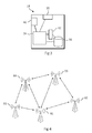
- Figure 1 shows a communications system 2.
- this communications system 2 one or more communication devices 4 can be used for accessing various services and/or applications provided via or within the communication system 2.
- mobile communication devices 4 communicate with an appropriate access node 8 via wireless interfaces 6.
- Access node 8 can be configured to provide a cell, but can also provide, for example, three sectors, each sector providing a cell.
- Each mobile communication device 4 and the access node 8 may have one or more radio channels open at the same time and may receive signals from more than one source.
- the access node 8 is connected to communications network 10.
- a gateway function 12 may be provided to facilitate communications between the communications network 10 and a further communications network 10'.
- the other network 10' may be any appropriate network.
- the other network 10' may be another communication network, such as the one shown, containing an access node 8' and communications devices 4' connected via wireless interfaces 6'.
- the other network 10' may be a packet data network such as the Internet.
- the communication system 2 may thus be provided with one or more interconnected networks 10, 10' and the elements thereof.
- An access node 8 may communicate with one or more network entities 14 within the communications network 10. These network entities 14 may be interconnected within the communications network 10. Each of the network entities 14 may be a single unit, or may have its functions distributed over a plurality of units. The network entities 14 may be assigned different functions, for example one network entity may communicate with other communications networks, such as communications network 10', via gateway 12. A further network entity may be configured to communicate with one or more access nodes 8.
- the network entities 14 may serve to control the access node 8 so as to enable operation thereof and management of the communication devices 4 in communication with the access node 8. However, in certain communication systems such as autonomous systems there may be no control entities.
- Non-limiting examples of appropriate access nodes 8 are an access node of a cellular system, for example what is known as a base station, Node B or enhanced NodeB (eNB) in the vocabulary of the 3GPP specifications.
- Other examples include access nodes of systems that are based on technologies such as wireless local area network (WLAN) and/or WiMax (Worldwide Interoperability for Microwave Access).
- WLAN wireless local area network
- WiMax Worldwide Interoperability for Microwave Access
- the communication devices 4 can communicate with the access node 8 using various access techniques, such as code division multiple access (CDMA), or wideband CDMA (WCDMA).
- CDMA code division multiple access
- WCDMA wideband CDMA
- the latter technique is used by communication systems based on the third Generation Partnership Project (3GPP) specifications.
- 3GPP third Generation Partnership Project
- Other examples include time division multiple access (TDMA), frequency division multiple access (FDMA), space division multiple access (SDMA) and so on.
- LTE long-term evolution
- UMTS Universal Mobile Telecommunications System
- 3GPP 3rd Generation Partnership Project
- OFDMA orthogonal frequency divisional multiple access
- SC-FDMA SC-FDMA
- the access node 8 may comprise one or more antennas 16 connected to control apparatus 18.
- the antenna 16 may communicate with communication devices 4 via wireless interfaces 6.
- the control unit 18 may perform a plurality of functions to facilitate the communications with both the communications devices 4 and the network 10. The functionality of the control unit 18 of the access node 8 will be described in more detail with reference to figure 3 .
- FIG. 2 shows a schematic, partially sectioned view of a communication device 4 that can be used for communication with an access node 8 within the communication system 2.
- An appropriate communication device 4 may be provided by any device capable of sending and receiving radio signals. Non-limiting examples include a mobile station (MS), a portable computer provided with a wireless interface card or other wireless interface facility, personal data assistant (PDA) provided with wireless communication capabilities, or any combinations of these or the like.
- MS mobile station
- PDA personal data assistant
- a mobile communication device may be used for voice and video calls, for accessing service applications and so on.
- the communications device 4 may transmit and receive signals over an air interface 6 via a transceiver, designated schematically by block 20.
- the transceiver may be provided for example by means of one or more radio parts and one or more associated antenna arrangements.
- the antenna arrangements may be arranged internally or externally to the communications device 4.
- the communications device 4 may also be provided with at least one data processing entity 22, at least one memory 24 and other possible components 26 for use in software aided execution of tasks it is designed to perform, including control of access to and communications with access systems.
- the data processing, storage and other relevant control apparatus can be provided on an appropriate circuit board and/or in chipsets. This feature is denoted by reference 28.
- the user may control the operation of the mobile device by means of a suitable user interface such as key pad 30, voice commands, touch sensitive screen or pad, combinations thereof or the like.
- a display 32, a speaker and a microphone are also typically provided.
- a mobile communication device may comprise appropriate connectors (either wired or wireless) to other devices and/or for connecting external accessories, for example hands-free equipment, thereto.
- FIG. 3 shows an example of a control apparatus 18 for an access node 8.
- the control apparatus 18 may be configured to implement some of the embodiments of the invention.
- the control apparatus 18 may contain a processor 34 connected to a memory 36.
- the processor may perform some of the functions of the invention based on computer instructions contained in the computer readable memory 36.
- the processor 34 may be connected to an wireless interface unit 38 for communicating with the antenna 16 (not shown in Figure 3 ) of the access node 8.
- the wireless interface unit 38 may comprise a transceiver unit capable of performing signal processing required for communication over the air interface with communications devices 4.
- the control apparatus 18 of the access node 8 is able to communicate with the communication devices 4 via the antenna 16. Alternatively or additionally the control apparatus 18 may communicate with other access nodes via the antenna 16.
- control apparatus 18 may comprise a network interface unit 40 connected to processor 34 for communicating with the network 10. This communication with the network 10 may be via a fixed network or via a wireless link.
- the control apparatus 18 of the access node 8 may communicate with other access nodes via the network 10.
- the control apparatus 18 may further be provided with a dedicated processor 42.
- the dedicated processor 42 may be connected to the processor 34, the memory 36 and any other units within the control apparatus 18 so that it may perform its function.
- the dedicated processor 42 may be optimized for performing certain processor intensive tasks such as digital signal processing.
- the dedicated processor 42 may be designed to perform certain low level tasks, such as memory arbitration.
- control apparatus 18 for an access node 8 is purely exemplary and functional. As such there may be provided more than one of any of the processor 34, memory 36, interface units 38 and 40 and dedicated processor 42. Equally these element may be interconnected in any manner required for them to perform their function.
- Figure 4 shows an arrangement of access nodes 81, 82, 83, 84 and 85. It will be understood that the five access nodes present are only exemplary and more or fewer access nodes may be present in alternative embodiments of the invention.
- the lines connecting the access nodes 81-85 represent a strong interference bonding between the access nodes. It can be seen that access node 81 has a strong interference bonding with all four of the other access nodes. By contrast, access node 82 has strong interference bonding with only access node 81 and 83. Access node 83 has strong interference bonding with access nodes 81, 82 and 84. Access node 84 has strong interference bonding with access nodes 81, 85 and 83. Finally access node 85 has strong interference bonding with access nodes 81 and 84.
- Interference bonding represents the level of interference between the two access nodes.
- interference bonding represents the amount which the signalling associated with one access node may affect the signalling of a further node in case of simultaneous transmission using the same resource.
- the interference bonding may be measured in terms of the SINR, or by any other relevant measurement.
- Strong interference bonding is used to represent the condition that the interference bonding between two access nodes is above a certain threshold. This threshold may be predetermined, or calculated from other network parameters.
- strong inference bonding may represent the condition that the interference bonding is such that the spectral efficiency of the two nodes (that is the amount of data that can be transmitted and received over the air interface by the two access nodes) is higher if they split the resource into two orthogonal halves (e.g. in time), one for each node, rather than both using integral resource simultaneously.
- the aggregate spectral efficiency of the two access nodes using the same (and therefore interfering) component carrier may be less than the aggregate spectral efficiency of both nodes using a component carrier without interference for half of the time.
- a different measure of strong interference bonding may be used.
- a strong interference bond is determined by a bidirectional relation between two access nodes. Let two neighbour access nodes be denoted by eNB-A and eNB-B. If eNB-A and eNB-B are the only ones sharing a particular resource, the expected SINR is given by the BIM matrix values.
- the estimations rely on the BIM and may include a priori characterization of system level performance as described in, for example, P. Mogensen, W. Na, I. Kovács, et al., "LATE Capacity compared to the Shannon Bound", IEEE VTC2007-Spring, pp. 1234-1238, 2007 .
- the smallest SINR value found in the BIM from/towards the neighbouring cell may be used as input to the Shannon-like formula described in the document referenced above.
- This general method facilitates low-complexity yet effective predictions of the spectral efficiency of any cell given the perceived SINR.
- the information both cells see is identical given the way the BIM is created in this embodiment.
- the spectral efficiency of the whole is higher if each access node uses a orthogonal share of the original resource. Otherwise, if the SINR values are high, the spectral efficiency is higher if the two access nodes simply reuse the resources, that is, use the same component carrier without any restrictions.
- the BIM is used to estimate the SINR and the SINR is used to determine the degree of interference bonding.
- the SINR is used to determine the degree of interference bonding.
- any other suitable measurements may be used.
- the BIM, SINR or other measurements may be stored in the memory 36 as shown in Figure 3 .
- the information may be received from any appropriate entity in the network.
- the background interference matrix (BIM) is described in 3GPP Tdoc R1-090235, "Use of Background Interference Matrix for Autonomous Component Carrier Selection for LTE-Advanced", Nokia Siemens Networks, Nokia.
- embodiments of the invention propose creating coalitions of access nodes. These coalitions of access nodes may use the same component carrier or carriers, but form a coalition so as to use the component carrier in a non-interfering, that is orthogonal, manner. This may maximize the spectral efficiency of the air interface.
- the component carrier(s) may be shared by the access nodes within a coalition using a form of time division access. That is, one access node will be able to use the component carrier for a specified period, and then the component carrier will be made available to one or more of the other access nodes within the coalition.
- Alternative mechanisms for sharing the component carrier between the access nodes of a coalition may be used.
- the access nodes may signal to each other to coordinate the sharing of the resources in the coalition.
- the nature of the coalition that is the identities of the access nodes within it and the component carriers which may be used by an individual access node may be stored in the memory 36.
- a coalition table may be stored for each access node.
- Each access node may keep a coalition table for each allocated SCC, containing the list of current coalitions and the corresponding allocation restrictions.
- the access nodes are able to communicate with each other to form and break down these coalitions.
- This signalling may be done over the air interface, that is via wireless interface 38, or via a fixed network, that is via network interface 40.
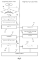
- an access node determines whether it requires additional capacity, that is, one or more additional component carriers to communicate over. This decision block is self looping until the determination is true. As described above, the component carriers are considered shared resources, since they may be used by any access node.
- step S1 having determined that additional capacity is required, the originating access determines which neighbouring access nodes have a strong interference bonding with the originating access node.
- This step may include accessing information stored in memory 36 such as the SINR or BIM. Alternatively this step may include receiving information via one or more of the interfaces.
- step S2 the originating access node selects one or more component carriers to form the basis of one or more coalitions.
- the one or more component carriers may be shared, so that the use of the resources is orthogonal, that is non-interfering.
- the component carriers may be selected by a number of different methods. In some embodiments the component carriers may be selected based on the number of interfering neighbouring access nodes which do, or do not, use those component carriers. Alternatively, if the component carriers encompass different bandwidths, the selection may be based on the available bandwidth in the component carrier(s).
- the originating access node will communicate (and therefore form coalitions) with all neighbouring access nodes with which there is a strong interference bond.
- the originating access node may only communicate with those neighbouring access nodes which are using the selected component carrier(s).
- interfering neighbouring access nodes with which the originating access node communicates will henceforth be identified as interfering neighbouring access nodes.
- interfering neighbouring access nodes For simplicity, in Figure 5 , only one interfering neighbouring access node is shown. However, embodiments of the invention will include situations where there is more than one interfering neighbouring access node. Equally, reference below to the interfering neighbouring access node in either the plural or singular is intended to encompass situations with any number of interfering neighbouring access nodes.
- a coalition formation request message (CFR) is sent by the originating access node to the interfering neighbouring access nodes determined in step S1.
- Each coalition formation request message may include the identification of the originating access node, the identification of the interfering neighbouring access nodes and an identification of one or more selected component carriers.
- the CFR may be sent to all of the interfering neighbouring access nodes. Alternatively, the CFR may be sent to only those interfering neighbouring access nodes which are using the selected resources, i.e. the selected component carrier(s).
- step S4 the coalition formation requests are received by the interfering neighbouring access nodes.
- step S5 the interfering neighbouring access nodes determine the extent of any existing coalitions that they are a part of. This may include determining what resource restrictions are already in place due to these existing coalitions. Equally the interfering neighbouring access nodes may determine if they form a coalition with the other interfering neighbouring access nodes identified in the CFR.
- step S6 coalition formation reply messages (CFY) are sent by the interfering neighbouring access nodes to the originating access node.
- Each coalition formation reply message may include the identification of the interfering neighbouring access node sending the CFY, the identification of the originating access node, the resource restriction set by existing coalitions which the interfering neighbouring access node sending the CFY is a part of and an indication of whether any of the interfering neighbouring access nodes identified in the CFY are already part of a coalition.
- step S7 the originating access node receives the CFYs.
- step S8 the originating access node determines a new allocation for the resources. This step is expanded on in more detail below.
- step S9 coalition formation acknowledgment messages (CFA) are sent from the originating access node to the interfering neighbouring access nodes.
- the CFA contains the identification of the originating access node, the identification of the interfering neighbouring access nodes, the new coalitions formed and the new resource division.
- step S10 the CFAs are received at the interfering neighbouring access nodes.
- step S11 the access nodes update their coalition formation tables, according to the allocation determined in step S8.
- the CFA may be sent to only a subset of the interfering neighbouring access nodes. This may be because one or more of the interfering neighbouring access nodes is unaffected by the new allocations and therefore does not require a CFA. Equally the CFA may be sent to more than just the interfering neighbouring access nodes since the new allocations may affect access nodes beyond the interfering neighbouring access nodes, for example when the interfering neighbouring access nodes are part of a coalition themselves.
- an interfering neighbouring access node when an interfering neighbouring access node receives a CFA message, it may broadcast the changes in allocation and coalitions (specified in the CFA message) to the access nodes with which it forms coalitions. These access nodes may not form coalitions with the originating access node, and therefore may not have received the CFA.
- the messages sent may be acknowledged by the receiver (these messages are not shown in Figure 5 ).
- the acknowledgement messages may be a 200OK message or any similar message dependent on the signalling protocol used.
- step S8 The determination of the new allocation in step S8 has been described as being performed by the originating access node. However this determination can be done by any relevant entity.
- the above method may be adapted to include a control node.
- This control node may receive the CFR from the access node, and respond using the CFA.
- the control node may send out its own CFR messages to the interfering neighbouring access nodes, and receive CFY messages from them.
- the control node may store the information on existing coalitions and the like and therefore is not required to communicate with the interfering neighbouring access nodes before determining the new allocation.
- control node may be provided with information regarding the resource needs and usage of one or more of the access nodes, and be able to change the allocation of the shared resources without receiving a CFR. In this case, only a CFA message changing the allocations of access nodes may be sent.
- an access node is shown performing the tasks of the originating access node as described above with reference to Figure 5 .
- the other access nodes shown are either interfering neighbouring access nodes as described above, or are access nodes which while not interfering with the originating access node, are part of coalitions formed with the one or more interfering neighbouring access nodes.
- the white access nodes represent the originating access node and is provided with the reference numeral 44.
- the black access nodes represent the interfering neighbouring access nodes and are provided with the reference numerals 46 and 46' as applicable.
- the checked access nodes represent other access nodes which do not have a strong interference bond with the originating access node, that is they are not interfering neighbouring access nodes. These nodes are shown since they may form coalitions with one or more of the interfering neighbouring access nodes and are provided with reference numerals 48 and 48' as applicable.
- each access node is shown with a row of six boxes near them .
- These boxes are a schematic representation of the shared resources allocated to that access node.
- Each box represents a shared resource allocation, such as a portion of a single component carrier.
- the position of the box in the row represents a different portion. For example the left most box in each series represents the same portion.
- a shaded box represents that that portion is being used by the respective access node.
- An un-shaded box represents that that particular component carrier is not being used by the respective access node.
- six portions of the component carrier are shown, it will be apparent that this is only exemplary and that more or fewer portions may be used. Equally, in some embodiments, the portions may span more than one component carrier, that is the portions of the shared resources are not limited to one component carrier.
- the six portions generally relate to a secondary component carrier as described above. That is, the primary component carriers used by each access node are not shown. This does not preclude embodiments of the invention including a step in which primary component carriers are re-allocated.
- FIGS 7 to 12 show the CFR being sent as a dashed line.
- the response CFY and allocation message CFA as described above are not shown, however they are assumed to exist.
- a coalition is represented by a solid line. Where the coalition is formed of three access nodes, the line is shown as three lines connected at a central point.
- Figures 7a and 7b shows the case where there is only one interfering neighbouring access node.
- the originating access node 44 has no allocation of the resources, while interfering neighbouring access node 46 has full allocation of the resources.
- the access node 44 sends a CFR to access node 46.
- Figures 8a and 8b show the situation where there is only one interfering neighbouring access node 46, but that one neighbouring interfering access node already forms a coalition with two other access nodes 48 and 48'.
- the originating access node 44 sends the CFR request to only the interfering neighbouring access node 46, and receives a response from this one interfering neighbouring access node 46 accordingly.
- This scenario may be identified as a "free rider" situation, because the originating access node 44 is then allocated as many resources as is possible respecting the allocation of the one interfering neighbouring access node 46.
- This is shown in Figure 4b . It will be apparent that in forming the coalition between the originating access node 44 and the interfering neighbouring access node 46, the coalition between the interfering neighbouring access node 46 and the other nodes 48 and 48' is unchanged. In general, a node is allowed to extend its resource allocation if this extension is possible respecting the allocation of all interfering neighbouring access nodes.
- Figures 9a and 9b show a situation in which there are two interfering neighbouring access nodes 46 and 46' which are already forming a coalition.
- the originating access node 44 sends a CFR to both interfering neighbouring access nodes 46 and 46'.
- the CFY is received from both interfering neighbouring access nodes and the CFA is again sent to both nodes.
- the originating access node 44 augments the coalition of the interfering neighbouring access nodes 46 and 46'.
- the cardinality of the resultant coalition is three. In this case, the resources are divided equally amongst the three access nodes.
- Figures 10a and 10b show a situation in which there are two interfering neighbouring access nodes 46 and 46'. In addition, these two interfering neighbouring access nodes 46 and 46' form a coalition of cardinality three with a further access node 48.
- the CFR is again sent to both interfering neighbouring access nodes 46 and 46', the CFY received from the same two nodes, and the CFA is sent to both nodes.
- the resulting coalition, of cardinality three, between the originating access node 44 and the two interfering neighbouring access nodes 46 and 46' has spare capacity in the form of the capacity allocated to the further access node 48. This capacity can be allocated to the originating access node 44.
- the situation is similar to the "free rider" situation described above in relation to Figures 8a and 8b in so far as the originating access node 44 is able to use the resources which the interfering neighbouring access nodes 46 and 46' are restricted from use due to their existing coalitions.
- Figures 11a and 11b show a situation in which there are two interfering neighbouring access nodes 46 and 46' which are not part of the same coalition. Instead, interfering neighbouring access node 46 forms a coalition with access node 48, and interfering neighbouring access node 46' is not part of a coalition, that is it forms a coalition of cardinality one with itself.
- two coalitions need to be made.
- Each individual coalition may be considered in a similar manner to the augmentation described above with relation to Figures 7a and 7b .
- the originating access node will allocate resources so that each access node is allocated half the available resources.
- the originating node 44 is responsible of making its own allocation compatible with the allocations of nodes 46 and 46' in order to maximize the spectral efficiency.
- FIGs 12a and 12b show the situation in which there are two interfering neighbouring access nodes 46 and 46'.
- Each interfering neighbouring access node is part of a coalition with a further access node, 48 and 48' respectively.
- the restrictions of the existing coalitions on the interfering neighbouring access nodes 46 and 46' mean that the available resources cannot be simply divided in half.
- the originating access node forms two coalitions of cardinality two with the interfering neighbouring access nodes 46 and 46'
- the resources are divided equally amongst the three access nodes. If the nodes 48 and 48' do not have any further restrictions they are allowed to extend their allocations according to the same rules described in the "free rider" situation, exemplified in Figures 8a and 8b .
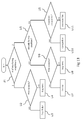
- step U1 a determination is made as to the number of interfering neighbouring access nodes.
- step U2 If there is only one interfering neighbouring access node, it is determined in step U2 if the potential new coalition with the one interfering neighbouring access node has spare capacity.
- step U5 it is determined whether the two interfering neighbouring access nodes form a coalition.
- step U6 it is determined whether there is free capacity in that coalition. If there is free capacity, then the situation is like that as described in relation to Figures 10a and 10b and referenced by U7. If there is no free capacity, then the situation is like that as described in relation to Figures 9a and 9b and referenced by U8.
- step U5 it is determined that the two interfering neighbouring access nodes do not form a coalition then in step U9 it is determined whether the two potential new coalitions with the two interfering neighbouring access nodes respectively are compatible.
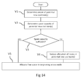
- Step S8 A general method for deciding allocations of resources will be described with reference to Figure 14 .
- This step can be considered an expansion of Step S8 described in Figure 5 .
- step V1 the originating access node, having received the CFYs from the relevant interfering neighbouring access nodes will determine what potential new coalitions will need to be formed.
- the originating access node will attempt to form coalitions (i.e. potential new coalitions) with all interfering neighbouring access nodes as defined above in relation to Figure 5 .
- the originating access node will select only a subset of the interfering neighbouring access nodes to form coalitions with.
- the originating access node determines if there is any free capacity in these potential new coalitions.
- Free capacity represents that a resource (e.g. a portion of a component carrier) is available to be used by the originating access node. That is, none of the other interfering neighbouring access nodes are already using the resource.
- step V3 the originating access node determines whether this free capacity, if any, is sufficient. If the free capacity is sufficient, then the originating access node will proceed directly to step V5. If not, then the originating access node will proceed to step V4.
- step V4 the originating access node will deduct capacity from the interfering neighbouring access nodes so as to create free capacity. This deduction of capacity may be done equally (that is each interfering access node has an equal amount of its allocation deducted), as illustrated in, for example, Figures 9a and 9b and Figures 12a and 12b .
- the deduction of capacity may not be equal.
- An example of this is shown in Figures 11a and 11b where the resource blocks are deducted from interfering neighbouring access node 46' only. In this example the resource blocks are not deducted from interfering neighbouring access node 46.
- step V5 the originating access node allocates the free capacity to itself, and informs the interfering neighbouring access nodes of the new coalition(s) and allocations.
- the free capacity may have been created in step V4 or already present as discussed in step V3.
- an access node (henceforth the dissolving access node) determines that the additional capacity is no longer required, that is that one or more of the component carriers used by the dissolving access node is no longer needed based on the traffic at the dissolving access node.
- This decision block is self looping until the determination is true.
- the dissolving access node may be the originating access node as mentioned with reference to Figure 5 , however it will be understood that it might be any access node in the coalition. Equally the coalition access node may represent any access node forming a coalition with the dissolving access node. As before, a single coalition access node is shown, however this may represent more than one access node.
- step T1 having determined that the additional capacity is no longer required, dissolving access node sends a message to the other members of the coalition dissolving the coalition.
- step T2 the message is received by the other members of the coalition.
- step T3 the members of the coalition dissolve the coalition and reallocate their resources accordingly.
- the required data processing and functionality of the access node, control entity or any further apparatus described above may be provided by means of one or more processors.
- the above described functions may be provided by separate processors or by an integrated processor.
- the data processing may be distributed across several data processing modules.
- a data processor may be provided by means of, for example, at least one chip or a chipset. Appropriate memory capacity can also be provided in the relevant nodes.
- An appropriately adapted computer program code product or products may be used for implementing the embodiments, when loaded on an appropriate data processing apparatus, for example in a processor apparatus associated with the base station and /or processing apparatus associated with relay node.
- the program code product for providing the operation may be stored on, provided and embodied by means of an appropriate carrier medium.
- An appropriate computer program can be embodied on a computer readable record medium. A possibility is to download the program code product via a data network.
- E-UTRAN Evolved Universal Terrestrial Radio Access Network
- the eNBs may provide E-UTRAN features such as user plane Radio Link Control/Medium Access Control/Physical layer proto- col (RLC/MAC/PHY) and control plane Radio
- RRC Resource Control
Landscapes
- Engineering & Computer Science (AREA)
- Computer Networks & Wireless Communication (AREA)
- Signal Processing (AREA)
- Mobile Radio Communication Systems (AREA)
Claims (22)
- Verfahren, das Folgendes umfasst:Auswählen eines oder mehrerer zusätzlicher Komponententräger durch einen ersten Knoten (44), wobei die Ressourcen des ausgewählten einen oder der ausgewählten mehreren Komponententräger mit einem oder mehreren zweiten Knoten (46, 46') gemeinsam verwendet werden;Bestimmen der Identität mindestens eines des einen oder der mehreren zweiten Knoten (46, 46'), zu dem der erste Knoten (44) eine Störungsbindung mit einer Stärke über einem vorbestimmten Schwellenwert für die gemeinsam verwendeten Komponententrägerressourcen aufweist;Senden einer Anforderung von Informationen bezüglich der Nutzung der gemeinsam verwendeten Komponententrägerressourcen an den mindestens einen zweiten Knoten (46, 46'), wobei die Anforderung eine Angabe des ausgewählten einen oder der ausgewählten mehreren Komponententräger umfasst;Empfangen einer Antwort von dem mindestens einen zweiten Knoten (46, 46'), wobei die Antwort Informationen bezüglich mindestens einer bestehenden Vereinigung des mindestens einen zweiten Knotens (46, 46') mit Bezug auf den angegebenen einen oder die angegebenen mehreren Komponententräger umfasst, wobei die Nutzung der gemeinsam verwendeten Komponententrägerressourcen nicht störend innerhalb jeder Vereinigung von Knoten ist;Bestimmen durch den ersten Knoten (44), wie die gemeinsam verwendeten Komponententrägerressourcen momentan dem mindestens einen zweiten Knoten (46, 46') zugewiesen sind;Bestimmen einer neuen Zuweisung von gemeinsam verwendeten Komponententrägerressourcen durch den ersten Knoten (44) mit Bezug auf die mindestens eine bestehende Vereinigung des mindestens einen zweiten Knotens (46, 46'); undVeranlassen, dass mindestens eine Zuweisungsnachricht, die die neue Zuweisung beinhaltet, an den mindestens einen zweiten Knoten (46, 46') gesendet wird, wobei die Zuweisungsnachricht eine Angabe, dass mindestens ein Teil der gemeinsam verwendeten Komponententrägerressourcen, die vom mindestens einen zweiten Knoten (46, 46') genutzt werden, dem ersten Knoten zugewiesen wurde, und eine Angabe, dass eine oder mehrere neue Vereinigungen zwischen dem ersten Knoten (44) und dem mindestens einen zweiten Knoten (46, 46') gebildet werden, umfasst.
- Verfahren nach Anspruch 1, wobei die Stärke der Störungsbindung durch Nutzung der Werte des wahrgenommenen Signal/Interferenz-plus-Rausch-Verhältnisses berechnet wird.
- Verfahren nach Anspruch 1 oder 2, wobei der erste Knoten (44) eine Vereinigung mit dem mindestens einen zweiten Knoten (46, 46') basierend auf in der mindestens einen Zuweisungsnachricht gesendeten Informationen bildet.
- Verfahren nach einem der Ansprüche 1 bis 3, wobei die Antwort Folgendes umfasst:Informationen bezüglich dessen, welche gemeinsam verwendeten Komponententrägerressourcen gerade von dem mindestens einen zweiten Knoten (46, 46') genutzt werden; und/oderInformationen bezüglich dessen, welche gemeinsam verwendeten Komponententrägerressourcen, die von dem mindestens einen zweiten Knoten (46, 46') genutzt werden, dem ersten Knoten (44) zugewiesen werden können; und/oderInformationen bezüglich dessen, ob der mindestens eine zweite Knoten (46, 46') eine Vereinigung mit einem oder mehreren weiteren Knoten (48) bildet.
- Verfahren nach einem vorhergehenden Anspruch, das Folgendes umfasst:Empfangen von Informationen, die eine Störungsbindung zwischen dem ersten Knoten (44) und dem mindestens einen zweiten Knoten (46, 46') definieren;Ablegen der empfangenen Informationen in einem Speicher, wobei das Bestimmen der Identität mindestens eines zweiten Knotens (46, 46') das Auslesen von Informationen aus dem Speicher umfasst.
- Verfahren nach einem vorhergehenden Anspruch, wobei eine Störungsbindung den Betrag darstellt, um den die mit der gemeinsam verwendeten Komponententrägerressource und dem mindestens einen zweiten Zugangsknoten (46, 46') assoziierte Signalisierung sich auf die mit der gemeinsam verwendeten Komponententrägerressource und dem ersten Knoten (44) assoziierte Ressource auswirkt.
- Verfahren nach einem vorhergehenden Anspruch, wobei der erste Knoten (44) eine starke Störungsbindung zu dem mindestens einen des einen oder der mehreren zweiten Knoten (46, 46') aufweist, wobei die starke Störungsbindung angibt, dass aufgrund der Störungsbindung eine gleichzeitige Nutzung der gemeinsam verwendeten Komponententrägerressource durch den ersten (44) und den mindestens einen zweiten Knoten (46, 46') weniger effizient wird als eine koordinierte Nutzung der gemeinsam verwendeten Komponententrägerressource.
- Verfahren nach einem vorhergehenden Anspruch, wobei die gemeinsam verwendeten Komponententrägerressourcen Abschnitte von Komponententrägern umfassen und wobei die Abschnitte von Komponententrägern im Zeitbereich orthogonal sind.
- Verfahren nach einem vorhergehenden Anspruch, wobei der mindestens eine zweite Knoten zwei zweite Knoten (46 und 46') umfasst und wobei dem ersten Knoten (44) ein erster Teil der gemeinsam verwendeten Komponententrägerressourcen zugewiesen wird, einem zweiten Knoten (46) ein zweiter Teil der gemeinsam verwendeten Komponententrägerressourcen zugewiesen wird und einem weiteren zweiten Knoten (46') ein dritter Teil der gemeinsam verwendeten Komponententrägerressourcen zugewiesen wird.
- Computerprogrammprodukt, das in einem computerlesbaren Medium ausgeführt ist, welches computerlesbare Anweisungen enthält, die, wenn sie in einem oder mehreren Prozessoren durchgeführt werden, das Verfahren nach einem vorhergehenden Anspruch durchführen.
- Einrichtung, die Folgendes umfasst:Auswahlmittel zum Auswählen eines oder mehrerer zusätzlicher Komponententräger durch einen ersten Knoten (44), wobei die Ressourcen des ausgewählten einen oder der ausgewählten mehreren Komponententräger mit einem oder mehreren zweiten Knoten (46, 46') gemeinsam verwendet werden;Bestimmungsmittel zum Bestimmen der Identität mindestens eines des einen oder der mehreren zweiten Knoten (46, 46'), zu dem der erste Knoten (44) eine Störungsbindung mit einer Stärke über einem vorbestimmten Schwellenwert für die gemeinsam verwendeten Komponententrägerressourcen aufweist; undMittel zum Senden einer Anforderung von Informationen bezüglich der Nutzung der gemeinsam verwendeten Komponententrägerressourcen an den mindestens einen zweiten Knoten (46, 46'), wobei die Anforderung eine Angabe des ausgewählten einen oder der ausgewählten mehreren Komponententräger umfasst;Mittel zum Empfangen einer Antwort von dem mindestens einen zweiten Knoten (46, 46'), wobei die Antwort Informationen bezüglich mindestens einer bestehenden Vereinigung des mindestens einen zweiten Knotens (46, 46') mit Bezug auf den ausgewählten einen oder die ausgewählten mehreren Komponententräger umfasst, wobei die Nutzung der gemeinsam verwendeten Komponententrägerressourcen nicht störend innerhalb jeder Vereinigung von Knoten ist;Mittel zum Bestimmen durch den ersten Knoten (44), wie die gemeinsam verwendeten Komponententrägerressourcen momentan dem mindestens einen zweiten Knoten (46, 46') zugewiesen sind;Bestimmungsmittel zum Bestimmen einer neuen Zuweisung von gemeinsam verwendeten Komponententrägerressourcen mit Bezug auf die mindestens eine bestehende Vereinigung des mindestens einen zweiten Knotens (46, 46') durch den ersten Knoten (44); undMittel zum Veranlassen, dass mindestens eine Zuweisungsnachricht, die die neue Zuweisung beinhaltet, an den mindestens einen zweiten Knoten (46, 46') gesendet wird, wobei die Zuweisungsnachricht eine Angabe, dass mindestens ein Teil der gemeinsam verwendeten Komponententrägerressourcen, die vom mindestens einen zweiten Knoten (46, 46') genutzt werden, dem ersten Knoten (44) zugewiesen wurde, und eine Angabe, dass eine oder mehrere neue Vereinigungen zwischen dem ersten Knoten (44) und dem mindestens einen zweiten Knoten (46, 46') gebildet werden, umfasst.
- Einrichtung nach Anspruch 11, wobei der erste Knoten (44) konfiguriert ist, um eine Vereinigung mit dem mindestens einen zweiten Knoten (46, 46') basierend auf in der mindestens einen Zuweisungsnachricht gesendeten Informationen zu bilden.
- Einrichtung nach einem der Ansprüche 11 bis 12, wobei die Antwort Folgendes umfasst:Informationen bezüglich dessen, welche gemeinsam verwendeten Komponententrägerressourcen gerade von dem mindestens einen zweiten Knoten (46, 46') genutzt werden; und/oderInformationen bezüglich dessen, welche gemeinsam verwendeten Komponententrägerressourcen, die von dem mindestens einen zweiten Knoten (46, 46') genutzt werden, dem ersten Knoten (44) zugewiesen werden können; und/oderInformationen bezüglich dessen, ob der mindestens eine zweite Knoten (46, 46') eine Vereinigung mit einem oder mehreren weiteren Knoten (48) bildet.
- Einrichtung nach einem der Ansprüche 11 bis 13, die Folgendes umfasst:Mittel zum Empfangen von Informationen, die eine Störungsbindung zwischen dem ersten Knoten (44) und dem mindestens einen zweiten Knoten (46, 46') definieren;einen Speicher zum Ablegen der empfangenen Informationen, wobei das Bestimmungsmittel Mittel zum Auslesen der Informationen aus dem Speicher umfasst.
- Einrichtung nach einem der Ansprüche 11 bis 14, wobei eine Störungsbindung den Betrag darstellt, um den die mit der gemeinsam verwendeten Komponententrägerressource und dem mindestens einen zweiten Zugangsknoten (46, 46') assoziierte Signalisierung sich auf die mit der gemeinsam verwendeten Komponententrägerressource und dem ersten Knoten (44) assoziierte Ressource auswirkt.
- Einrichtung nach einem der Ansprüche 11 bis 15, wobei der erste Knoten (44) eine starke Störungsbindung zu dem mindestens einen des einen oder der mehreren zweiten Knoten (46, 46') aufweist, wobei die starke Störungsbindung angibt, dass aufgrund der Störungsbindung eine gleichzeitige Nutzung der gemeinsam verwendeten Komponententrägerressource durch den ersten (44) und den mindestens einen zweiten Knoten (46, 46') weniger effizient wird als eine koordinierte Nutzung der gemeinsam verwendeten Komponententrägerressource.
- Einrichtung nach einem der Ansprüche 11 bis 16, wobei die gemeinsam verwendeten Komponententrägerressourcen Abschnitte von Komponententrägern umfassen und wobei die Abschnitte von Komponententrägern im Zeitbereich orthogonal sind.
- Einrichtung nach einem der Ansprüche 11 bis 17, wobei der mindestens eine zweite Knoten zwei zweite Knoten (46 und 46') umfasst und wobei dem ersten Knoten (44) ein erster Teil der gemeinsam verwendeten Komponententrägerressourcen zugewiesen wird, einem zweiten Knoten (46) ein zweiter Teil der gemeinsam verwendeten Komponententrägerressourcen zugewiesen wird und einem weiteren zweiten Knoten (46') ein dritter Teil der gemeinsam verwendeten Komponententrägerressourcen zugewiesen wird.
- Einrichtung nach einem der Ansprüche 11 bis 18, wobei der erste Knoten (44) und der mindestens eine zweite Knoten (46, 46') eNodeBs umfassen.
- Verfahren, das Folgendes umfasst:Empfangen einer Anforderung von Informationen bezüglich einer Nutzung von Ressourcen auf einem oder mehreren Komponententrägern, die in der Anforderung angegeben sind, durch einen zweiten Knoten (46, 46') von einem ersten Knoten (44), wobei die Ressourcen des angegebenen einen oder der angegebenen mehreren Komponententräger mindestens vom ersten Knoten (44) und vom zweiten Knoten (46, 46') gemeinsam verwendet werden und der zweite Knoten (46, 46') eine Störungsbindung über einem vorbestimmten Störungsstärkeschwellenwert zu dem ersten Knoten (44) für die gemeinsam verwendeten Komponententrägerressourcen aufweist;Senden einer Antwort an den ersten Knoten (44), wobei die Antwort Informationen bezüglich mindestens einer bestehenden Vereinigung des zweiten Knotens (46, 46') mit Bezug auf den angegebenen einen oder die angegebenen mehreren Komponententräger umfasst, wobei die Nutzung der gemeinsam verwendeten Komponententrägerressourcen nicht störend innerhalb jeder Vereinigung von Knoten ist;Empfangen einer Zuweisungsnachricht, die eine neue Zuweisung von Ressourcen für den gemeinsam verwendeten einen oder die gemeinsam verwendeten mehreren Komponententräger beinhaltet, vom ersten Knoten (44), wobei die Zuweisungsnachricht weiter eine Angabe, dass mindestens ein Teil der gemeinsam verwendeten Komponententrägerressourcen, die vom zweiten Knoten (46, 46') genutzt werden, dem ersten Knoten (44) zugewiesen wurde, und eine Angabe, dass eine oder mehrere neue Vereinigungen zwischen dem ersten Knoten (44) und mindestens einem zweiten Knoten (46, 46') gebildet werden, umfasst; undAktualisieren einer Vereinigungsbildungstabelle basierend auf der empfangenen Zuweisungsnachricht.
- Computerprogrammprodukt, das in einem computerlesbaren Medium ausgeführt ist, welches computerlesbare Anweisungen enthält, die, wenn sie in einem oder mehreren Prozessoren durchgeführt werden, das Verfahren nach Anspruch 20 durchführen.
- Einrichtung, die Folgendes umfasst:Empfangsmittel zum Empfangen einer Anforderung von Informationen bezüglich einer Nutzung von Ressourcen auf einem oder mehreren Komponententrägern, die in der Anforderung angegeben sind, durch einen zweiten Knoten (46, 46') von einem ersten Knoten (44), wobei die Ressourcen des angegebenen einen oder der angegebenen mehreren Komponententräger mindestens vom ersten Knoten (44) und vom zweiten Knoten (46, 46') gemeinsam verwendet werden und der zweite Knoten (46, 46') eine Störungsbindung über einem vorbestimmten Störungsstärkeschwellenwert zu dem ersten Knoten (44) für die gemeinsam verwendeten Komponententrägerressourcen aufweist;Sendemittel zum Senden einer Antwort an den ersten Knoten (44), wobei die Antwort Informationen bezüglich mindestens einer bestehenden Vereinigung des zweiten Knotens (46, 46') mit Bezug auf den angegebenen einen oder die angegebenen mehreren Komponententräger umfasst, wobei die Nutzung der gemeinsam verwendeten Komponententrägerressourcen nicht störend innerhalb jeder Vereinigung von Knoten ist;Empfangsmittel zum Empfangen einer Zuweisungsnachricht, die eine neue Zuweisung von Ressourcen für den gemeinsam verwendeten einen oder die gemeinsam verwendeten mehreren Komponententräger beinhaltet, vom ersten Knoten (44), wobei die Zuweisungsnachricht weiter eine Angabe, dass mindestens ein Teil der gemeinsam verwendeten Komponententrägerressourcen, die vom zweiten Knoten (46, 46') genutzt werden, dem ersten Knoten zugewiesen wurde, und eine Angabe, dass eine oder mehrere neue Vereinigungen zwischen dem ersten Knoten (44) und mindestens einem zweiten Knoten (46, 46') gebildet werden, umfasst; undAktualisierungsmittel zum Aktualisieren einer Vereinigungsbildungstabelle basierend auf der empfangenen Zuweisungsnachricht.
Applications Claiming Priority (1)
| Application Number | Priority Date | Filing Date | Title |
|---|---|---|---|
| PCT/EP2010/052544 WO2011107140A1 (en) | 2010-03-01 | 2010-03-01 | Communication network and method |
Publications (2)
| Publication Number | Publication Date |
|---|---|
| EP2543209A1 EP2543209A1 (de) | 2013-01-09 |
| EP2543209B1 true EP2543209B1 (de) | 2016-11-30 |
Family
ID=43037723
Family Applications (1)
| Application Number | Title | Priority Date | Filing Date |
|---|---|---|---|
| EP10707879.2A Active EP2543209B1 (de) | 2010-03-01 | 2010-03-01 | Kommunikationsnetzeinrichtungen und verfahren |
Country Status (3)
| Country | Link |
|---|---|
| US (1) | US9071973B2 (de) |
| EP (1) | EP2543209B1 (de) |
| WO (1) | WO2011107140A1 (de) |
Families Citing this family (3)
| Publication number | Priority date | Publication date | Assignee | Title |
|---|---|---|---|---|
| NZ603875A (en) * | 2010-06-28 | 2014-12-24 | Ericsson Telefon Ab L M | Methods and arrangements for reducing the signalling overhead in a wireless communication system using carrier aggregation |
| US10085206B2 (en) * | 2016-03-08 | 2018-09-25 | Wipro Limited | Methods and systems for optimization of cell selection in TD-SCDMA networks |
| US11323886B2 (en) | 2018-03-14 | 2022-05-03 | United States Of America As Represented By The Secretary Of The Air Force | Cooperative target execution system for unmanned aerial vehicle networks |
Family Cites Families (7)
| Publication number | Priority date | Publication date | Assignee | Title |
|---|---|---|---|---|
| US7058040B2 (en) * | 2001-09-21 | 2006-06-06 | Schmidt Dominik J | Channel interference reduction |
| GB0725052D0 (en) * | 2007-12-21 | 2008-01-30 | Fujitsu Lab Of Europ Ltd | Communications system |
| GB2457431A (en) | 2008-01-28 | 2009-08-19 | Fujitsu Lab Of Europ Ltd | Interference mitigation method in a wireless network |
| US8559908B2 (en) * | 2008-06-16 | 2013-10-15 | Qualcomm Incorporated | Jamming graph and its application in network resource assignment |
| US8391882B2 (en) * | 2008-10-22 | 2013-03-05 | Qualcomm Incorporated | Method and system for interference management in a spectrum shared by WAN and femto cells |
| EP2436202B1 (de) * | 2009-05-29 | 2019-08-07 | Nokia Solutions and Networks Oy | Kommunikationsnetzwerk und methode dafür |
| US9198185B2 (en) * | 2010-02-10 | 2015-11-24 | Nokia Solutions And Networks Oy | Mechanism for aggregating uplink interference information for use in multi-carrier systems |
-
2010
- 2010-03-01 WO PCT/EP2010/052544 patent/WO2011107140A1/en not_active Ceased
- 2010-03-01 EP EP10707879.2A patent/EP2543209B1/de active Active
- 2010-03-01 US US13/582,554 patent/US9071973B2/en active Active
Non-Patent Citations (1)
| Title |
|---|
| None * |
Also Published As
| Publication number | Publication date |
|---|---|
| US9071973B2 (en) | 2015-06-30 |
| WO2011107140A1 (en) | 2011-09-09 |
| EP2543209A1 (de) | 2013-01-09 |
| US20130022000A1 (en) | 2013-01-24 |
Similar Documents
| Publication | Publication Date | Title |
|---|---|---|
| EP3777284B1 (de) | Breitbandiger pdcch für unlizenziertes band für new radio | |
| US10548071B2 (en) | System and method for communicating traffic over licensed or un-licensed spectrums based on quality of service (QoS) constraints of the traffic | |
| CN102186247B (zh) | 一种小区间干扰协调的方法和系统 | |
| JP6454014B2 (ja) | 秘匿ノード検出 | |
| US20220217703A1 (en) | Dynamic resource allocation in wireless network | |
| US11234218B2 (en) | Descriptor channel designs for uplink channels in a shared radio frequency spectrum band | |
| EP2429249B1 (de) | Verfahren zur Interferenzkoordination zwischen Zellen in einem zellularen Kommunikationsnetzwerk, Netzwerkelement eines zellularen Kommunikationsnetzwerks und zellulares Kommunikationsnetzwerk | |
| EP3404985A1 (de) | Vollduplex-downlink- und uplink-anweisungen | |
| US10813043B2 (en) | System and method for communicating wireless transmissions spanning both licensed and un-licensed spectrum | |
| US20130107116A1 (en) | Apparatus and Method for Communication | |
| CN115568020B (zh) | 一种资源配置方法、信息发送方法及装置 | |
| US20130336178A1 (en) | TDD Data Transmission on Multiple Carriers with Sub Frames Reserved for Predetermined Transmission Directions | |
| WO2013139041A1 (en) | Device-to-device resource allocation method and apparatus | |
| JP2018501722A (ja) | ライセンスされていない無線周波数スペクトル帯域における送信を管理するための技法 | |
| US20150222546A1 (en) | Load Balancing in Communication Systems | |
| CN105722227B (zh) | 异构网中上行链路控制信道上的干扰减轻 | |
| JP2022548089A (ja) | 動的な物理アップリンク共有チャネルスキップがある場合のアップリンク制御情報多重化 | |
| WO2015166792A1 (ja) | 基地局装置、端末装置、および通信方法 | |
| US9866355B2 (en) | Service aware interference management | |
| EP2543209B1 (de) | Kommunikationsnetzeinrichtungen und verfahren | |
| EP3568940B1 (de) | Gemeinsame pdcch-konfiguration | |
| US11533761B2 (en) | Information processing method and device | |
| WO2013170471A1 (en) | Mechanism for controlling communications using resource co-scheduling in inter-cell interference scenario | |
| US20140016588A1 (en) | Apparatus and Corresponding Method for Allocating a Component Carrier to a Cell in a Communication System |
Legal Events
| Date | Code | Title | Description |
|---|---|---|---|
| PUAI | Public reference made under article 153(3) epc to a published international application that has entered the european phase |
Free format text: ORIGINAL CODE: 0009012 |
|
| 17P | Request for examination filed |
Effective date: 20121001 |
|
| AK | Designated contracting states |
Kind code of ref document: A1 Designated state(s): AT BE BG CH CY CZ DE DK EE ES FI FR GB GR HR HU IE IS IT LI LT LU LV MC MK MT NL NO PL PT RO SE SI SK SM TR |
|
| DAX | Request for extension of the european patent (deleted) | ||
| 17Q | First examination report despatched |
Effective date: 20130726 |
|
| RAP1 | Party data changed (applicant data changed or rights of an application transferred) |
Owner name: NOKIA SOLUTIONS AND NETWORKS OY |
|
| GRAP | Despatch of communication of intention to grant a patent |
Free format text: ORIGINAL CODE: EPIDOSNIGR1 |
|
| INTG | Intention to grant announced |
Effective date: 20160707 |
|
| GRAS | Grant fee paid |
Free format text: ORIGINAL CODE: EPIDOSNIGR3 |
|
| GRAA | (expected) grant |
Free format text: ORIGINAL CODE: 0009210 |
|
| AK | Designated contracting states |
Kind code of ref document: B1 Designated state(s): AT BE BG CH CY CZ DE DK EE ES FI FR GB GR HR HU IE IS IT LI LT LU LV MC MK MT NL NO PL PT RO SE SI SK SM TR |
|
| REG | Reference to a national code |
Ref country code: CH Ref legal event code: EP Ref country code: GB Ref legal event code: FG4D |
|
| REG | Reference to a national code |
Ref country code: AT Ref legal event code: REF Ref document number: 850816 Country of ref document: AT Kind code of ref document: T Effective date: 20161215 |
|
| REG | Reference to a national code |
Ref country code: IE Ref legal event code: FG4D |
|
| REG | Reference to a national code |
Ref country code: DE Ref legal event code: R096 Ref document number: 602010038404 Country of ref document: DE |
|
| PG25 | Lapsed in a contracting state [announced via postgrant information from national office to epo] |
Ref country code: LV Free format text: LAPSE BECAUSE OF FAILURE TO SUBMIT A TRANSLATION OF THE DESCRIPTION OR TO PAY THE FEE WITHIN THE PRESCRIBED TIME-LIMIT Effective date: 20161130 |
|
| REG | Reference to a national code |
Ref country code: LT Ref legal event code: MG4D |
|
| REG | Reference to a national code |
Ref country code: NL Ref legal event code: MP Effective date: 20161130 |
|
| REG | Reference to a national code |
Ref country code: AT Ref legal event code: MK05 Ref document number: 850816 Country of ref document: AT Kind code of ref document: T Effective date: 20161130 |
|
| PG25 | Lapsed in a contracting state [announced via postgrant information from national office to epo] |
Ref country code: LT Free format text: LAPSE BECAUSE OF FAILURE TO SUBMIT A TRANSLATION OF THE DESCRIPTION OR TO PAY THE FEE WITHIN THE PRESCRIBED TIME-LIMIT Effective date: 20161130 Ref country code: SE Free format text: LAPSE BECAUSE OF FAILURE TO SUBMIT A TRANSLATION OF THE DESCRIPTION OR TO PAY THE FEE WITHIN THE PRESCRIBED TIME-LIMIT Effective date: 20161130 Ref country code: NO Free format text: LAPSE BECAUSE OF FAILURE TO SUBMIT A TRANSLATION OF THE DESCRIPTION OR TO PAY THE FEE WITHIN THE PRESCRIBED TIME-LIMIT Effective date: 20170228 Ref country code: GR Free format text: LAPSE BECAUSE OF FAILURE TO SUBMIT A TRANSLATION OF THE DESCRIPTION OR TO PAY THE FEE WITHIN THE PRESCRIBED TIME-LIMIT Effective date: 20170301 |
|
| PG25 | Lapsed in a contracting state [announced via postgrant information from national office to epo] |
Ref country code: AT Free format text: LAPSE BECAUSE OF FAILURE TO SUBMIT A TRANSLATION OF THE DESCRIPTION OR TO PAY THE FEE WITHIN THE PRESCRIBED TIME-LIMIT Effective date: 20161130 Ref country code: PT Free format text: LAPSE BECAUSE OF FAILURE TO SUBMIT A TRANSLATION OF THE DESCRIPTION OR TO PAY THE FEE WITHIN THE PRESCRIBED TIME-LIMIT Effective date: 20170330 Ref country code: ES Free format text: LAPSE BECAUSE OF FAILURE TO SUBMIT A TRANSLATION OF THE DESCRIPTION OR TO PAY THE FEE WITHIN THE PRESCRIBED TIME-LIMIT Effective date: 20161130 Ref country code: PL Free format text: LAPSE BECAUSE OF FAILURE TO SUBMIT A TRANSLATION OF THE DESCRIPTION OR TO PAY THE FEE WITHIN THE PRESCRIBED TIME-LIMIT Effective date: 20161130 Ref country code: FI Free format text: LAPSE BECAUSE OF FAILURE TO SUBMIT A TRANSLATION OF THE DESCRIPTION OR TO PAY THE FEE WITHIN THE PRESCRIBED TIME-LIMIT Effective date: 20161130 Ref country code: HR Free format text: LAPSE BECAUSE OF FAILURE TO SUBMIT A TRANSLATION OF THE DESCRIPTION OR TO PAY THE FEE WITHIN THE PRESCRIBED TIME-LIMIT Effective date: 20161130 |
|
| PGFP | Annual fee paid to national office [announced via postgrant information from national office to epo] |
Ref country code: GB Payment date: 20170301 Year of fee payment: 8 |
|
| PG25 | Lapsed in a contracting state [announced via postgrant information from national office to epo] |
Ref country code: NL Free format text: LAPSE BECAUSE OF FAILURE TO SUBMIT A TRANSLATION OF THE DESCRIPTION OR TO PAY THE FEE WITHIN THE PRESCRIBED TIME-LIMIT Effective date: 20161130 |
|
| PG25 | Lapsed in a contracting state [announced via postgrant information from national office to epo] |
Ref country code: SK Free format text: LAPSE BECAUSE OF FAILURE TO SUBMIT A TRANSLATION OF THE DESCRIPTION OR TO PAY THE FEE WITHIN THE PRESCRIBED TIME-LIMIT Effective date: 20161130 Ref country code: DK Free format text: LAPSE BECAUSE OF FAILURE TO SUBMIT A TRANSLATION OF THE DESCRIPTION OR TO PAY THE FEE WITHIN THE PRESCRIBED TIME-LIMIT Effective date: 20161130 Ref country code: CZ Free format text: LAPSE BECAUSE OF FAILURE TO SUBMIT A TRANSLATION OF THE DESCRIPTION OR TO PAY THE FEE WITHIN THE PRESCRIBED TIME-LIMIT Effective date: 20161130 Ref country code: RO Free format text: LAPSE BECAUSE OF FAILURE TO SUBMIT A TRANSLATION OF THE DESCRIPTION OR TO PAY THE FEE WITHIN THE PRESCRIBED TIME-LIMIT Effective date: 20161130 Ref country code: EE Free format text: LAPSE BECAUSE OF FAILURE TO SUBMIT A TRANSLATION OF THE DESCRIPTION OR TO PAY THE FEE WITHIN THE PRESCRIBED TIME-LIMIT Effective date: 20161130 |
|
| PG25 | Lapsed in a contracting state [announced via postgrant information from national office to epo] |
Ref country code: BG Free format text: LAPSE BECAUSE OF FAILURE TO SUBMIT A TRANSLATION OF THE DESCRIPTION OR TO PAY THE FEE WITHIN THE PRESCRIBED TIME-LIMIT Effective date: 20170228 Ref country code: SM Free format text: LAPSE BECAUSE OF FAILURE TO SUBMIT A TRANSLATION OF THE DESCRIPTION OR TO PAY THE FEE WITHIN THE PRESCRIBED TIME-LIMIT Effective date: 20161130 Ref country code: IT Free format text: LAPSE BECAUSE OF FAILURE TO SUBMIT A TRANSLATION OF THE DESCRIPTION OR TO PAY THE FEE WITHIN THE PRESCRIBED TIME-LIMIT Effective date: 20161130 Ref country code: BE Free format text: LAPSE BECAUSE OF FAILURE TO SUBMIT A TRANSLATION OF THE DESCRIPTION OR TO PAY THE FEE WITHIN THE PRESCRIBED TIME-LIMIT Effective date: 20161130 |
|
| REG | Reference to a national code |
Ref country code: DE Ref legal event code: R097 Ref document number: 602010038404 Country of ref document: DE |
|
| PLBE | No opposition filed within time limit |
Free format text: ORIGINAL CODE: 0009261 |
|
| STAA | Information on the status of an ep patent application or granted ep patent |
Free format text: STATUS: NO OPPOSITION FILED WITHIN TIME LIMIT |
|
| REG | Reference to a national code |
Ref country code: CH Ref legal event code: PL |
|
| 26N | No opposition filed |
Effective date: 20170831 |
|
| PG25 | Lapsed in a contracting state [announced via postgrant information from national office to epo] |
Ref country code: SI Free format text: LAPSE BECAUSE OF FAILURE TO SUBMIT A TRANSLATION OF THE DESCRIPTION OR TO PAY THE FEE WITHIN THE PRESCRIBED TIME-LIMIT Effective date: 20161130 Ref country code: MC Free format text: LAPSE BECAUSE OF FAILURE TO SUBMIT A TRANSLATION OF THE DESCRIPTION OR TO PAY THE FEE WITHIN THE PRESCRIBED TIME-LIMIT Effective date: 20161130 |
|
| REG | Reference to a national code |
Ref country code: IE Ref legal event code: MM4A |
|
| REG | Reference to a national code |
Ref country code: FR Ref legal event code: ST Effective date: 20171130 |
|
| PG25 | Lapsed in a contracting state [announced via postgrant information from national office to epo] |
Ref country code: LU Free format text: LAPSE BECAUSE OF NON-PAYMENT OF DUE FEES Effective date: 20170301 Ref country code: FR Free format text: LAPSE BECAUSE OF NON-PAYMENT OF DUE FEES Effective date: 20170331 |
|
| PG25 | Lapsed in a contracting state [announced via postgrant information from national office to epo] |
Ref country code: CH Free format text: LAPSE BECAUSE OF NON-PAYMENT OF DUE FEES Effective date: 20170331 Ref country code: LI Free format text: LAPSE BECAUSE OF NON-PAYMENT OF DUE FEES Effective date: 20170331 Ref country code: IE Free format text: LAPSE BECAUSE OF NON-PAYMENT OF DUE FEES Effective date: 20170301 |
|
| REG | Reference to a national code |
Ref country code: GB Ref legal event code: 732E Free format text: REGISTERED BETWEEN 20180308 AND 20180314 |
|
| REG | Reference to a national code |
Ref country code: DE Ref legal event code: R081 Ref document number: 602010038404 Country of ref document: DE Owner name: BEIJING XIAOMI MOBILE SOFTWARE CO., LTD., CN Free format text: FORMER OWNER: NOKIA SOLUTIONS AND NETWORKS OY, ESPOO, FI |
|
| PG25 | Lapsed in a contracting state [announced via postgrant information from national office to epo] |
Ref country code: MT Free format text: LAPSE BECAUSE OF NON-PAYMENT OF DUE FEES Effective date: 20170301 |
|
| GBPC | Gb: european patent ceased through non-payment of renewal fee |
Effective date: 20180301 |
|
| PG25 | Lapsed in a contracting state [announced via postgrant information from national office to epo] |
Ref country code: GB Free format text: LAPSE BECAUSE OF NON-PAYMENT OF DUE FEES Effective date: 20180301 |
|
| PG25 | Lapsed in a contracting state [announced via postgrant information from national office to epo] |
Ref country code: HU Free format text: LAPSE BECAUSE OF FAILURE TO SUBMIT A TRANSLATION OF THE DESCRIPTION OR TO PAY THE FEE WITHIN THE PRESCRIBED TIME-LIMIT; INVALID AB INITIO Effective date: 20100301 |
|
| PG25 | Lapsed in a contracting state [announced via postgrant information from national office to epo] |
Ref country code: CY Free format text: LAPSE BECAUSE OF NON-PAYMENT OF DUE FEES Effective date: 20161130 |
|
| PG25 | Lapsed in a contracting state [announced via postgrant information from national office to epo] |
Ref country code: MK Free format text: LAPSE BECAUSE OF FAILURE TO SUBMIT A TRANSLATION OF THE DESCRIPTION OR TO PAY THE FEE WITHIN THE PRESCRIBED TIME-LIMIT Effective date: 20161130 |
|
| PG25 | Lapsed in a contracting state [announced via postgrant information from national office to epo] |
Ref country code: TR Free format text: LAPSE BECAUSE OF FAILURE TO SUBMIT A TRANSLATION OF THE DESCRIPTION OR TO PAY THE FEE WITHIN THE PRESCRIBED TIME-LIMIT Effective date: 20161130 |
|
| PG25 | Lapsed in a contracting state [announced via postgrant information from national office to epo] |
Ref country code: IS Free format text: LAPSE BECAUSE OF FAILURE TO SUBMIT A TRANSLATION OF THE DESCRIPTION OR TO PAY THE FEE WITHIN THE PRESCRIBED TIME-LIMIT Effective date: 20170330 |
|
| P01 | Opt-out of the competence of the unified patent court (upc) registered |
Effective date: 20230531 |
|
| PGFP | Annual fee paid to national office [announced via postgrant information from national office to epo] |
Ref country code: DE Payment date: 20260114 Year of fee payment: 17 |