EP2543300A2 - Reinigungsvorrichtung mit Höhenverstellbaren Bürsten - Google Patents
Reinigungsvorrichtung mit Höhenverstellbaren Bürsten Download PDFInfo
- Publication number
- EP2543300A2 EP2543300A2 EP12174760A EP12174760A EP2543300A2 EP 2543300 A2 EP2543300 A2 EP 2543300A2 EP 12174760 A EP12174760 A EP 12174760A EP 12174760 A EP12174760 A EP 12174760A EP 2543300 A2 EP2543300 A2 EP 2543300A2
- Authority
- EP
- European Patent Office
- Prior art keywords
- brush
- cleaning apparatus
- height
- cam
- rotation
- Prior art date
- Legal status (The legal status is an assumption and is not a legal conclusion. Google has not performed a legal analysis and makes no representation as to the accuracy of the status listed.)
- Withdrawn
Links
Images






Classifications
-
- A—HUMAN NECESSITIES
- A47—FURNITURE; DOMESTIC ARTICLES OR APPLIANCES; COFFEE MILLS; SPICE MILLS; SUCTION CLEANERS IN GENERAL
- A47L—DOMESTIC WASHING OR CLEANING; SUCTION CLEANERS IN GENERAL
- A47L9/00—Details or accessories of suction cleaners, e.g. mechanical means for controlling the suction or for effecting pulsating action; Storing devices specially adapted to suction cleaners or parts thereof; Carrying-vehicles specially adapted for suction cleaners
- A47L9/02—Nozzles
- A47L9/04—Nozzles with driven brushes or agitators
- A47L9/0494—Height adjustment of dust-loosening tools
-
- A—HUMAN NECESSITIES
- A47—FURNITURE; DOMESTIC ARTICLES OR APPLIANCES; COFFEE MILLS; SPICE MILLS; SUCTION CLEANERS IN GENERAL
- A47L—DOMESTIC WASHING OR CLEANING; SUCTION CLEANERS IN GENERAL
- A47L5/00—Structural features of suction cleaners
- A47L5/12—Structural features of suction cleaners with power-driven air-pumps or air-compressors, e.g. driven by motor vehicle engine vacuum
- A47L5/22—Structural features of suction cleaners with power-driven air-pumps or air-compressors, e.g. driven by motor vehicle engine vacuum with rotary fans
- A47L5/28—Suction cleaners with handles and nozzles fixed on the casings, e.g. wheeled suction cleaners with steering handle
- A47L5/34—Suction cleaners with handles and nozzles fixed on the casings, e.g. wheeled suction cleaners with steering handle with height adjustment of nozzles or dust-loosening tools
Definitions
- Example embodiments of the following disclosure relate to a cleaning apparatus having an elevating device to adjust the height of a brush.
- cleaning apparatuses are used to clean the floor of a room by removing contaminants from the floor.
- vacuum cleaning apparatuses are widely used in homes.
- These cleaning apparatuses include a brush to sweep up contaminants that are on the floor via rotation thereof. It may be advantageous for the brush to come into close contact with a floor if the floor is smooth. However, in the case of cleaning, for example, a carpet, spacing the brush apart from the floor by a predetermined distance may be necessary to keep the brush from directly touching fibers of the carpet. To this end, the cleaning apparatuses include an elevating device to adjust the height of the brush based on the state of the floor.
- a cleaning apparatus includes a brush to sweep up dust on the floor via rotation thereof, and an elevating device to vertically adjust a height of the brush, wherein the elevating device includes an elevating motor in the form of an Alternating Current (AC) motor to generate rotation force only in a given direction, a cam configured to be rotated by the elevating motor and serving to vertically move the brush, and a rotation switch configured to be rotated by the cam and serving to sense a position of the brush, and wherein the rotation switch includes a connecting shaft connected to the cam, and a variable resistor configured to be rotated by the connecting shaft to vary output voltage based on a rotation angle thereof.
- AC Alternating Current
- variable resistor may have a circular annular shape to perform endless rotation only in a given direction without limitation.
- variable resistor may have a resistance that varies stepwise based on the rotation angle of the rotation switch.
- the cam may have a circumferential cam surface, a height of which circumferentially varies stepwise.
- the stepwise height of the cam surface may be repeated at least twice.
- the cleaning apparatus may further include a display unit to display the height of the brush.
- the display unit may include a plurality of light emitting diodes, and a display substrate on which the plurality of light emitting diodes is placed.
- a cleaning apparatus in accordance with another aspect of the present invention, includes an upright main body, a suction unit placed at a lower end of the main body and provided at a front end thereof with a brush, a pair of wheels mounted to opposite sides of a rear end of the suction unit, a pair of auxiliary wheels mounted to opposite sides of the bottom of the suction unit, and an elevating device mounted to the suction unit to vertically adjust a height of the brush, wherein the elevating device includes an elevating motor in the form of an AC motor to generate rotation force only in a given direction, a cam configured to be rotated by the elevating motor and serving to vertically move the brush, and a rotation switch configured to be rotated by the cam and serving to sense the height of the brush.
- a control method of a cleaning apparatus includes inputting, by a user, a height of the brush via a button, rotating a cam and a rotation switch via an elevating motor until output voltage of a variable resistor of the rotation switch coincides with a preset voltage of the controller corresponding to the input height of the brush, and stopping the elevating motor when the output voltage of the variable resistor coincides with the preset voltage of the controller.
- the cleaning apparatus includes an upright main body 10, a suction unit 20 mounted to a front lower position of the main body 10 to suction contaminants from the floor of a room, and a handle 30 coupled to the top of the main body 10 to assist a user in easily maneuvering or moving the cleaning apparatus.
- the main body 10 may contain a blower that generates a suction force to suction contaminants, such as dust, from the floor through the suction unit 20, and a dust collector that collects and stores the contaminants suctioned through the suction unit 20.
- the handle 30 is provided with a plurality of buttons 31 that allow the user to select between various operations of the cleaning apparatus.
- one of the buttons 31 is a height adjusting button that will hereinafter be described, and the user may adjust the height of a brush 21 via the height adjusting button.
- a pair of wheels 23 is provided at opposite sides of a rear end of the suction unit 20 to enable movement of the cleaning apparatus on the floor.
- the brush 21 is rotatably mounted within the suction unit 20 at a front end thereof to sweep up dust on the floor so as to assist easy dust suction through the suction unit 20.
- a brush drive motor 22 is placed within the suction unit 20 to rotate the brush 21.
- the brush 21 is rotated upon receiving rotation force of the drive motor 22 via a belt.
- two auxiliary wheels 45 are additionally arranged at opposite sides of the bottom of the suction unit 20. In this way, the cleaning apparatus may perform cleaning of the floor by easily moving on the floor using the two wheels 23 and the two auxiliary wheels 45.
- the cleaning apparatus further includes an elevating device 40 to vertically adjust the height of the brush 21.
- the elevating device 40 is placed in the suction unit 20, however, the present disclosure is not limited thereto.
- the elevating device 40 vertically adjusts the height of the brush 21 placed at the front end of the suction unit 20 by allowing the suction unit 20 to rotate about the wheels 23 placed at the rear end thereof.
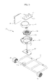
- the elevating device 40 includes an elevating motor 41 to generate a rotation force, a cam 42 that rotates upon receiving the rotation force of the elevating motor 41 through a shaft (41 a, FIG. 6 ) of the elevating motor 41, an elevating guide 44 to guide vertical movement of the brush 21 via interaction with the cam 42, and a rotation switch 43 to sense the height of the brush 21 while rotating along with the cam 42.
- the cam 42 is circumferentially provided at a lower surface thereof with a cam surface 42a.
- the cam surface 42a circumferentially extends and has a height that varies in multiple stages so as to vertically move the brush 21 in multiple stages in a stepwise manner.
- the multistage cam surface 42a circumferentially extends and the circumferentially extended portion increases in height in a stepwise manner, thereby acting to vertically move the height of the brush 21 stepwise via rotation of the cam 42. More particularly, in the present embodiment, the multistage cam surface 42a may sequentially raise the height of the brush 21 from the first stage to the fourth stage, and the stepwise height of the cam surface 42a may be repeated twice. In this way, whenever the cam 42 rotates once, the height of the brush 21 may vary twice in sequence from the first stage to the fourth stage.
- the rotation switch 43 includes a connecting shaft 43a connected to the cam 42 to rotate upon receiving rotation force from the cam 42, and a variable resistor 43b configured to rotate along with the connecting shaft 43a.
- the variable resistor 43b has a circular annular shape to endlessly rotate in a given direction, and has a resistance that varies stepwise in a circumferential direction.
- the variable resistor 43b rotates along with the connecting shaft 43a, and outputs voltage that varies stepwise based on a rotation angle thereof.
- variable resistor 43b rotates upon receiving rotation force from the cam 42 via the connecting shaft 43a of the rotation switch 43, output voltage of the variable resistor 43b varies stepwise based on rotation of the variable resistor 43b.
- a rotation angle of the cam 42 may be sensed based on the output voltage, and consequently the height of the brush 21 may be confirmed based on the rotation angle of the cam 42.
- the elevating motor 41 may be an Alternating Current (AC) motor that generates rotation force only in a given direction.
- AC Alternating Current
- the elevating motor 41 is fixedly mounted within the suction unit 20 via a fixing bracket 46.
- the elevating guide 44 has a rear end rotatably coupled to the bottom surface of the suction unit 20 and a front end, to which the above-described auxiliary wheels 45 are rotatably mounted at opposite sides.
- the elevating guide 44 is provided with a guide piece 44a to interact with the cam surface 42a formed at the lower surface of the cam 42.
- the guide piece 44a integrally extends upward from the center of the front end of the elevating guide 44, such that an upper end thereof is supported by the cam surface 42a.
- the elevating device 40 further includes a display unit 47 to allow the user to visually confirm the height of the brush 21, and a board assembly 48 to control operation of the elevating device 40 by measuring the output voltage of the rotation switch 43.
- the display unit 47 includes a plurality of light emitting diodes 47a, and a display substrate 47b on which the plurality of light emitting diodes 47a is placed.
- FIG. 5 is a view showing output voltages of the variable resistor 47b based on rotation angles of the variable resistor 43b when voltage of 5V is input to the variable resistor 43b of the rotation switch 43.
- the rotation switch 43 directly outputs the input voltage of 5V when the rotation angle is in a range of 300° ⁇ 0° in which the height of the brush 21 is at the first stage, outputs voltage of 2.4V when the rotation angle is in a range of 0° ⁇ 60° in which the height of the brush 21 is at the second stage, outputs voltage of 2.55V when the rotation angle is in a range of 60° ⁇ 100° in which the height of the brush 21 is at the third stage, and outputs voltage of 2.8V when the rotation angle is in a range of 100° ⁇ 140° in which the height of the brush 21 is at the fourth stage.
- the rotation switch 43 outputs voltage of 3.15V when the rotation angle is in a range of 140° ⁇ 180° in which the height of the brush 21 is at the first stage, outputs voltage of 3.55V when the rotation angle is in a range of 180° ⁇ 220° in which the height of the brush 21 is at the second stage, outputs voltage of 4.05V when the rotation angle is in a range of 220° ⁇ 260° in which the height of the brush 21 is at the third stage, and outputs voltage of 4.6V when the rotation angle is in a range of 260° ⁇ 300° in which the height of the brush 21 is at the fourth stage. In this way, it may be possible to confirm at which one of the first stage to the fourth stage the brush 21 is located via the output voltage of the rotation switch 43.
- the angle and input/output voltages are given by way of example, the angle may be changed based on the shape of the cam 42, and the voltage used may be changed based on a designer's need.
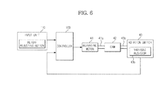
- the cleaning apparatus includes a controller 100 to control overall operation of the cleaning apparatus, and an input unit 110 including the above-described height adjusting button to allow the user to input a desired operation, among various operations.
- the above-described elevating motor 41 is controlled by the controller 100 to generate rotation force in a given direction so as to rotate the cam 42, the connecting shaft 43a, and the variable resistor 43b connected to the connecting shaft 43a.
- the controller 100 drives the elevating motor 41 to rotate the cam 42 in response to a height adjustment instruction input via the height adjusting button.
- the cam 42 acts to press the guide piece 44a of the elevating guide 44 downward via the cam surface 42a. Since the elevating guide 44 is supported on the floor via the auxiliary wheels 45 as described above, and therefore is not movable downward, the cam 42 is moved upward by reaction, as shown in FIG. 8 , and simultaneously the elevating motor 41 is moved upward along with the cam 42.
- the elevating motor 41 which is fixedly mounted, via the fixing bracket 46, within the suction unit 20 at the front end thereof, causes the front end of the suction unit 20 to rotate about the wheels 23 mounted to the rear end of the suction unit 20, and consequently the elevating guide 44 to rotate about the rear end thereof.
- the brush 21 mounted in the suction unit 20 at the front end thereof is also moved upward. That is, the height of the brush 21 varies.
- the connecting shaft 43a of the rotation switch 43 is connected to the cam 42, such that the variable resistor 43b rotates along with the cam 42 upon receiving rotation force transmitted through the connecting shaft 43a during rotation of the cam 42.
- output voltage of the variable resistor 43b varies stepwise to thereby be transmitted to the controller 100.
- the controller 100 drives the elevating motor 41 until the output voltage of the variable resistor 43b coincides with a preset voltage of the controller 100 corresponding to each height of the brush 21.
- the controller 100 stops driving of the elevating motor 41. In this way, the brush 21 is located at a height that the user selects via the height adjusting button.
- the elevating device 40 may vertically move the brush 21 placed at the front end of the suction unit 20 by allowing the suction unit 20 to rotate about the wheels 23 placed at the rear end thereof, but the disclosure is not limited thereto, and the brush 21 may be vertically moved in various ways.
- a cleaning apparatus may be structurally simple as a result of using an AC motor, which rotates in a given direction, as an elevating motor.
Landscapes
- Engineering & Computer Science (AREA)
- Mechanical Engineering (AREA)
- Nozzles For Electric Vacuum Cleaners (AREA)
- Electric Vacuum Cleaner (AREA)
Applications Claiming Priority (2)
| Application Number | Priority Date | Filing Date | Title |
|---|---|---|---|
| KR20110066164 | 2011-07-04 | ||
| KR1020120035958A KR20130004874A (ko) | 2011-07-04 | 2012-04-06 | 청소기 |
Publications (2)
| Publication Number | Publication Date |
|---|---|
| EP2543300A2 true EP2543300A2 (de) | 2013-01-09 |
| EP2543300A3 EP2543300A3 (de) | 2018-04-04 |
Family
ID=46506192
Family Applications (1)
| Application Number | Title | Priority Date | Filing Date |
|---|---|---|---|
| EP12174760.4A Withdrawn EP2543300A3 (de) | 2011-07-04 | 2012-07-03 | Reinigungsvorrichtung mit Höhenverstellbaren Bürsten |
Country Status (3)
| Country | Link |
|---|---|
| US (1) | US9138117B2 (de) |
| EP (1) | EP2543300A3 (de) |
| CN (1) | CN102860787B (de) |
Cited By (1)
| Publication number | Priority date | Publication date | Assignee | Title |
|---|---|---|---|---|
| CN113907659A (zh) * | 2021-11-05 | 2022-01-11 | 万可科技(深圳)有限公司 | 具有自清洁功能的洗地机 |
Families Citing this family (17)
| Publication number | Priority date | Publication date | Assignee | Title |
|---|---|---|---|---|
| WO2009117383A2 (en) | 2008-03-17 | 2009-09-24 | Electrolux Home Care Products, Inc. | Agitator with cleaning features |
| US9820626B2 (en) | 2008-03-17 | 2017-11-21 | Aktiebolaget Electrolux | Actuator mechanism for a brushroll cleaner |
| US9295362B2 (en) | 2008-03-17 | 2016-03-29 | Aktiebolaget Electrolux | Vacuum cleaner agitator cleaner with power control |
| US10117553B2 (en) | 2008-03-17 | 2018-11-06 | Aktiebolaget Electrolux | Cleaning nozzle for a vacuum cleaner |
| EP2770892B1 (de) | 2011-10-26 | 2015-09-23 | Aktiebolaget Electrolux | Reinigungsdüse für einen staubsauger |
| CN104080384B (zh) | 2012-02-02 | 2016-10-12 | 伊莱克斯公司 | 用于真空吸尘器吸嘴的清洁装置 |
| JP6272899B2 (ja) | 2012-12-21 | 2018-01-31 | アクティエボラゲット エレクトロラックス | 掃除機の回転可能部材のためのクリーニング装置、掃除機ノズル、掃除機、および掃除ユニット |
| US9072416B2 (en) * | 2013-03-15 | 2015-07-07 | Aktiebolaget Electrolux | Vacuum cleaner agitator cleaner with brushroll lifting mechanism |
| CN105392406B (zh) | 2013-05-02 | 2018-04-27 | 伊莱克斯公司 | 用于真空吸尘器的清洁吸嘴 |
| US20190133400A1 (en) * | 2016-05-11 | 2019-05-09 | Aktiebolaget Electrolux | Adjusting height of a robotic cleaning device |
| WO2019143700A1 (en) | 2018-01-17 | 2019-07-25 | Tti (Macao Commercial Offshore) Limited | System and method for operating a cleaning system based on a surface to be cleaned |
| CN110336512A (zh) * | 2019-07-08 | 2019-10-15 | 维沃移动通信有限公司 | 一种电机控制系统、方法和终端 |
| CN213850490U (zh) | 2019-07-29 | 2021-08-03 | 尚科宁家运营有限公司 | 机器人清洁器 |
| CN110479697B (zh) * | 2019-08-19 | 2021-10-19 | 河南宝合元汽车配件有限公司 | 一种废料清理设备 |
| CN116763195A (zh) * | 2022-03-07 | 2023-09-19 | 美智纵横科技有限责任公司 | 清洁装置的抹布机构及具有其的清洁装置 |
| CN117773441B (zh) * | 2024-02-26 | 2024-05-10 | 中国水利水电第九工程局有限公司 | 一种桥梁梁板加固焊接设备及焊接方法 |
| CN119036516B (zh) * | 2024-06-07 | 2025-07-25 | 华田智能机器人(南通)有限公司 | 一种自适应机器人 |
Family Cites Families (5)
| Publication number | Priority date | Publication date | Assignee | Title |
|---|---|---|---|---|
| JP2750976B2 (ja) * | 1992-03-19 | 1998-05-18 | シャープ株式会社 | 電気掃除機 |
| CN1611171A (zh) * | 2003-10-30 | 2005-05-04 | 乐金电子(天津)电器有限公司 | 自动吸尘器吸入刷头的控制装置及方法 |
| US7316051B2 (en) * | 2004-07-01 | 2008-01-08 | The Hoover Company | Suction nozzle height adjustment control circuit |
| US7293326B2 (en) * | 2004-07-29 | 2007-11-13 | Electrolux Home Care Products, Inc. | Vacuum cleaner alignment bracket |
| CN201673747U (zh) * | 2010-05-07 | 2010-12-15 | 孟阳 | 间角叠组电位器 |
-
2012
- 2012-07-02 US US13/539,893 patent/US9138117B2/en not_active Expired - Fee Related
- 2012-07-03 EP EP12174760.4A patent/EP2543300A3/de not_active Withdrawn
- 2012-07-04 CN CN201210231160.8A patent/CN102860787B/zh not_active Expired - Fee Related
Non-Patent Citations (1)
| Title |
|---|
| None |
Cited By (1)
| Publication number | Priority date | Publication date | Assignee | Title |
|---|---|---|---|---|
| CN113907659A (zh) * | 2021-11-05 | 2022-01-11 | 万可科技(深圳)有限公司 | 具有自清洁功能的洗地机 |
Also Published As
| Publication number | Publication date |
|---|---|
| US20130008469A1 (en) | 2013-01-10 |
| CN102860787A (zh) | 2013-01-09 |
| CN102860787B (zh) | 2016-08-03 |
| US9138117B2 (en) | 2015-09-22 |
| EP2543300A3 (de) | 2018-04-04 |
Similar Documents
| Publication | Publication Date | Title |
|---|---|---|
| US9138117B2 (en) | Cleaning apparatus | |
| US11737626B2 (en) | Cleaning robot and method for controlling the same | |
| US11464374B2 (en) | Robot cleaner | |
| US7316051B2 (en) | Suction nozzle height adjustment control circuit | |
| KR101758281B1 (ko) | 청소기 및 그 제어 방법 | |
| EP2989955B1 (de) | Reinigungsroboter und steuerungsverfahren dafür | |
| US10631701B2 (en) | Vacuum cleaner and handle thereof | |
| KR101562381B1 (ko) | 감지 핸들을 구비하는 로봇 진공 청소기 | |
| KR20190081047A (ko) | 로봇 청소기 | |
| CN1683120A (zh) | 带有机载操纵杆传感器的机器人设备和相关运行方法 | |
| EP3207850A1 (de) | Reiniger | |
| US20230389763A1 (en) | User-guided self-propelled cleaning device | |
| EP1707099B1 (de) | Stielstaubsauger mit Bewegungskontrollgriff | |
| CN114302662B (zh) | 具有搅拌器的清洁单元 | |
| KR20130004874A (ko) | 청소기 | |
| JP6857803B2 (ja) | 自走式掃除機 | |
| KR101985525B1 (ko) | 청소기 | |
| JP2021069446A (ja) | 電気掃除機 | |
| KR102021858B1 (ko) | 진공 청소기 | |
| KR102369187B1 (ko) | 진공 청소기 및 그의 제어방법 | |
| JP2018187024A (ja) | 電気器具 |
Legal Events
| Date | Code | Title | Description |
|---|---|---|---|
| PUAI | Public reference made under article 153(3) epc to a published international application that has entered the european phase |
Free format text: ORIGINAL CODE: 0009012 |
|
| AK | Designated contracting states |
Kind code of ref document: A2 Designated state(s): AL AT BE BG CH CY CZ DE DK EE ES FI FR GB GR HR HU IE IS IT LI LT LU LV MC MK MT NL NO PL PT RO RS SE SI SK SM TR |
|
| AX | Request for extension of the european patent |
Extension state: BA ME |
|
| PUAL | Search report despatched |
Free format text: ORIGINAL CODE: 0009013 |
|
| AK | Designated contracting states |
Kind code of ref document: A3 Designated state(s): AL AT BE BG CH CY CZ DE DK EE ES FI FR GB GR HR HU IE IS IT LI LT LU LV MC MK MT NL NO PL PT RO RS SE SI SK SM TR |
|
| AX | Request for extension of the european patent |
Extension state: BA ME |
|
| RIC1 | Information provided on ipc code assigned before grant |
Ipc: A47L 5/34 20060101ALI20180226BHEP Ipc: A47L 9/04 20060101AFI20180226BHEP |
|
| 17P | Request for examination filed |
Effective date: 20180629 |
|
| RBV | Designated contracting states (corrected) |
Designated state(s): AL AT BE BG CH CY CZ DE DK EE ES FI FR GB GR HR HU IE IS IT LI LT LU LV MC MK MT NL NO PL PT RO RS SE SI SK SM TR |
|
| STAA | Information on the status of an ep patent application or granted ep patent |
Free format text: STATUS: THE APPLICATION HAS BEEN WITHDRAWN |
|
| 18W | Application withdrawn |
Effective date: 20200430 |