EP2543301A1 - Aspirateur vertical - Google Patents
Aspirateur vertical Download PDFInfo
- Publication number
- EP2543301A1 EP2543301A1 EP12174930A EP12174930A EP2543301A1 EP 2543301 A1 EP2543301 A1 EP 2543301A1 EP 12174930 A EP12174930 A EP 12174930A EP 12174930 A EP12174930 A EP 12174930A EP 2543301 A1 EP2543301 A1 EP 2543301A1
- Authority
- EP
- European Patent Office
- Prior art keywords
- case
- dust removal
- upright cleaner
- removal unit
- cleaner according
- Prior art date
- Legal status (The legal status is an assumption and is not a legal conclusion. Google has not performed a legal analysis and makes no representation as to the accuracy of the status listed.)
- Granted
Links
Images





Classifications
-
- A—HUMAN NECESSITIES
- A47—FURNITURE; DOMESTIC ARTICLES OR APPLIANCES; COFFEE MILLS; SPICE MILLS; SUCTION CLEANERS IN GENERAL
- A47L—DOMESTIC WASHING OR CLEANING; SUCTION CLEANERS IN GENERAL
- A47L5/00—Structural features of suction cleaners
- A47L5/12—Structural features of suction cleaners with power-driven air-pumps or air-compressors, e.g. driven by motor vehicle engine vacuum
- A47L5/22—Structural features of suction cleaners with power-driven air-pumps or air-compressors, e.g. driven by motor vehicle engine vacuum with rotary fans
- A47L5/28—Suction cleaners with handles and nozzles fixed on the casings, e.g. wheeled suction cleaners with steering handle
- A47L5/30—Suction cleaners with handles and nozzles fixed on the casings, e.g. wheeled suction cleaners with steering handle with driven dust-loosening tools, e.g. rotating brushes
-
- A—HUMAN NECESSITIES
- A47—FURNITURE; DOMESTIC ARTICLES OR APPLIANCES; COFFEE MILLS; SPICE MILLS; SUCTION CLEANERS IN GENERAL
- A47L—DOMESTIC WASHING OR CLEANING; SUCTION CLEANERS IN GENERAL
- A47L9/00—Details or accessories of suction cleaners, e.g. mechanical means for controlling the suction or for effecting pulsating action; Storing devices specially adapted to suction cleaners or parts thereof; Carrying-vehicles specially adapted for suction cleaners
- A47L9/02—Nozzles
- A47L9/04—Nozzles with driven brushes or agitators
- A47L9/0461—Dust-loosening tools, e.g. agitators, brushes
- A47L9/0466—Rotating tools
- A47L9/0477—Rolls
-
- A—HUMAN NECESSITIES
- A47—FURNITURE; DOMESTIC ARTICLES OR APPLIANCES; COFFEE MILLS; SPICE MILLS; SUCTION CLEANERS IN GENERAL
- A47L—DOMESTIC WASHING OR CLEANING; SUCTION CLEANERS IN GENERAL
- A47L9/00—Details or accessories of suction cleaners, e.g. mechanical means for controlling the suction or for effecting pulsating action; Storing devices specially adapted to suction cleaners or parts thereof; Carrying-vehicles specially adapted for suction cleaners
- A47L9/02—Nozzles
- A47L9/04—Nozzles with driven brushes or agitators
-
- A—HUMAN NECESSITIES
- A47—FURNITURE; DOMESTIC ARTICLES OR APPLIANCES; COFFEE MILLS; SPICE MILLS; SUCTION CLEANERS IN GENERAL
- A47L—DOMESTIC WASHING OR CLEANING; SUCTION CLEANERS IN GENERAL
- A47L9/00—Details or accessories of suction cleaners, e.g. mechanical means for controlling the suction or for effecting pulsating action; Storing devices specially adapted to suction cleaners or parts thereof; Carrying-vehicles specially adapted for suction cleaners
- A47L9/02—Nozzles
- A47L9/04—Nozzles with driven brushes or agitators
- A47L9/0461—Dust-loosening tools, e.g. agitators, brushes
- A47L9/0483—Reciprocating or oscillating tools, e.g. vibrators, agitators, beaters
-
- A—HUMAN NECESSITIES
- A47—FURNITURE; DOMESTIC ARTICLES OR APPLIANCES; COFFEE MILLS; SPICE MILLS; SUCTION CLEANERS IN GENERAL
- A47L—DOMESTIC WASHING OR CLEANING; SUCTION CLEANERS IN GENERAL
- A47L9/00—Details or accessories of suction cleaners, e.g. mechanical means for controlling the suction or for effecting pulsating action; Storing devices specially adapted to suction cleaners or parts thereof; Carrying-vehicles specially adapted for suction cleaners
- A47L9/10—Filters; Dust separators; Dust removal; Automatic exchange of filters
- A47L9/16—Arrangement or disposition of cyclones or other devices with centrifugal action
- A47L9/1683—Dust collecting chambers; Dust collecting receptacles
-
- A—HUMAN NECESSITIES
- A47—FURNITURE; DOMESTIC ARTICLES OR APPLIANCES; COFFEE MILLS; SPICE MILLS; SUCTION CLEANERS IN GENERAL
- A47L—DOMESTIC WASHING OR CLEANING; SUCTION CLEANERS IN GENERAL
- A47L9/00—Details or accessories of suction cleaners, e.g. mechanical means for controlling the suction or for effecting pulsating action; Storing devices specially adapted to suction cleaners or parts thereof; Carrying-vehicles specially adapted for suction cleaners
- A47L9/20—Means for cleaning filters
-
- A—HUMAN NECESSITIES
- A47—FURNITURE; DOMESTIC ARTICLES OR APPLIANCES; COFFEE MILLS; SPICE MILLS; SUCTION CLEANERS IN GENERAL
- A47L—DOMESTIC WASHING OR CLEANING; SUCTION CLEANERS IN GENERAL
- A47L9/00—Details or accessories of suction cleaners, e.g. mechanical means for controlling the suction or for effecting pulsating action; Storing devices specially adapted to suction cleaners or parts thereof; Carrying-vehicles specially adapted for suction cleaners
- A47L9/10—Filters; Dust separators; Dust removal; Automatic exchange of filters
- A47L9/16—Arrangement or disposition of cyclones or other devices with centrifugal action
- A47L9/1658—Construction of outlets
- A47L9/1666—Construction of outlets with filtering means
Definitions
- Embodiments of the present invention relate to an upright cleaner configured to remove dust from a drum brush.
- a cleaner is an apparatus that removes foreign matter from a room to clean the room.
- a vacuum cleaner is generally used at home. The vacuum cleaner suctions air using suction force of a blowing device and separates foreign matter from the suctioned air using a filter to clean a room.
- the vacuum cleaner may be classified as a canister type vacuum cleaner or an upright vacuum cleaner.
- the canister type vacuum cleaner includes a main body having a blowing device and a dust collection device mounted therein, a suction body mounted separately from the main body to suction dust from a floor, and a connection hose connected between the main body and the suction body. To clean a room, therefore, a user may move the suction body in a cleaning direction while holding a handle mounted at the connection hose.
- the upright cleaner includes an upright main body and a suction body integrally coupled to the lower part of the main body.
- a user may move the entirety of the upright cleaner in a cleaning direction while holding a handle mounted at the upper side of the main body.
- a drum brush is mounted in the suction body of the upright cleaner to improve cleaning efficiency.
- the drum brush contacts a surface to be cleaned while being rotated at high speed to separate foreign matter from the surface.
- the separated foreign matter is suctioned into the suction body and is then introduced into a dust collection device provided in the main body.
- an upright cleaner includes a case having a suction port, a drum brush rotatably provided in the case to sweep and guide foreign matter to the suction port, a dust removal unit provided in the case so that the dust removal unit is moved between a first position where one side of the dust removal unit contacts the drum brush and a second position where the side of the dust removal unit is separated from the drum brush, and a lever connected to the dust removal unit to actuate the dust removal unit.
- the dust removal unit may include a bar-type body and a dusting part extending from the body so that the dusting part contacts the drum brush at the first position and is separated from the drum brush at the second position.
- the lever may include an extension part protruding above the case and a bent part extending from the end of the extension part so that the bent part is bent toward the front of the case, and the lever may be connected to the body.
- the upright cleaner may further include an elastic part provided between the bent part and the top of the case to elastically bias the bent part upward.
- one side of the lever may form an extension part protruding forward from the case, and the other side of the lever may be connected to the body.
- the extension part may be provided at the lower end thereof with a support part protruding forward from the case, and the upright cleaner may further include an elastic part provided between the support part and the extension part to elastically bias the extension part upward.
- the upright cleaner may further include an actuating unit coupled to the case to cover the extension part, the actuating unit being configured to be moved between an actuating position at which the extension part is pressed and a releasing position at which the extension part is released.
- the actuating unit may include a front plate provided at the front of the extension part and an upper plate connected to the upper end of the front plate and bent rearward.
- the upright cleaner may further include a locking unit hingedly coupled to the case above the upper plate, wherein the locking unit may lock the upper plate so that the actuating unit is held at the actuating position when the actuating unit is located at the actuating position.
- the actuating unit may include an elastic support part extending downward from a hinge shaft coupled to the case so that the rear of the elastic support is supported at the case, a catching part extending frontward from the hinge shaft so that the end of the catching part protrudes more forward than the end of the support part, and a footstool part extending frontward from the hinge shaft.
- the upper plate may be provided at one end thereof with an insertion groove formed by separation between the upper plate and the case, and the catching part may push the upper plate downward to hold the upper plate at the actuating position and may be received in the insertion groove at the releasing position.
- the upright cleaner may further include a pressing part provided at the inside of the front plate at a position corresponding to the extension part to press the extension part when the actuating unit is moved to the actuating position.
- the dusting part may include a brush.
- the dusting part may include one or more brush bundles arranged at intervals.
- an upright cleaner having a suction body, a main body and a handle, the upright cleaner, includes a case forming the external appearance of the suction body, a drum brush rotatably provided in the case, and a dust removal unit movably provided in the case, the dust removal unit performing an actuating operation through which dust is removed from the drum brush and a releasing operation through which dust is removed from the drum brush.
- the upright cleaner may further include a lever connected to the dust removal unit to control the dust removal unit to perform the actuating operation or the releasing operation.
- an upright cleaner includes a main body having a motor and a dust collection device, a handle extending from the main body, the handle having a manipulation part to drive the motor, a suction body having a suction port to suction air and a discharge port to supply the suctioned air to the main body, a drum brush provided in the suction body so that the drum brush is rotated by the motor to sweep and guide foreign matter to the suction port, and a dust removal unit provided in the suction body so that the dust removal unit is moved between a first position where the dust removal unit contacts the drum brush and a second position where the dust removal unit is separated from the drum brush.
- the dust removal unit may include a bar-type body and a dusting part extending from the body so that the dusting part contacts the drum brush at the first position and is separated from the drum brush at the second position.
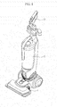
- FIG. 1 is a perspective view schematically showing the external appearance of an upright cleaner according to an embodiment of the present invention.
- the upright cleaner includes an upright main body 2, a suction body 1 mounted at the lower part of the front of the main body 2 to suction foreign matter from the floor in a room, and a handle 3 provided at the upper part of the main body 2 to allow a user to easily move the cleaner in a cleaning direction.
- a blowing device to generate suction force to suction foreign matter and a dust collection device to store the suctioned foreign matter are mounted in the main body 2.
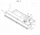
- FIG. 2 is a perspective view schematically showing a suction body of the upright cleaner according to the embodiment of the present invention.
- FIG. 3 is an exploded view showing components of the suction body of FIG. 2 .
- the suction body 1 a includes a case 10a forming the external appearance thereof, a suction port 60 provided at the lower part of the front of the case 10a to suction foreign matter from the floor in a room, a drum brush 50 rotatably provided at the lower end of the front of the case 10a in the case 10a to sweep and guide foreign matter to the suction port 60, a motor 501 to rotate the drum brush 50, a belt 502 to transmit drive force from the motor 501 to the drum brush 50, a dust removal unit 20 provided in the case 10a to remove hair or dust from the drum brush 50, and a lever 30a to rotate the dust removal unit 20.
- the drum brush 50 is formed in the shape of a long cylinder.
- the drum brush 50 is provided at the outer circumference thereof with a spiral brush extending outward.
- the brush sweeps foreign matter from the floor to introduce the foreign matter into the suction port 60. At this time, hair or dust is tangled on the brush.
- the case 10a includes a case body 112a, an upper case 111 a to cover the upper end of the case body 112a, and a lower case 113a, at which the suction port 60 is provided, to support the drum brush 50.
- the dust removal unit 20 includes a bar-type body 201, by which the dust removal unit 20 is supported at the case 10a, and a dusting part 202 extending from the body 201 to contact the drum brush 50.
- One side of the lever 30a includes an extension part 301 a protruding above the upper case 111a and a bent part 302a extending from the end of the extension part 301 a so that the bent part 302a is bent toward the front of the case 10a.
- the other side of the lever 30a is connected to the body 201 of the dust removal unit 20.
- the upright cleaner further includes an elastic part 40a provided between the upper case 111a and the bent part 302a of the lever 30a to elastically bias the bent part 302 upward.
- the elastic part 40a may include a spring.
- the elastic part 40a may include an elastic member to elastically bias the bent part 302 upward in addition to the spring.
- a downward protrusion 303a to hold the upper end of the elastic part 40a.
- the lower end of the elastic part 40a is supported at the upper case 111 a.
- FIG. 4A is a view showing an example of the dust removal unit of the upright cleaner according to the embodiment of the present invention.
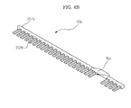
- FIG. 4B is a view showing another example of the dust removal unit of the upright cleaner according to the embodiment of the present invention.
- the dust removal unit 20 includes a bar-type body 201 and a dusting part 202 extending from the body 201.
- a dusting part 202a includes a brush formed over a body 201 a.
- the dust removal unit 20b of FIG. 4B includes a bar-type body 201 b and a dusting part 202b extending from the body 201 b, the dusting part 202b including one or more brush bundles arranged at intervals.
- the dust removal unit 20b is configured so that the dusting part 202b includes one or more brush bundles arranged at intervals.
- the dusting parts 202a and 202b of FIGS. 4A and 4B may be made of acrylonitrile butadiene styrene copolymer.
- the dusting parts 202a and 202b exhibit strength sufficient to sweep dust from the drum brush 50.
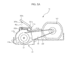
- FIGS. 5A and 5B are sectional views of the suction body 1a with the brush provided at the drum brush 50 being omitted.
- FIG. 5A is a view showing a state in which a dust removal unit according to an embodiment of the present invention is not operated.
- the bent part 302a of the lever is pushed upward by elastic force of the elastic part 40a provided at the upper part of the case 10a, and the entirety of the lever 30a, including the extension part 301a integrally formed at the bent part 302a, is rotated upward.
- the body 201 b of the dust removal unit 20b connected to the other side of the lever 30a is rotated with the result that the dusting part 202b extending from the body 201 b is also rotated and is thus separated from the drum brush 50.
- the drum brush 50 is operated without interference with the dusting part 202b.
- suction force is generated by the blowing device provided in the main body 2.
- the drum brush 50 is rotated, while contacting the floor in a room, to separate foreign matter from the floor.
- the separated foreign matter is suctioned into the suction port 60 provided at the lower part of the front of the case 10a of the suction body 1a together with air by the suction force generated by the blowing device.
- the suctioned air and the foreign matter contained in the air are introduced into the dust collection device (not shown) through a discharge port 70.
- the foreign matter is collected in the dust collection device, and the air is discharged from the suction body 1a.
- FIG. 5B is a view showing a state in which the dust removal unit according to the embodiment of the present invention is operated.
- the body 201 b of the dust removal unit 20b and the dusting part 202b extending from the body 201 b are rotated with the result that the dusting part 202b contacts the drum brush 50.
- the motor 501 and the drum brush 50 are rotated in the same manner as previously described.
- Air is suctioned into the suction port 60 by suction force generated by the blowing device, and the separated hair and dust are introduced into the dust collection device together with the air through the discharge port 70.
- the hair and dust are collected in the dust collection device, and the air is discharged from the suction body 1 a, in the same manner as previously described.
- the bent part 302a of the lever 30a When the user releases the bent part 302a of the lever 30a, the bent part 302a of the lever is pushed upward by elastic force of the elastic part 40a, as shown in FIG. 5A , and the entirety of the lever 30a, including the extension part 301a integrally formed at the bent part 302a, is rotated upward.
- the body 201 b of the dust removal unit 20b is rotated with the result that the dusting part 202b is separated from the drum brush 50 in the same manner as previously described.
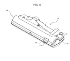
- FIG. 6 is a perspective view schematically showing the external appearance of a suction body of an upright cleaner according to another embodiment of the present invention.
- a suction body 1b is identical in construction to the previous embodiment in that the suction body 1b includes a case 10b, a suction port 60, a discharge port 70, a drum brush 50, a motor (not shown), a belt (not shown), a dust removal unit 20b and a lever 30b.
- the case 10b includes an upper case 111 b constituting the upper end of the case and a lower case 113b, at which the suction port 60 is provided, to support the drum brush 50.
- the dust removal unit 20b includes a bar-type body 201 b and a dusting part 202b including one or more brush bundles arranged at intervals, as previously described.
- One side of the lever 30b forms an extension part 301 b protruding forward from the upper case 111b, and the other side of the lever 30b is connected to a body 201 b of the dust removal unit 20b.
- a support part 41 b protruding forward from the upper case 111b.
- An elastic part 40b is provided between the extension part 301 b of the lever 30b and the support part 41 b of the upper case 111 b to elastically bias the extension part 301 b upward.
- the elastic part 40b may include a spring, as previously described. Also, the elastic part 40b may include an elastic member to elastically bias the extension part 301 b upward in addition to the spring.
- the lever 30b and the dust removal unit 20b are disposed at the front of the upper case 111b, and therefore, the upper end of the upper case 111 b may be formed in the shape of a semicircle.
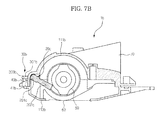
- FIGS. 7A and 7B are sectional views of the suction body 1b with the brush provided at the drum brush 50 being omitted.
- FIG. 7A is a view showing a state in which a dust removal unit according to another embodiment of the present invention is not operated.
- the extension part 301 b is pushed upward by elastic force of the elastic part 40b, and the entirety of the lever 30b is rotated upward.
- the body 201 b of the dust removal unit 20b connected to the other side of the lever 30b is rotated with the result that the dusting part 202b is separated from the drum brush 50.
- the upright cleaner is operated in the same manner as described with reference to FIG. 5A .
- FIG. 7B is a view showing a state in which the dust removal unit according to the embodiment of the present invention is operated.
- the body 201 b of the dust removal unit 20b Upon rotation of the lever 30b, the body 201 b of the dust removal unit 20b is also rotated with the result that and the dusting part 202b extending from the body 201 b contacts the drum brush 50.
- Air is suctioned into the suction port 60, and the separated hair and dust are introduced into the dust collection device together with the air through the discharge port 70 by suction force.
- the hair and dust are collected in the dust collection device, and the air is discharged from the suction body 1b.
- the extension part 301 b When the user releases the extension part 301 b, the extension part 301 b is pushed upward by elastic force of the elastic part 40b, as shown in FIG. 7A , and the entirety of the lever 30b is rotated upward.
- the dusting part 202b is separated from the drum brush 50 in the same manner as previously described.
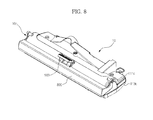
- FIG. 8 is a perspective view schematically showing the external appearance of a suction body of an upright cleaner according to yet another embodiment of the present invention.
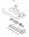
- FIG. 9 is an exploded view showing components of the suction body of the upright cleaner according to the embodiment of the present invention.
- a suction body 1c is identical in construction to the previous embodiment in that the suction body 1 c includes a case 10c, a suction port 60, a drum brush 50, a dust removal unit 20b and a lever 30c.
- Hair or dust is tangled on a brush provided at the outer circumference of the drum brush 50, as previously described.
- the case 10c includes an upper case 111 c constituting the upper end of the case and a lower case 113c, coupled to the lower end of the upper case 111c to support the drum brush 50, at which the suction port 60 is provided.
- the dust removal unit 20b includes a bar-type body 201 b and a dusting part 202b including one or more brush bundles extending from the body 201 b while being arranged at intervals, as previously described.
- One side of the lever 30c forms an extension part 301c protruding forward from the upper case 111c, and the other side of the lever 30c is connected to a body 201b of the dust removal unit 20b.
- a support part 41 c protruding forward from the upper case 111c.
- An elastic part 40c is provided between the extension part 301 c and the support part 41c of the upper case 111c to elastically bias the extension part 301c upward.
- an actuating unit 800 configured to cover the extension part 301 c.
- the actuating unit 800 includes a front plate, an upper plate and side plates.
- the front plate formed in the shape of a rectangle longer from side to side, is provided at the front of the extension part 301 c, the upper plate is connected to the upper end of the front plate and is bent rearward, and the side plates are coupled to the sides of the front plate and the upper plate.
- a pressing part 801 is coupled to the inside of the front plate at a position corresponding to the extension part 301c.
- connection part is provided at one side of each side plate of the actuating unit 800.
- the connection parts are hingedly coupled to the sides of the upper case 111c so that the actuating unit 800 is hingedly rotated upward and downward.
- a locking unit 900 is hingedly coupled to the upper case 111c above the upper plate.
- a footstool part 903 extends frontward from a hinge shaft of the locking unit 900, and an elastic support part 902 extending downward from the hinge shaft is connected to the footstool part 903.
- the rear of the elastic support part 902 contacts the upper case 111c to elastically bias the locking unit 900 in the forward direction.
- a pair of catching parts 901 extends downward from the hinge shaft so that the end of each catching part 901 protrudes more forward than the end of the elastic support part 902.
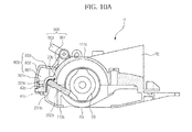
- FIGS. 10A and 10B the operation of a dust removal unit according to yet another embodiment of the present invention will be described with reference to FIGS. 10A and 10B .
- FIGS. 10A and 10B are sectional views of the suction body 1b with the brush provided at the drum brush 50 being omitted.
- FIG. 10A is a view showing a state in which a dust removal unit according to yet another embodiment of the present invention is operated.
- the pressing part 801 presses the extension part 301 c so that the extension part 301 c is rotated downward.
- the dust removal unit 20b Upon downward rotation of the extension part 301c, the dust removal unit 20b is rotated with the result that the dusting part 202b is located at a first position where the dusting part 202b contacts the drum brush 50.
- the separated hair and dust are introduced into the dust collection device together with air suctioned into the suction port 60 through the discharge port 70 by suction force.
- the hair and dust are collected in the dust collection device, and the air is discharged from the suction body 1c.
- the entirety of the locking unit 900 is rotated clockwise by elasticity of the elastic support part 902 (see FIG. 9 ).
- the catching parts 901 protrude forward, and the lower ends of the catching parts 901 push the top of the upper plate downward so that the actuating unit 800 is held at the actuating position.
- FIG. 10B is a view showing a state in which a dust removal unit according to yet another embodiment of the present invention is not operated.
- the locking unit 900 When a user pushes the footstool part 903 of the locking unit 900, the locking unit 900 is rotated counterclockwise against the elasticity of the elastic support part 902 (see FIG. 9 ).
- the protrusion degree of the catching parts 901 is reduced with the result that the ends of the catching parts 901 approach the upper case 111c, and one end of each of the catching parts 901 is received into a corresponding insertion groove 804.
- each of the catching parts 901 As one end of each of the catching parts 901 is inserted into the corresponding insertion groove 804, force pressing the upper plate downward is removed.
- the extension part 301 c is pushed upward by elasticity of the elastic part 40c, and the entirety of the lever 30c is rotated upward.
- the extension part 301c pushes the pressing part 801 upward, and the entirety of the actuating unit 800 is rotated upward.
- the dust removal unit 20b Upon rotation of the lever 30c, the dust removal unit 20b is moved to a second position where the dusting part 202b is separated from the drum brush, as previously described.
- a normal cleaning operation is performed without removal of dust from the drum brush.
Landscapes
- Engineering & Computer Science (AREA)
- Mechanical Engineering (AREA)
- Nozzles For Electric Vacuum Cleaners (AREA)
Priority Applications (2)
| Application Number | Priority Date | Filing Date | Title |
|---|---|---|---|
| EP17172688.8A EP3231343B1 (fr) | 2011-07-05 | 2012-07-04 | Aspirateur vertical |
| EP17172811.6A EP3231344B1 (fr) | 2011-07-05 | 2012-07-04 | Corps d'aspiration pour un aspirateur vertical |
Applications Claiming Priority (1)
| Application Number | Priority Date | Filing Date | Title |
|---|---|---|---|
| KR1020110066535A KR20130005135A (ko) | 2011-07-05 | 2011-07-05 | 업라이트 청소기 |
Related Child Applications (4)
| Application Number | Title | Priority Date | Filing Date |
|---|---|---|---|
| EP17172688.8A Division EP3231343B1 (fr) | 2011-07-05 | 2012-07-04 | Aspirateur vertical |
| EP17172688.8A Division-Into EP3231343B1 (fr) | 2011-07-05 | 2012-07-04 | Aspirateur vertical |
| EP17172811.6A Division EP3231344B1 (fr) | 2011-07-05 | 2012-07-04 | Corps d'aspiration pour un aspirateur vertical |
| EP17172811.6A Division-Into EP3231344B1 (fr) | 2011-07-05 | 2012-07-04 | Corps d'aspiration pour un aspirateur vertical |
Publications (2)
| Publication Number | Publication Date |
|---|---|
| EP2543301A1 true EP2543301A1 (fr) | 2013-01-09 |
| EP2543301B1 EP2543301B1 (fr) | 2017-08-30 |
Family
ID=46651361
Family Applications (3)
| Application Number | Title | Priority Date | Filing Date |
|---|---|---|---|
| EP17172811.6A Active EP3231344B1 (fr) | 2011-07-05 | 2012-07-04 | Corps d'aspiration pour un aspirateur vertical |
| EP17172688.8A Active EP3231343B1 (fr) | 2011-07-05 | 2012-07-04 | Aspirateur vertical |
| EP12174930.3A Active EP2543301B1 (fr) | 2011-07-05 | 2012-07-04 | Aspirateur vertical |
Family Applications Before (2)
| Application Number | Title | Priority Date | Filing Date |
|---|---|---|---|
| EP17172811.6A Active EP3231344B1 (fr) | 2011-07-05 | 2012-07-04 | Corps d'aspiration pour un aspirateur vertical |
| EP17172688.8A Active EP3231343B1 (fr) | 2011-07-05 | 2012-07-04 | Aspirateur vertical |
Country Status (3)
| Country | Link |
|---|---|
| US (3) | US9144356B2 (fr) |
| EP (3) | EP3231344B1 (fr) |
| KR (1) | KR20130005135A (fr) |
Cited By (32)
| Publication number | Priority date | Publication date | Assignee | Title |
|---|---|---|---|---|
| WO2014177171A1 (fr) * | 2013-04-29 | 2014-11-06 | Aktiebolaget Electrolux | Buse destinée à un aspirateur et aspirateur |
| WO2014177216A1 (fr) * | 2013-05-02 | 2014-11-06 | Aktiebolaget Electrolux | Buse de nettoyage pour un aspirateur |
| WO2014140872A3 (fr) * | 2013-03-15 | 2015-01-08 | Aktiebolaget Electrolux | Nettoyeur d'agitateur pour aspirateur à mécanisme de levage de cylindre-brosseur |
| CN104905733A (zh) * | 2015-07-07 | 2015-09-16 | 浙江工业大学 | 一种适用于纺织物的吸尘头 |
| US9192273B2 (en) | 2008-03-17 | 2015-11-24 | Aktiebolaget Electrolux | Brushroll cleaning feature with overload protection during cleaning |
| US9295362B2 (en) | 2008-03-17 | 2016-03-29 | Aktiebolaget Electrolux | Vacuum cleaner agitator cleaner with power control |
| US9314140B2 (en) | 2011-10-26 | 2016-04-19 | Aktiebolaget Electrolux | Cleaning nozzle for a vacuum cleaner |
| US9820626B2 (en) | 2008-03-17 | 2017-11-21 | Aktiebolaget Electrolux | Actuator mechanism for a brushroll cleaner |
| US9993847B2 (en) | 2012-02-02 | 2018-06-12 | Aktiebolaget Electrolux | Cleaning arrangement for a nozzle of a vacuum cleaner |
| US10045672B2 (en) | 2012-12-21 | 2018-08-14 | Aktiebolaget Electrolux | Cleaning arrangement for a rotatable member of a vacuum cleaner, cleaner nozzle, vacuum cleaner and cleaning unit |
| US10117553B2 (en) | 2008-03-17 | 2018-11-06 | Aktiebolaget Electrolux | Cleaning nozzle for a vacuum cleaner |
| USD837470S1 (en) | 2016-03-28 | 2019-01-01 | Sharkninja Operating Llc | Surface cleaning head with leading roller |
| USD849345S1 (en) | 2016-10-21 | 2019-05-21 | Sharkninja Operating Llc | Roller cleaning unit |
| USD853063S1 (en) | 2017-05-25 | 2019-07-02 | Sharkninja Operating Llc | Surface cleaning head with dual rollers |
| WO2019133497A1 (fr) | 2017-12-27 | 2019-07-04 | Sharkninja Operating Llc | Appareil de nettoyage avec unité de peignage sélectionnable permettant de retirer des débris d'un rouleau de nettoyage |
| WO2020033848A1 (fr) | 2018-08-10 | 2020-02-13 | Sharkninja Operating Llc | Système et procédé de réduction du bruit et/ou des vibrations dans un appareil de nettoyage doté d'une unité de peignage pour éliminer des débris |
| US10702108B2 (en) | 2015-09-28 | 2020-07-07 | Sharkninja Operating Llc | Surface cleaning head for vacuum cleaner |
| US10898042B2 (en) | 2017-08-16 | 2021-01-26 | Sharkninja Operating Llc | Robotic vacuum |
| US10925448B2 (en) | 2015-10-21 | 2021-02-23 | Sharkninja Operating Llc | Surface cleaning head with leading roller |
| US10925447B2 (en) | 2017-03-10 | 2021-02-23 | Sharkninja Operating Llc | Agitator with debrider and hair removal |
| US11202542B2 (en) | 2017-05-25 | 2021-12-21 | Sharkninja Operating Llc | Robotic cleaner with dual cleaning rollers |
| EP3932278A1 (fr) * | 2020-06-10 | 2022-01-05 | BSH Hausgeräte GmbH | Brosse à plancher et aspirateur |
| USD944475S1 (en) | 2018-11-08 | 2022-02-22 | Sharkninja Operating Llc | Hand vacuum cleaner |
| GB2568012B (en) * | 2016-09-09 | 2022-08-10 | Sharkninja Operating Llc | Agitator with hair removal |
| US11458771B2 (en) | 2017-08-31 | 2022-10-04 | Sharkninja Operating Llc | Wheels having shock absorbing characteristics and a surface treatment apparatus using the same |
| US11633764B2 (en) | 2017-12-27 | 2023-04-25 | Sharkninja Operating Llc | Cleaning apparatus with anti-hair wrap management systems |
| US11647881B2 (en) | 2015-10-21 | 2023-05-16 | Sharkninja Operating Llc | Cleaning apparatus with combing unit for removing debris from cleaning roller |
| US11672393B2 (en) | 2017-12-27 | 2023-06-13 | Sharkninja Operating Llc | Cleaning apparatus with selectable combing unit for removing debris from cleaning roller |
| US11707171B2 (en) | 2017-05-26 | 2023-07-25 | Sharkninja Operating Llc | Hair cutting brushroll |
| US11759069B2 (en) | 2018-10-19 | 2023-09-19 | Sharkninja Operating Llc | Agitator for a surface treatment apparatus and a surface treatment apparatus having the same |
| US11992172B2 (en) | 2018-10-19 | 2024-05-28 | Sharkninja Operating Llc | Agitator for a surface treatment apparatus and a surface treatment apparatus having the same |
| EP4321078A4 (fr) * | 2021-04-06 | 2024-10-02 | Jiangsu Midea Cleaning Appliances Co., Ltd. | Appareil de commande pour auto-nettoyage de laveur de sol et laveur de sol |
Families Citing this family (20)
| Publication number | Priority date | Publication date | Assignee | Title |
|---|---|---|---|---|
| USD673155S1 (en) * | 2011-06-16 | 2012-12-25 | Pfu Limited | Scanner |
| KR20130005135A (ko) * | 2011-07-05 | 2013-01-15 | 삼성전자주식회사 | 업라이트 청소기 |
| USD684326S1 (en) * | 2011-10-28 | 2013-06-11 | Panasonic Corporation | Vacuum cleaner |
| USD693073S1 (en) * | 2012-01-13 | 2013-11-05 | Samsung Electronics Co., Ltd. | Vacuum cleaner |
| GB201404917D0 (en) * | 2014-03-19 | 2014-04-30 | Dyson Technology Ltd | Cleaner head |
| KR102452480B1 (ko) * | 2015-09-02 | 2022-10-11 | 삼성전자주식회사 | 진공 청소기 |
| CN118452738A (zh) * | 2015-10-26 | 2024-08-09 | 范颂尼控股有限公司 | 真空吸尘器头 |
| WO2018074848A1 (fr) * | 2016-10-19 | 2018-04-26 | Samsung Electronics Co., Ltd. | Aspirateur robot |
| USD868400S1 (en) | 2017-07-25 | 2019-11-26 | Sharkninja Operating Llc | Hand vacuum component |
| USD874757S1 (en) | 2017-07-25 | 2020-02-04 | Sharkninja Operating Llc | Handheld vacuum component |
| KR102369190B1 (ko) * | 2020-07-23 | 2022-03-02 | 엘지전자 주식회사 | 노즐부, 이를 포함하는 로봇 청소기 및 그 제어 방법 |
| USD1033773S1 (en) * | 2021-05-13 | 2024-07-02 | Jiangsu Midea Cleaning Appliances Co., Ltd. | Floor cleaning machine |
| USD1019031S1 (en) * | 2021-05-17 | 2024-03-19 | Jiangsu Midea Cleaning Appliances Co., Ltd. | Floor cleaning machine |
| USD1024464S1 (en) * | 2021-06-08 | 2024-04-23 | Sharkninja (China) Technology Company Limited | Floor scrubber |
| USD1020148S1 (en) * | 2021-08-07 | 2024-03-26 | Yongkang Baisuikang Technology Co., Ltd. | Cleaning machine |
| USD1033768S1 (en) * | 2021-08-10 | 2024-07-02 | Kingclean Electric Co., Ltd. | Floor scrubber |
| USD1047326S1 (en) * | 2022-07-20 | 2024-10-15 | Bissell Inc. | Vacuum cleaner |
| WO2024064786A1 (fr) | 2022-09-23 | 2024-03-28 | Techtronic Cordless Gp | Nervure économiseur de cordon |
| USD1123276S1 (en) * | 2023-10-25 | 2026-04-21 | Jiangsu Midea Cleaning Appliances Co., Ltd. | Upright vacuum cleaner |
| USD1105665S1 (en) * | 2023-10-26 | 2025-12-09 | Jiangsu Midea Cleaning Appliances Co., Ltd. | Upright vacuum cleaner |
Citations (5)
| Publication number | Priority date | Publication date | Assignee | Title |
|---|---|---|---|---|
| JPH05103740A (ja) * | 1991-10-15 | 1993-04-27 | Akai Electric Co Ltd | 電気掃除機の吸込口体 |
| JPH05305044A (ja) * | 1992-05-07 | 1993-11-19 | Sanyo Electric Co Ltd | 電気掃除機の吸込具 |
| US20030204923A1 (en) * | 2002-05-02 | 2003-11-06 | Kazuo Nakamura | Cleaning implement |
| US20090229075A1 (en) * | 2008-03-17 | 2009-09-17 | Electrolux Home Care Products, Inc. | Agitator with Cleaning Features |
| GB2469729A (en) * | 2009-04-23 | 2010-10-27 | Samsung Kwangju Electronics Co | Nozzle assembly |
Family Cites Families (8)
| Publication number | Priority date | Publication date | Assignee | Title |
|---|---|---|---|---|
| US2960714A (en) * | 1958-12-04 | 1960-11-22 | Electrolux Corp | Combination carpet sweeper and vacuum cleaner |
| JPS513740A (ja) | 1974-06-28 | 1976-01-13 | Tokyo Shibaura Electric Co | Nyushutsuryokuseigyosochi |
| JPH03292920A (ja) | 1990-04-10 | 1991-12-24 | Yoshihei Hattori | 掃除機用吸入ノズル |
| KR100466320B1 (ko) * | 2002-09-10 | 2005-01-14 | 삼성광주전자 주식회사 | 진공청소기용 회전 브러시 |
| JP2006334084A (ja) | 2005-06-01 | 2006-12-14 | Toshiba Tec Corp | 電気掃除機用吸込口体 |
| JP4801516B2 (ja) | 2006-06-23 | 2011-10-26 | 日立アプライアンス株式会社 | 電気掃除機の吸口体及びこの吸口体を用いた電気掃除機 |
| JP2006312066A (ja) | 2006-07-11 | 2006-11-16 | Mitsubishi Electric Corp | 電気掃除機 |
| KR20130005135A (ko) * | 2011-07-05 | 2013-01-15 | 삼성전자주식회사 | 업라이트 청소기 |
-
2011
- 2011-07-05 KR KR1020110066535A patent/KR20130005135A/ko not_active Ceased
-
2012
- 2012-06-29 US US13/537,928 patent/US9144356B2/en active Active
- 2012-07-04 EP EP17172811.6A patent/EP3231344B1/fr active Active
- 2012-07-04 EP EP17172688.8A patent/EP3231343B1/fr active Active
- 2012-07-04 EP EP12174930.3A patent/EP2543301B1/fr active Active
-
2015
- 2015-08-27 US US14/837,629 patent/US10130225B2/en active Active
-
2018
- 2018-08-29 US US16/116,258 patent/US10542857B2/en active Active
Patent Citations (5)
| Publication number | Priority date | Publication date | Assignee | Title |
|---|---|---|---|---|
| JPH05103740A (ja) * | 1991-10-15 | 1993-04-27 | Akai Electric Co Ltd | 電気掃除機の吸込口体 |
| JPH05305044A (ja) * | 1992-05-07 | 1993-11-19 | Sanyo Electric Co Ltd | 電気掃除機の吸込具 |
| US20030204923A1 (en) * | 2002-05-02 | 2003-11-06 | Kazuo Nakamura | Cleaning implement |
| US20090229075A1 (en) * | 2008-03-17 | 2009-09-17 | Electrolux Home Care Products, Inc. | Agitator with Cleaning Features |
| GB2469729A (en) * | 2009-04-23 | 2010-10-27 | Samsung Kwangju Electronics Co | Nozzle assembly |
Cited By (63)
| Publication number | Priority date | Publication date | Assignee | Title |
|---|---|---|---|---|
| US10117553B2 (en) | 2008-03-17 | 2018-11-06 | Aktiebolaget Electrolux | Cleaning nozzle for a vacuum cleaner |
| US9295364B2 (en) | 2008-03-17 | 2016-03-29 | Aktiebolaget Electrolux | Brushroll cleaning feature with spaced brushes and friction surfaces to prevent contact |
| US9820624B2 (en) | 2008-03-17 | 2017-11-21 | Aktiebolaget Electrolux | Vacuum cleaner brushroll cleaner configuration |
| US9820626B2 (en) | 2008-03-17 | 2017-11-21 | Aktiebolaget Electrolux | Actuator mechanism for a brushroll cleaner |
| US9375122B2 (en) | 2008-03-17 | 2016-06-28 | Aktiebolaget Electrolux | Automated brushroll cleaning |
| US9192273B2 (en) | 2008-03-17 | 2015-11-24 | Aktiebolaget Electrolux | Brushroll cleaning feature with overload protection during cleaning |
| US9295362B2 (en) | 2008-03-17 | 2016-03-29 | Aktiebolaget Electrolux | Vacuum cleaner agitator cleaner with power control |
| US9839335B2 (en) | 2011-10-26 | 2017-12-12 | Aktiebolaget Electrolux | Cleaning nozzle for a vacuum cleaner |
| US9314140B2 (en) | 2011-10-26 | 2016-04-19 | Aktiebolaget Electrolux | Cleaning nozzle for a vacuum cleaner |
| US10376114B2 (en) | 2011-10-26 | 2019-08-13 | Aktiebolaget Electrolux | Cleaning nozzle for a vacuum cleaner |
| US9833115B2 (en) | 2011-10-26 | 2017-12-05 | Aktiebolaget Electrolux | Cleaning nozzle for a vacuum cleaner |
| US9993847B2 (en) | 2012-02-02 | 2018-06-12 | Aktiebolaget Electrolux | Cleaning arrangement for a nozzle of a vacuum cleaner |
| US10045672B2 (en) | 2012-12-21 | 2018-08-14 | Aktiebolaget Electrolux | Cleaning arrangement for a rotatable member of a vacuum cleaner, cleaner nozzle, vacuum cleaner and cleaning unit |
| WO2014140872A3 (fr) * | 2013-03-15 | 2015-01-08 | Aktiebolaget Electrolux | Nettoyeur d'agitateur pour aspirateur à mécanisme de levage de cylindre-brosseur |
| US9072416B2 (en) | 2013-03-15 | 2015-07-07 | Aktiebolaget Electrolux | Vacuum cleaner agitator cleaner with brushroll lifting mechanism |
| WO2014177171A1 (fr) * | 2013-04-29 | 2014-11-06 | Aktiebolaget Electrolux | Buse destinée à un aspirateur et aspirateur |
| US9775477B2 (en) | 2013-05-02 | 2017-10-03 | Aktiebolaget Electrolux | Cleaning nozzle for a vacuum cleaner |
| EP3289946A1 (fr) * | 2013-05-02 | 2018-03-07 | Aktiebolaget Electrolux | Buse de nettoyage pour aspirateur |
| WO2014177216A1 (fr) * | 2013-05-02 | 2014-11-06 | Aktiebolaget Electrolux | Buse de nettoyage pour un aspirateur |
| CN105392406A (zh) * | 2013-05-02 | 2016-03-09 | 伊莱克斯公司 | 用于真空吸尘器的清洁吸嘴 |
| CN104905733B (zh) * | 2015-07-07 | 2018-04-27 | 浙江工业大学 | 一种适用于纺织物的吸尘头 |
| CN104905733A (zh) * | 2015-07-07 | 2015-09-16 | 浙江工业大学 | 一种适用于纺织物的吸尘头 |
| US12070177B2 (en) | 2015-09-28 | 2024-08-27 | Sharkninja Operating Llc | Surface cleaning head for vacuum cleaner |
| US10702108B2 (en) | 2015-09-28 | 2020-07-07 | Sharkninja Operating Llc | Surface cleaning head for vacuum cleaner |
| US12048410B2 (en) | 2015-10-21 | 2024-07-30 | Sharkninja Operating Llc | Surface cleaning head with dual rotating agitators |
| US11712139B2 (en) | 2015-10-21 | 2023-08-01 | Sharkninja Operating Llc | Surface cleaning head with leading roller |
| US10925448B2 (en) | 2015-10-21 | 2021-02-23 | Sharkninja Operating Llc | Surface cleaning head with leading roller |
| US11278171B2 (en) | 2015-10-21 | 2022-03-22 | Sharkninja Operating Llc | Surface cleaning head with dual rotating agitators |
| US11647881B2 (en) | 2015-10-21 | 2023-05-16 | Sharkninja Operating Llc | Cleaning apparatus with combing unit for removing debris from cleaning roller |
| US12390064B2 (en) | 2015-10-21 | 2025-08-19 | Sharkninja Operating Llc | Cleaning apparatus with combing unit for removing debris from cleaning roller |
| USD837470S1 (en) | 2016-03-28 | 2019-01-01 | Sharkninja Operating Llc | Surface cleaning head with leading roller |
| USD855269S1 (en) | 2016-03-28 | 2019-07-30 | Sharkninja Operating Llc | Surface cleaning head component of a vacuum cleaner |
| USD929055S1 (en) | 2016-03-28 | 2021-08-24 | Sharkninja Operating Llc | Surface cleaning head with leading roller |
| USD846821S1 (en) | 2016-03-28 | 2019-04-23 | Sharkninja Operating Llc | Surface cleaning head component of a vacuum cleaner |
| US12453451B2 (en) | 2016-09-09 | 2025-10-28 | Sharkninja Operating Llc | Agitator with hair removal |
| GB2568012B (en) * | 2016-09-09 | 2022-08-10 | Sharkninja Operating Llc | Agitator with hair removal |
| US12310547B2 (en) | 2016-09-09 | 2025-05-27 | Sharkninja Operating Llc | Agitator with hair removal |
| USD872955S1 (en) | 2016-10-21 | 2020-01-14 | Sharkninja Operating Llc | Surface cleaning head |
| USD849345S1 (en) | 2016-10-21 | 2019-05-21 | Sharkninja Operating Llc | Roller cleaning unit |
| US12376720B2 (en) | 2017-03-10 | 2025-08-05 | Sharkninja Operating Llc | Agitator with debrider and hair removal |
| US10925447B2 (en) | 2017-03-10 | 2021-02-23 | Sharkninja Operating Llc | Agitator with debrider and hair removal |
| US11925303B2 (en) | 2017-03-10 | 2024-03-12 | Sharkninja Operating Llc | Agitator with debrider and hair removal |
| USD853063S1 (en) | 2017-05-25 | 2019-07-02 | Sharkninja Operating Llc | Surface cleaning head with dual rollers |
| US11202542B2 (en) | 2017-05-25 | 2021-12-21 | Sharkninja Operating Llc | Robotic cleaner with dual cleaning rollers |
| USD925848S1 (en) | 2017-05-25 | 2021-07-20 | Sharkninja Operating Llc | Surface cleaning head |
| US11839346B2 (en) | 2017-05-25 | 2023-12-12 | Sharkninja Operating Llc | Robotic cleaner with dual cleaning rollers |
| US12342979B2 (en) | 2017-05-25 | 2025-07-01 | Sharkninja Operating Llc | Robotic cleaner with dual cleaning rollers |
| US11707171B2 (en) | 2017-05-26 | 2023-07-25 | Sharkninja Operating Llc | Hair cutting brushroll |
| US10898042B2 (en) | 2017-08-16 | 2021-01-26 | Sharkninja Operating Llc | Robotic vacuum |
| US11458771B2 (en) | 2017-08-31 | 2022-10-04 | Sharkninja Operating Llc | Wheels having shock absorbing characteristics and a surface treatment apparatus using the same |
| EP3731714A4 (fr) * | 2017-12-27 | 2020-12-23 | SharkNinja Operating LLC | Appareil de nettoyage avec unité de peignage sélectionnable permettant de retirer des débris d'un rouleau de nettoyage |
| US11633764B2 (en) | 2017-12-27 | 2023-04-25 | Sharkninja Operating Llc | Cleaning apparatus with anti-hair wrap management systems |
| CN111936020B (zh) * | 2017-12-27 | 2022-07-12 | 尚科宁家运营有限公司 | 具有用于从清洁辊移除碎屑的可选梳理单元的清洁设备 |
| US11672393B2 (en) | 2017-12-27 | 2023-06-13 | Sharkninja Operating Llc | Cleaning apparatus with selectable combing unit for removing debris from cleaning roller |
| CN111936020A (zh) * | 2017-12-27 | 2020-11-13 | 尚科宁家运营有限公司 | 具有用于从清洁辊移除碎屑的可选梳理单元的清洁设备 |
| WO2019133497A1 (fr) | 2017-12-27 | 2019-07-04 | Sharkninja Operating Llc | Appareil de nettoyage avec unité de peignage sélectionnable permettant de retirer des débris d'un rouleau de nettoyage |
| EP3833220A4 (fr) * | 2018-08-10 | 2022-06-08 | SharkNinja Operating LLC | Système et procédé de réduction du bruit et/ou des vibrations dans un appareil de nettoyage doté d'une unité de peignage pour éliminer des débris |
| WO2020033848A1 (fr) | 2018-08-10 | 2020-02-13 | Sharkninja Operating Llc | Système et procédé de réduction du bruit et/ou des vibrations dans un appareil de nettoyage doté d'une unité de peignage pour éliminer des débris |
| US11759069B2 (en) | 2018-10-19 | 2023-09-19 | Sharkninja Operating Llc | Agitator for a surface treatment apparatus and a surface treatment apparatus having the same |
| US11992172B2 (en) | 2018-10-19 | 2024-05-28 | Sharkninja Operating Llc | Agitator for a surface treatment apparatus and a surface treatment apparatus having the same |
| USD944475S1 (en) | 2018-11-08 | 2022-02-22 | Sharkninja Operating Llc | Hand vacuum cleaner |
| EP3932278A1 (fr) * | 2020-06-10 | 2022-01-05 | BSH Hausgeräte GmbH | Brosse à plancher et aspirateur |
| EP4321078A4 (fr) * | 2021-04-06 | 2024-10-02 | Jiangsu Midea Cleaning Appliances Co., Ltd. | Appareil de commande pour auto-nettoyage de laveur de sol et laveur de sol |
Also Published As
| Publication number | Publication date |
|---|---|
| US10542857B2 (en) | 2020-01-28 |
| US20180368633A1 (en) | 2018-12-27 |
| EP3231343B1 (fr) | 2021-04-07 |
| EP3231344A1 (fr) | 2017-10-18 |
| US10130225B2 (en) | 2018-11-20 |
| KR20130005135A (ko) | 2013-01-15 |
| EP2543301B1 (fr) | 2017-08-30 |
| US20130007982A1 (en) | 2013-01-10 |
| US20150359396A1 (en) | 2015-12-17 |
| EP3231344B1 (fr) | 2020-06-24 |
| EP3231343A1 (fr) | 2017-10-18 |
| US9144356B2 (en) | 2015-09-29 |
Similar Documents
| Publication | Publication Date | Title |
|---|---|---|
| EP2543301B1 (fr) | Aspirateur vertical | |
| KR102452480B1 (ko) | 진공 청소기 | |
| KR102466282B1 (ko) | 청소기 | |
| EP2181634B1 (fr) | Unité de buse d'aspirateur | |
| US7594296B2 (en) | Convertible vacuum cleaner | |
| CN105078366B (zh) | 真空清洁器 | |
| CN204445685U (zh) | 电动吸尘器 | |
| US11457784B2 (en) | Vacuum cleaner with dust bag | |
| US20070209149A1 (en) | Vacuum cleaner | |
| US20170347850A1 (en) | Vacuum cleaner | |
| KR102228892B1 (ko) | 진공청소기 | |
| KR100968335B1 (ko) | 청소기 | |
| JP2009504311A (ja) | 真空掃除機 | |
| KR101208556B1 (ko) | 업라이트형 진공 청소기 | |
| KR102037074B1 (ko) | 진공청소기 | |
| CN116528738A (zh) | 清洁设备 | |
| JP7035446B2 (ja) | 吸込具及び電気掃除機 | |
| JP4713958B2 (ja) | 電気掃除機 | |
| JP5272766B2 (ja) | 電気掃除機 | |
| TWI801880B (zh) | 吸塵器 | |
| JP3684864B2 (ja) | スティック型掃除機 | |
| JP2023147417A (ja) | 電気掃除機 | |
| KR20110047597A (ko) | 진공청소기 | |
| JP2017018413A (ja) | 電気掃除機 | |
| KR20120045990A (ko) | 업라이트 형 진공청소기 |
Legal Events
| Date | Code | Title | Description |
|---|---|---|---|
| PUAI | Public reference made under article 153(3) epc to a published international application that has entered the european phase |
Free format text: ORIGINAL CODE: 0009012 |
|
| AK | Designated contracting states |
Kind code of ref document: A1 Designated state(s): AL AT BE BG CH CY CZ DE DK EE ES FI FR GB GR HR HU IE IS IT LI LT LU LV MC MK MT NL NO PL PT RO RS SE SI SK SM TR |
|
| AX | Request for extension of the european patent |
Extension state: BA ME |
|
| 17P | Request for examination filed |
Effective date: 20130709 |
|
| RBV | Designated contracting states (corrected) |
Designated state(s): AL AT BE BG CH CY CZ DE DK EE ES FI FR GB GR HR HU IE IS IT LI LT LU LV MC MK MT NL NO PL PT RO RS SE SI SK SM TR |
|
| 17Q | First examination report despatched |
Effective date: 20140218 |
|
| GRAP | Despatch of communication of intention to grant a patent |
Free format text: ORIGINAL CODE: EPIDOSNIGR1 |
|
| STAA | Information on the status of an ep patent application or granted ep patent |
Free format text: STATUS: GRANT OF PATENT IS INTENDED |
|
| INTG | Intention to grant announced |
Effective date: 20170119 |
|
| GRAS | Grant fee paid |
Free format text: ORIGINAL CODE: EPIDOSNIGR3 |
|
| GRAA | (expected) grant |
Free format text: ORIGINAL CODE: 0009210 |
|
| STAA | Information on the status of an ep patent application or granted ep patent |
Free format text: STATUS: THE PATENT HAS BEEN GRANTED |
|
| AK | Designated contracting states |
Kind code of ref document: B1 Designated state(s): AL AT BE BG CH CY CZ DE DK EE ES FI FR GB GR HR HU IE IS IT LI LT LU LV MC MK MT NL NO PL PT RO RS SE SI SK SM TR |
|
| REG | Reference to a national code |
Ref country code: GB Ref legal event code: FG4D |
|
| REG | Reference to a national code |
Ref country code: CH Ref legal event code: EP |
|
| REG | Reference to a national code |
Ref country code: AT Ref legal event code: REF Ref document number: 922696 Country of ref document: AT Kind code of ref document: T Effective date: 20170915 |
|
| REG | Reference to a national code |
Ref country code: IE Ref legal event code: FG4D |
|
| REG | Reference to a national code |
Ref country code: DE Ref legal event code: R096 Ref document number: 602012036543 Country of ref document: DE |
|
| REG | Reference to a national code |
Ref country code: NL Ref legal event code: FP |
|
| REG | Reference to a national code |
Ref country code: LT Ref legal event code: MG4D |
|
| PG25 | Lapsed in a contracting state [announced via postgrant information from national office to epo] |
Ref country code: FI Free format text: LAPSE BECAUSE OF FAILURE TO SUBMIT A TRANSLATION OF THE DESCRIPTION OR TO PAY THE FEE WITHIN THE PRESCRIBED TIME-LIMIT Effective date: 20170830 Ref country code: HR Free format text: LAPSE BECAUSE OF FAILURE TO SUBMIT A TRANSLATION OF THE DESCRIPTION OR TO PAY THE FEE WITHIN THE PRESCRIBED TIME-LIMIT Effective date: 20170830 Ref country code: NO Free format text: LAPSE BECAUSE OF FAILURE TO SUBMIT A TRANSLATION OF THE DESCRIPTION OR TO PAY THE FEE WITHIN THE PRESCRIBED TIME-LIMIT Effective date: 20171130 Ref country code: LT Free format text: LAPSE BECAUSE OF FAILURE TO SUBMIT A TRANSLATION OF THE DESCRIPTION OR TO PAY THE FEE WITHIN THE PRESCRIBED TIME-LIMIT Effective date: 20170830 Ref country code: SE Free format text: LAPSE BECAUSE OF FAILURE TO SUBMIT A TRANSLATION OF THE DESCRIPTION OR TO PAY THE FEE WITHIN THE PRESCRIBED TIME-LIMIT Effective date: 20170830 |
|
| PG25 | Lapsed in a contracting state [announced via postgrant information from national office to epo] |
Ref country code: BG Free format text: LAPSE BECAUSE OF FAILURE TO SUBMIT A TRANSLATION OF THE DESCRIPTION OR TO PAY THE FEE WITHIN THE PRESCRIBED TIME-LIMIT Effective date: 20171130 Ref country code: LV Free format text: LAPSE BECAUSE OF FAILURE TO SUBMIT A TRANSLATION OF THE DESCRIPTION OR TO PAY THE FEE WITHIN THE PRESCRIBED TIME-LIMIT Effective date: 20170830 Ref country code: GR Free format text: LAPSE BECAUSE OF FAILURE TO SUBMIT A TRANSLATION OF THE DESCRIPTION OR TO PAY THE FEE WITHIN THE PRESCRIBED TIME-LIMIT Effective date: 20171201 Ref country code: RS Free format text: LAPSE BECAUSE OF FAILURE TO SUBMIT A TRANSLATION OF THE DESCRIPTION OR TO PAY THE FEE WITHIN THE PRESCRIBED TIME-LIMIT Effective date: 20170830 Ref country code: IS Free format text: LAPSE BECAUSE OF FAILURE TO SUBMIT A TRANSLATION OF THE DESCRIPTION OR TO PAY THE FEE WITHIN THE PRESCRIBED TIME-LIMIT Effective date: 20171230 Ref country code: ES Free format text: LAPSE BECAUSE OF FAILURE TO SUBMIT A TRANSLATION OF THE DESCRIPTION OR TO PAY THE FEE WITHIN THE PRESCRIBED TIME-LIMIT Effective date: 20170830 |
|
| PG25 | Lapsed in a contracting state [announced via postgrant information from national office to epo] |
Ref country code: DK Free format text: LAPSE BECAUSE OF FAILURE TO SUBMIT A TRANSLATION OF THE DESCRIPTION OR TO PAY THE FEE WITHIN THE PRESCRIBED TIME-LIMIT Effective date: 20170830 Ref country code: CZ Free format text: LAPSE BECAUSE OF FAILURE TO SUBMIT A TRANSLATION OF THE DESCRIPTION OR TO PAY THE FEE WITHIN THE PRESCRIBED TIME-LIMIT Effective date: 20170830 Ref country code: RO Free format text: LAPSE BECAUSE OF FAILURE TO SUBMIT A TRANSLATION OF THE DESCRIPTION OR TO PAY THE FEE WITHIN THE PRESCRIBED TIME-LIMIT Effective date: 20170830 Ref country code: PL Free format text: LAPSE BECAUSE OF FAILURE TO SUBMIT A TRANSLATION OF THE DESCRIPTION OR TO PAY THE FEE WITHIN THE PRESCRIBED TIME-LIMIT Effective date: 20170830 |
|
| PG25 | Lapsed in a contracting state [announced via postgrant information from national office to epo] |
Ref country code: SM Free format text: LAPSE BECAUSE OF FAILURE TO SUBMIT A TRANSLATION OF THE DESCRIPTION OR TO PAY THE FEE WITHIN THE PRESCRIBED TIME-LIMIT Effective date: 20170830 Ref country code: EE Free format text: LAPSE BECAUSE OF FAILURE TO SUBMIT A TRANSLATION OF THE DESCRIPTION OR TO PAY THE FEE WITHIN THE PRESCRIBED TIME-LIMIT Effective date: 20170830 Ref country code: SK Free format text: LAPSE BECAUSE OF FAILURE TO SUBMIT A TRANSLATION OF THE DESCRIPTION OR TO PAY THE FEE WITHIN THE PRESCRIBED TIME-LIMIT Effective date: 20170830 |
|
| REG | Reference to a national code |
Ref country code: DE Ref legal event code: R097 Ref document number: 602012036543 Country of ref document: DE |
|
| REG | Reference to a national code |
Ref country code: FR Ref legal event code: PLFP Year of fee payment: 7 |
|
| PLBE | No opposition filed within time limit |
Free format text: ORIGINAL CODE: 0009261 |
|
| STAA | Information on the status of an ep patent application or granted ep patent |
Free format text: STATUS: NO OPPOSITION FILED WITHIN TIME LIMIT |
|
| 26N | No opposition filed |
Effective date: 20180531 |
|
| PG25 | Lapsed in a contracting state [announced via postgrant information from national office to epo] |
Ref country code: SI Free format text: LAPSE BECAUSE OF FAILURE TO SUBMIT A TRANSLATION OF THE DESCRIPTION OR TO PAY THE FEE WITHIN THE PRESCRIBED TIME-LIMIT Effective date: 20170830 |
|
| REG | Reference to a national code |
Ref country code: CH Ref legal event code: PL |
|
| PG25 | Lapsed in a contracting state [announced via postgrant information from national office to epo] |
Ref country code: MC Free format text: LAPSE BECAUSE OF FAILURE TO SUBMIT A TRANSLATION OF THE DESCRIPTION OR TO PAY THE FEE WITHIN THE PRESCRIBED TIME-LIMIT Effective date: 20170830 Ref country code: LU Free format text: LAPSE BECAUSE OF NON-PAYMENT OF DUE FEES Effective date: 20180704 |
|
| REG | Reference to a national code |
Ref country code: BE Ref legal event code: MM Effective date: 20180731 |
|
| REG | Reference to a national code |
Ref country code: AT Ref legal event code: UEP Ref document number: 922696 Country of ref document: AT Kind code of ref document: T Effective date: 20170830 |
|
| REG | Reference to a national code |
Ref country code: IE Ref legal event code: MM4A |
|
| PG25 | Lapsed in a contracting state [announced via postgrant information from national office to epo] |
Ref country code: IE Free format text: LAPSE BECAUSE OF NON-PAYMENT OF DUE FEES Effective date: 20180704 Ref country code: LI Free format text: LAPSE BECAUSE OF NON-PAYMENT OF DUE FEES Effective date: 20180731 Ref country code: CH Free format text: LAPSE BECAUSE OF NON-PAYMENT OF DUE FEES Effective date: 20180731 |
|
| PG25 | Lapsed in a contracting state [announced via postgrant information from national office to epo] |
Ref country code: BE Free format text: LAPSE BECAUSE OF NON-PAYMENT OF DUE FEES Effective date: 20180731 |
|
| PG25 | Lapsed in a contracting state [announced via postgrant information from national office to epo] |
Ref country code: MT Free format text: LAPSE BECAUSE OF NON-PAYMENT OF DUE FEES Effective date: 20180704 |
|
| PG25 | Lapsed in a contracting state [announced via postgrant information from national office to epo] |
Ref country code: TR Free format text: LAPSE BECAUSE OF FAILURE TO SUBMIT A TRANSLATION OF THE DESCRIPTION OR TO PAY THE FEE WITHIN THE PRESCRIBED TIME-LIMIT Effective date: 20170830 |
|
| PG25 | Lapsed in a contracting state [announced via postgrant information from national office to epo] |
Ref country code: HU Free format text: LAPSE BECAUSE OF FAILURE TO SUBMIT A TRANSLATION OF THE DESCRIPTION OR TO PAY THE FEE WITHIN THE PRESCRIBED TIME-LIMIT; INVALID AB INITIO Effective date: 20120704 Ref country code: PT Free format text: LAPSE BECAUSE OF FAILURE TO SUBMIT A TRANSLATION OF THE DESCRIPTION OR TO PAY THE FEE WITHIN THE PRESCRIBED TIME-LIMIT Effective date: 20170830 |
|
| PG25 | Lapsed in a contracting state [announced via postgrant information from national office to epo] |
Ref country code: MK Free format text: LAPSE BECAUSE OF NON-PAYMENT OF DUE FEES Effective date: 20170830 Ref country code: CY Free format text: LAPSE BECAUSE OF FAILURE TO SUBMIT A TRANSLATION OF THE DESCRIPTION OR TO PAY THE FEE WITHIN THE PRESCRIBED TIME-LIMIT Effective date: 20170830 |
|
| PG25 | Lapsed in a contracting state [announced via postgrant information from national office to epo] |
Ref country code: AL Free format text: LAPSE BECAUSE OF FAILURE TO SUBMIT A TRANSLATION OF THE DESCRIPTION OR TO PAY THE FEE WITHIN THE PRESCRIBED TIME-LIMIT Effective date: 20170830 |
|
| PGFP | Annual fee paid to national office [announced via postgrant information from national office to epo] |
Ref country code: GB Payment date: 20250624 Year of fee payment: 14 |
|
| PGFP | Annual fee paid to national office [announced via postgrant information from national office to epo] |
Ref country code: NL Payment date: 20250623 Year of fee payment: 14 |
|
| PGFP | Annual fee paid to national office [announced via postgrant information from national office to epo] |
Ref country code: FR Payment date: 20250624 Year of fee payment: 14 |
|
| PGFP | Annual fee paid to national office [announced via postgrant information from national office to epo] |
Ref country code: DE Payment date: 20250624 Year of fee payment: 14 |
|
| PGFP | Annual fee paid to national office [announced via postgrant information from national office to epo] |
Ref country code: IT Payment date: 20250624 Year of fee payment: 14 |
|
| PGFP | Annual fee paid to national office [announced via postgrant information from national office to epo] |
Ref country code: AT Payment date: 20250623 Year of fee payment: 14 |