EP2543528A2 - Barre stabilisatrice divisée - Google Patents
Barre stabilisatrice divisée Download PDFInfo
- Publication number
- EP2543528A2 EP2543528A2 EP12165905A EP12165905A EP2543528A2 EP 2543528 A2 EP2543528 A2 EP 2543528A2 EP 12165905 A EP12165905 A EP 12165905A EP 12165905 A EP12165905 A EP 12165905A EP 2543528 A2 EP2543528 A2 EP 2543528A2
- Authority
- EP
- European Patent Office
- Prior art keywords
- stabilizer
- actuator
- sensor
- parts
- split roll
- Prior art date
- Legal status (The legal status is an assumption and is not a legal conclusion. Google has not performed a legal analysis and makes no representation as to the accuracy of the status listed.)
- Granted
Links
Images


Classifications
-
- B—PERFORMING OPERATIONS; TRANSPORTING
- B60—VEHICLES IN GENERAL
- B60G—VEHICLE SUSPENSION ARRANGEMENTS
- B60G17/00—Resilient suspensions having means for adjusting the spring or vibration-damper characteristics, for regulating the distance between a supporting surface and a sprung part of vehicle or for locking suspension during use to meet varying vehicular or surface conditions, e.g. due to speed or load
- B60G17/015—Resilient suspensions having means for adjusting the spring or vibration-damper characteristics, for regulating the distance between a supporting surface and a sprung part of vehicle or for locking suspension during use to meet varying vehicular or surface conditions, e.g. due to speed or load the regulating means comprising electric or electronic elements
- B60G17/019—Resilient suspensions having means for adjusting the spring or vibration-damper characteristics, for regulating the distance between a supporting surface and a sprung part of vehicle or for locking suspension during use to meet varying vehicular or surface conditions, e.g. due to speed or load the regulating means comprising electric or electronic elements characterised by the type of sensor or the arrangement thereof
-
- B—PERFORMING OPERATIONS; TRANSPORTING
- B60—VEHICLES IN GENERAL
- B60G—VEHICLE SUSPENSION ARRANGEMENTS
- B60G21/00—Interconnection systems for two or more resiliently-suspended wheels, e.g. for stabilising a vehicle body with respect to acceleration, deceleration or centrifugal forces
- B60G21/02—Interconnection systems for two or more resiliently-suspended wheels, e.g. for stabilising a vehicle body with respect to acceleration, deceleration or centrifugal forces permanently interconnected
- B60G21/04—Interconnection systems for two or more resiliently-suspended wheels, e.g. for stabilising a vehicle body with respect to acceleration, deceleration or centrifugal forces permanently interconnected mechanically
- B60G21/05—Interconnection systems for two or more resiliently-suspended wheels, e.g. for stabilising a vehicle body with respect to acceleration, deceleration or centrifugal forces permanently interconnected mechanically between wheels on the same axle but on different sides of the vehicle, i.e. the left and right wheel suspensions being interconnected
- B60G21/055—Stabiliser bars
- B60G21/0551—Mounting means therefor
- B60G21/0553—Mounting means therefor adjustable
- B60G21/0555—Mounting means therefor adjustable including an actuator inducing vehicle roll
-
- B—PERFORMING OPERATIONS; TRANSPORTING
- B60—VEHICLES IN GENERAL
- B60G—VEHICLE SUSPENSION ARRANGEMENTS
- B60G2400/00—Indexing codes relating to detected, measured or calculated conditions or factors
- B60G2400/90—Other conditions or factors
- B60G2400/98—Stabiliser movement
-
- B—PERFORMING OPERATIONS; TRANSPORTING
- B60—VEHICLES IN GENERAL
- B60G—VEHICLE SUSPENSION ARRANGEMENTS
- B60G2401/00—Indexing codes relating to the type of sensors based on the principle of their operation
- B60G2401/17—Magnetic/Electromagnetic
-
- B—PERFORMING OPERATIONS; TRANSPORTING
- B60—VEHICLES IN GENERAL
- B60G—VEHICLE SUSPENSION ARRANGEMENTS
- B60G2600/00—Indexing codes relating to particular elements, systems or processes used on suspension systems or suspension control systems
- B60G2600/22—Magnetic elements
Definitions
- the present invention relates to a split roll stabilizer.
- Roll stabilizers are used to avoid rolling movements of the vehicle body relative to the roadway.
- an actuator can be effectively arranged between two stabilizer parts of the roll stabilizer.
- the actuator can act on both stabilizer parts with a torsional moment.
- the actuator may for example have a hydraulic or an electric drive.
- the two stabilizer parts are rotated relative to each other, with a torsional moment in the stabilizer parts.
- the stabilizer parts may be designed as torsion bar springs.
- the actuator can be used selectively, parameters such as a rolling motion of the vehicle body or a lateral acceleration of the vehicle are detected. With these parameters, the actuator can be selectively actuated to counteract a wobble.
- a measuring and control device is usually used, which allows the input-side parameters actuation of the actuator for a desired compensation of the rolling motion.
- the actuator acts on the connected stabilizer parts with a torque or torsional moment, which counteracts the roll.
- the acquisition of measured variables such as the lateral acceleration or the rolling motion requires additional effort for the provision of active roll stabilizers.
- Object of the present invention was to provide a split roll stabilizer, which allows a reduction of this effort.
- this object has been achieved by the split roll stabilizer according to claim 1.
- the inventively provided magnetically coded connector part acting in the split roll stabilizer torsional moment can be converted into a magnetic signal; a torsion of the connection part generates a magnetic signal which depends on the applied torsional moment.
- the connection part takes over in an inventive way a double function: on the one hand it takes over the transmission of the acting torsional moment between the connectable actuator and the connected stabilizer part; On the other hand, the connection part generates a magnetic signal which is dependent on an applied torsional moment. Since the connection part transmits the full torsional moment, the magnetic signal of the magnetically coded connection part is the direct result of the torsional moment actually acting.
- the actually acting torsional moment can be used as a measured variable for a control device in order to actuate the connectable actuator in a targeted manner.
- the connecting part may be formed as a flange, which can be flanged on the one hand to the actuator or rotatably connected to the actuator and on the other hand rotatably connected to the stabilizer part.
- the flanging can be done by screws that screw the flange to the actuator.
- Alternative non-rotatable connections can be provided. If the stabilizer part is designed as a rod-shaped torsion bar spring, for example, the end of the stabilizer part facing the actuator can be inserted into a receptacle of the flange and connected to it in a rotationally fixed manner.
- the actuator can be effectively arranged between the two stabilizer parts in order to introduce a generated torsion moment on the one hand into the one stabilizer part and on the other hand into the other stabilizer part.
- connection parts can be compact, one-piece components; in flange connections flanges can be provided as connecting parts, which can be mass-produced inexpensively by chipless forming.
- the connecting parts preferably made of ferromagnetic steel according to the invention can be magnetically coded in a simple way and form a primary sensor, as described in more detail below.
- connection part provided according to the invention is outstandingly suitable for non-contact measurement of the torsional moment. Torsional moments can be measured without contact, wherein a sensor can be provided which has the magnetically coded connecting part as the primary sensor and also a magnetic sensor referred to as a secondary sensor.
- the magnetic signal of the primary sensor can be converted by means of the magnetic field sensor into an electrical signal and used for a targeted actuation of the actuator.
- This measurement principle detects a change in the magnetic property.
- a change in shape of the magnetized crystal which is called a magnetostrictive effect, occurs with increasing field strength.
- magnetostriction The most important part of the magnetostriction is the Joule effect. It is based on the fact that the so-called Weiss districts turn in the direction of magnetization and shift their boundaries. This results in a change in shape of the ferromagnetic body, wherein its volume remains constant.
- magnetostrictive effect describes this effect since the effect of changing the volume of the conventional magnetostrictive materials can be neglected.
- a permanent storage of a "self-contained" magnetic field structure in ferromagnetic materials is possible. With the aid of magnetically coded measuring waves, mechanical forces can be measured and determined in real time.
- the "Pulsed Current Magnetic Encoding” refers to a magnetic coding method.
- several different signal frequencies are conducted with different pulsed current over a predetermined range of a wave, and thereby programmed "self-contained” magnetic field structures in the measuring wave. This process must be carried out only once, since the structures formed in this case are self-contained and thus represent a stable state.
- this magnetic coding method can be used to measure non-contact torques, bending forces, axial forces, radial forces and shearing forces.
- Several physical parameters can be measured simultaneously at one and the same coded measuring point.
- the operating temperature range of -50 ° C to over + 250 ° C is guaranteed.
- the sensor is insensitive to dirt, oil, water and mechanical shock loads and has a very high measurement accuracy and an output signal linearity Up to 0.05% Signal bandwidth can be up to 30kHz and no periodic maintenance or recalibration of the sensor is required.
- the sensor may include the primary sensor and the secondary sensor.
- the primary sensor may be a region of the shaft that is magnetically encoded. It is sufficient to carry out the coding process only once, preferably before the shaft is installed at its intended installation location. The mechanical properties of the shaft are not affected by the coding process.
- the shaft should be made of ferromagnetic material. In general, industrial steel containing between 1.5% and 8% Ni is a good basis for such a primary sensor.
- the primary sensor converts the applied forces into a magnetic signal that can be detected on the surface of the shaft.
- the shaft can be designed as a solid or hollow shaft.
- the secondary sensor is an array of magnetic field sensors placed in close proximity to the magnetically encoded region of the shaft.
- the secondary sensor converts changes in the magnetic field - caused by forces in the primary sensor - into electrical information.
- the secondary sensor can be placed both outside and inside the shaft, as the sensor signal can be detected on the outside as well as on the inside.
- the secondary sensor may be formed by coils to measure the magnetic changes of the primary sensor under high-torque torque.
- the coils may be arranged in pairs to allow common-mode rejection by differential measurements, thus compensating for the effects of external magnetic fields.
- the common mode rejection is mainly due to a proper arrangement and good coordination of the coils to each other.
- the secondary sensor can be arranged parallel to the axis of the shaft and symmetrically to the center of the magnetically coded area - that is, the primary sensor.
- the coils of the secondary sensor are usually arranged in pairs; the so-called coil pair.
- the coil pairs are distributed symmetrically over the circumference of the shaft depending on the number. By using more than one coil pair, radial tolerances of the shaft can be compensated.
- the present invention has recognized that a sensor operating according to the magnetostrictive principle described above is well suited for a split roll stabilizer.
- the sensor comprises the magnetically coded primary sensor and the secondary sensor, which can convert changes in the magnetic properties of the primary sensor into an electrical signal.
- the connecting part may for example be formed by a shaft or by a sleeve or by a flange which is magnetically coded; this coding can be done in the manner described above.
- the secondary sensor may be formed as a passive element and comprise a coil that can detect magnetic changes in the primary sensor and convert it into an electrical signal. This signal can for example be supplied to a control device which is provided for actuation of the actuator.
- the secondary sensor can also be designed as an active element.
- the stabilizer part can advantageously be designed as a torsion bar spring, wherein the primary sensor is located directly in the power flow or load path of the torsion bar, that transmits the full torsional moment.
- the secondary sensor Via the primary sensor, the secondary sensor can be arranged, which detects the change in the magnetic properties of the primary sensor. If the torsion bar springs loaded on torsion, the magnetic coded connector is also subjected to this torsional moment. Under this torsional moment, the field lines in the magnetically coded connection part change, wherein the change can be measured by the secondary sensor and converted into an electrical signal.
- the stabilizer parts are stored in Stommestorlagern and each provided with a connection part for connecting an actuator. It may be sufficient to magnetically encode only one of the two connecting parts, so that the primary sensor is formed.
- the stabilizer bearing supports the stabilizer part on the vehicle body and allows rotational movements of the stabilizer part about the torsion axis.
- connection part can be made of magnetostrictive material and magnetically encoded and is thus suitable according to the invention for a touchless detection of an acting torsional moment. There is no need for a separate primary sensor that changes its magnetic properties under a torsional moment.
- connection of the magnetically coded connection part to the stabilizer part can be frictionally by means of press fit, cohesively or positively.
- connection part is designed as a flange, it makes sense to make the flange hollow.
- a flange is lighter in weight to solid flanges.
- the secondary sensor may be in the hollow flange can be arranged so that additional space requirement for the secondary sensor is eliminated.
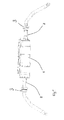
- FIG. 1 shows a split roll stabilizer according to the invention with a connected actuator 1.
- the actuator 1 is effectively arranged between two each formed as a torsion bar spring 2 stabilizer parts 2a. Both stabilizer parts 2a are each rotatably mounted via a stabilizer bearing 3 on a vehicle body, not shown here.
- the actuator 1 may comprise a motor with a connected gear, wherein an actuator housing can be connected to the one stabilizer part 2a and an output shaft to the other stabilizer part 2a.
- the connected stabilizer parts 2a are subjected to torsion.
- FIG. 2 shows an enlarged section FIG. 1
- a sensor 7 for non-contact measurement of the actuator torque has a magnetically coded primary sensor 5 and a magnetic field sensor 6a designated as a secondary sensor 6.
- the actuator torque is the torsional moment acting in the stabilizer parts 2a.
- the stabilizer part 2 a is provided with a connection part 4 a, which is connected to the actuator 1 for transmitting the torsional moment.
- the connecting part 4 a is formed as a flange 4 in the embodiment.
- the flange 4 is on the one hand rotatably connected to the stabilizer part 2a and the other on the other hand rotatably connected to the actuator 1.
- the flange 4 can be screwed to the actuator 1 with screws; the flange 4 can also be connected to the actuator 1 in a material, friction or non-positive manner.
- the flange 4 is hollow, wherein the stabilizer part 2 a formed annularly at its end engages in an annular shoulder 4 b of the flange 4.
- the flange 4 and the stabilizer part 2a are integrally connected to each other.
- the flange 4 has a sleeve-shaped portion 4c, on whose end remote from the annular shoulder 4b axial end integrally a radial flange 4d is formed.
- the radial board 4d is provided on its side facing the actuator not shown end face with a toothing 4e, which engages positively in a provided on the actuator counter teeth.
- the flange 4 is bolted to the actuator via screws not shown, wherein the screws are performed by provided in the radial board through holes.
- the flange 4 is formed of magnetostrictive material and magnetically coded and forms the primary sensor 5.
- the primary sensor 5 transmits the full torsional moment of the roll stabilizer. It may suffice to magnetically encode only the sleeve-shaped section 4c of the flange 4.
- the secondary sensor 6 is in the FIG. 2 alternatively arranged inside and outside the hollow flange 4.
- the secondary sensor 6 measures the change in the magnetic properties of the flange 4 caused by torsion of the primary sensor 5 due to the arrangement of the secondary sensor 6 within the hollow flange, a space-saving arrangement and effective protection of the sensor 7 are achieved
- split roll stabilizer differs from the previously described only in that instead of a cohesive connection between the flange 4 and the stabilizer part 2a a positive connection is provided.
- the secondary sensor 6 is disposed inside the hollow flange 4.
- the secondary sensor 6 can also be arranged radially outside the hollow flange 4.
- the modified hollow flange 4 has on the inner periphery of the sleeve-shaped portion 4c on an inner serrated profile 4f.
- the stabilizer part 2 a At its end facing the flange 4, the stabilizer part 2 a has an outer serrated profile 2 b on its outer circumference. The stabilizer part 2a is inserted with this end in the radial flange 4, wherein the serrated profiles 2b, 4f interlock positively to transmit torques.
- the primary sensors can be arranged on only one of the two stabilizer parts 2 a in the case of split roll stabilizers according to the invention; However, it is possible to provide both stabilizer parts 2a, each with a primary sensor 5. Both connected to the stabilizer parts 2a connecting parts 4a may be formed as a primary sensor 5, but only one secondary sensor 6 is assigned to one of the two primary sensors 5. In this way, a differentiation of the connection parts 4a into magnetically coded and magnetically non-coded connecting parts 4a is eliminated.
Landscapes
- Engineering & Computer Science (AREA)
- Mechanical Engineering (AREA)
- Vehicle Body Suspensions (AREA)
Priority Applications (1)
| Application Number | Priority Date | Filing Date | Title |
|---|---|---|---|
| EP17001501.0A EP3323647B1 (fr) | 2011-07-07 | 2012-04-27 | Barre stabilisatrice divisée |
Applications Claiming Priority (1)
| Application Number | Priority Date | Filing Date | Title |
|---|---|---|---|
| DE102011078821A DE102011078821A1 (de) | 2011-07-07 | 2011-07-07 | Geteilter Wankstabilisator |
Related Child Applications (3)
| Application Number | Title | Priority Date | Filing Date |
|---|---|---|---|
| EP17001501.0A Division EP3323647B1 (fr) | 2011-07-07 | 2012-04-27 | Barre stabilisatrice divisée |
| EP17001501.0A Division-Into EP3323647B1 (fr) | 2011-07-07 | 2012-04-27 | Barre stabilisatrice divisée |
| EP17001520.0 Division-Into | 2017-09-11 |
Publications (3)
| Publication Number | Publication Date |
|---|---|
| EP2543528A2 true EP2543528A2 (fr) | 2013-01-09 |
| EP2543528A3 EP2543528A3 (fr) | 2013-08-28 |
| EP2543528B1 EP2543528B1 (fr) | 2018-01-10 |
Family
ID=46052569
Family Applications (2)
| Application Number | Title | Priority Date | Filing Date |
|---|---|---|---|
| EP17001501.0A Active EP3323647B1 (fr) | 2011-07-07 | 2012-04-27 | Barre stabilisatrice divisée |
| EP12165905.6A Active EP2543528B1 (fr) | 2011-07-07 | 2012-04-27 | Barre stabilisatrice divisée |
Family Applications Before (1)
| Application Number | Title | Priority Date | Filing Date |
|---|---|---|---|
| EP17001501.0A Active EP3323647B1 (fr) | 2011-07-07 | 2012-04-27 | Barre stabilisatrice divisée |
Country Status (3)
| Country | Link |
|---|---|
| US (1) | US8770603B2 (fr) |
| EP (2) | EP3323647B1 (fr) |
| DE (1) | DE102011078821A1 (fr) |
Cited By (5)
| Publication number | Priority date | Publication date | Assignee | Title |
|---|---|---|---|---|
| DE102013205903A1 (de) | 2013-04-04 | 2014-10-09 | Schaeffler Technologies Gmbh & Co. Kg | Fahrwerksaktuatorvorrichtung für ein Fahrzeug |
| DE102013223424A1 (de) | 2013-07-17 | 2015-01-22 | Schaeffler Technologies Gmbh & Co. Kg | Verfahren für den Betrieb eines Kraftfahrzeugs zur Erkennung einer Überbeanspruchung eines Wankstabilisators |
| DE102013223073A1 (de) | 2013-11-13 | 2015-05-13 | Schaeffler Technologies Gmbh & Co. Kg | Wankstabilisator |
| EP2980551B1 (fr) * | 2014-07-30 | 2018-05-23 | MAHA Maschinenbau Haldenwang GmbH & Co. KG | Banc d'essai de freinage de vehicule automobile |
| DE102019101841A1 (de) | 2019-01-25 | 2020-07-30 | Schaeffler Technologies AG & Co. KG | Wankstabilisator für ein Kraftfahrzeug sowie Verfahren zur Herstellung eines solchen Wankstabilisators |
Families Citing this family (10)
| Publication number | Priority date | Publication date | Assignee | Title |
|---|---|---|---|---|
| DE102011078819A1 (de) * | 2010-09-30 | 2012-04-05 | Schaeffler Technologies Gmbh & Co. Kg | Geteilter Wankstabilisator |
| DE102013219761B3 (de) * | 2013-09-30 | 2015-01-15 | Schaeffler Technologies Gmbh & Co. Kg | Anordnung und Verfahren zum Messen eines Drehmomentes an einem Maschinenelement sowie Wankstabilisator |
| DE102014208335A1 (de) | 2014-05-05 | 2015-11-05 | Schaeffler Technologies AG & Co. KG | Wankstabilisator |
| DE102014208334A1 (de) | 2014-05-05 | 2015-11-05 | Schaeffler Technologies AG & Co. KG | Wankstabilisator |
| DE102014208485A1 (de) * | 2014-05-07 | 2015-11-12 | Schaeffler Technologies AG & Co. KG | Aktiver Wankstabilisator |
| DE102014213841A1 (de) | 2014-07-16 | 2016-01-21 | Schaeffler Technologies AG & Co. KG | Magnetostriktive Drehmomentsensoranordnung mit Magnetfeldschirmung |
| WO2016072843A1 (fr) * | 2014-11-05 | 2016-05-12 | Eminent Products B.V. | Suspension de roue, procédé pour déterminer une quantité mécanique dans une suspension de roue et véhicule comprenant une telle suspension de roue |
| DE102015105284A1 (de) * | 2015-04-08 | 2016-10-13 | Ovalo Gmbh | Verfahren zum Herstellen eines Torsionsstabes |
| DE102017106877A1 (de) | 2017-03-30 | 2018-10-04 | Schaeffler Technologies AG & Co. KG | Geteilter Wankstabilisator und Flansch hierfür |
| DE102018102380A1 (de) * | 2018-02-02 | 2019-08-08 | Schaeffler Technologies AG & Co. KG | Elektromechanischer Aktuator |
Citations (1)
| Publication number | Priority date | Publication date | Assignee | Title |
|---|---|---|---|---|
| WO2006013093A2 (fr) | 2004-08-02 | 2006-02-09 | Nctengineering Gmbh | Electronique de capteur |
Family Cites Families (10)
| Publication number | Priority date | Publication date | Assignee | Title |
|---|---|---|---|---|
| JPS6060024A (ja) * | 1983-09-09 | 1985-04-06 | Nissan Motor Co Ltd | 車両におけるロ−ル剛性制御装置 |
| DE10126928B4 (de) * | 2001-06-01 | 2006-06-29 | ZF Lemförder Metallwaren AG | Stabilisator für ein Kraftfahrzeug |
| US20070247224A1 (en) * | 2004-08-02 | 2007-10-25 | Lutz May | Sensor Electronic |
| DE102006040109A1 (de) | 2006-08-26 | 2008-02-28 | Bayerische Motoren Werke Ag | Aktiver, geteilter Kraftfahrzeugstabilisator mit eingebauten Schwenkmotor |
| US7832739B2 (en) * | 2006-11-06 | 2010-11-16 | American Axle & Manufacturing, Inc. | Apparatus and method for coupling a disconnectable stabilizer bar |
| JP4958066B2 (ja) * | 2006-11-09 | 2012-06-20 | アイシン精機株式会社 | スタビライザ制御装置 |
| DE102008001006A1 (de) * | 2008-04-04 | 2009-11-12 | Zf Friedrichshafen Ag | Radaufhängung für ein Fahrzeug |
| DE102009028386A1 (de) * | 2009-08-10 | 2011-02-17 | Zf Friedrichshafen Ag | Vorrichtung zum Variieren eines Wankwinkels einer Fahrzeugkarosserie im Bereich wenigstens einer Fahrzeugachse |
| DE102009047222A1 (de) * | 2009-11-27 | 2011-06-01 | Robert Bosch Gmbh | Sensoranordnung zum Ermitteln eines Drehmoments und zur Indexerkennung |
| DE102010037555B4 (de) * | 2010-09-15 | 2019-01-17 | Ovalo Gmbh | Aktiver Fahrwerksstabilisator, Aktuator, Fahrzeug und Verfahren zur Steuerung und/oder Regelungeines Fahrwerkstabilisators |
-
2011
- 2011-07-07 DE DE102011078821A patent/DE102011078821A1/de not_active Withdrawn
-
2012
- 2012-04-27 EP EP17001501.0A patent/EP3323647B1/fr active Active
- 2012-04-27 EP EP12165905.6A patent/EP2543528B1/fr active Active
- 2012-06-26 US US13/533,197 patent/US8770603B2/en active Active
Patent Citations (1)
| Publication number | Priority date | Publication date | Assignee | Title |
|---|---|---|---|---|
| WO2006013093A2 (fr) | 2004-08-02 | 2006-02-09 | Nctengineering Gmbh | Electronique de capteur |
Cited By (8)
| Publication number | Priority date | Publication date | Assignee | Title |
|---|---|---|---|---|
| DE102013205903A1 (de) | 2013-04-04 | 2014-10-09 | Schaeffler Technologies Gmbh & Co. Kg | Fahrwerksaktuatorvorrichtung für ein Fahrzeug |
| US9221316B2 (en) | 2013-04-04 | 2015-12-29 | Schaeffler Technologies AG & Co. KG | Chassis actuator device for a vehicle |
| DE102013205903B4 (de) | 2013-04-04 | 2021-07-22 | Schaeffler Technologies AG & Co. KG | Fahrwerksaktuatorvorrichtung für ein Fahrzeug |
| DE102013223424A1 (de) | 2013-07-17 | 2015-01-22 | Schaeffler Technologies Gmbh & Co. Kg | Verfahren für den Betrieb eines Kraftfahrzeugs zur Erkennung einer Überbeanspruchung eines Wankstabilisators |
| DE102013223424B4 (de) * | 2013-07-17 | 2021-03-04 | Schaeffler Technologies AG & Co. KG | Verfahren für den Betrieb eines Kraftfahrzeugs zur Erkennung einer Überbeanspruchung eines Wankstabilisators |
| DE102013223073A1 (de) | 2013-11-13 | 2015-05-13 | Schaeffler Technologies Gmbh & Co. Kg | Wankstabilisator |
| EP2980551B1 (fr) * | 2014-07-30 | 2018-05-23 | MAHA Maschinenbau Haldenwang GmbH & Co. KG | Banc d'essai de freinage de vehicule automobile |
| DE102019101841A1 (de) | 2019-01-25 | 2020-07-30 | Schaeffler Technologies AG & Co. KG | Wankstabilisator für ein Kraftfahrzeug sowie Verfahren zur Herstellung eines solchen Wankstabilisators |
Also Published As
| Publication number | Publication date |
|---|---|
| EP3323647B1 (fr) | 2019-11-06 |
| EP3323647A1 (fr) | 2018-05-23 |
| US20130009374A1 (en) | 2013-01-10 |
| EP2543528A3 (fr) | 2013-08-28 |
| EP2543528B1 (fr) | 2018-01-10 |
| DE102011078821A1 (de) | 2013-01-10 |
| US8770603B2 (en) | 2014-07-08 |
Similar Documents
| Publication | Publication Date | Title |
|---|---|---|
| EP2543528B1 (fr) | Barre stabilisatrice divisée | |
| EP2621743B1 (fr) | Stabilisateur de roulis en deux parties | |
| EP2090497B1 (fr) | Dispositif de détermination d'un angle de torsion | |
| DE102013219761B3 (de) | Anordnung und Verfahren zum Messen eines Drehmomentes an einem Maschinenelement sowie Wankstabilisator | |
| DE102010037555B4 (de) | Aktiver Fahrwerksstabilisator, Aktuator, Fahrzeug und Verfahren zur Steuerung und/oder Regelungeines Fahrwerkstabilisators | |
| EP3307604B1 (fr) | Actionneur à rétroaction d'un dispositif de direction | |
| EP3114010A1 (fr) | Arbre de direction pour système de direction de véhicule automobile | |
| EP3114449A1 (fr) | Pièce structurale comprenant un élément de mesure comportant au moins un capteur | |
| DE102011053278A1 (de) | Entkoppelbarer Aktuator, insbesondere mit elektromechanischem Antrieb | |
| EP3840968A1 (fr) | Stabilisateur anti-roulis et dispositif de capteur pour un stabilisateur anti-roulis | |
| DE102011075890A1 (de) | Wankstabilisator eines Kraftfahrzeuges | |
| DE19924002A1 (de) | Sensor, insbesondere magnetiostriktiver oder magnetoelastischer Sensor | |
| DE102014208334A1 (de) | Wankstabilisator | |
| DE102013001829A1 (de) | Drehwinkel- und Torsionswinkelsensor | |
| DE102011053277A1 (de) | Stabilisator mit einem integrierten Aktuator | |
| EP3762680A1 (fr) | Mesure de variatons mécaniques | |
| WO2020211891A1 (fr) | Actionneur manuel doté d'un système de capteurs pour la détection du couple | |
| DE102010027959A1 (de) | Vorrichtung zur Erfassung des über eine Hohlwelle, insbesondere einen Abschnitt eines Querstabilisators eines Fahrzeugs, übertragenen Drehmoments | |
| DE102005055995A1 (de) | Lageranordnung und Verfahren zur Einstellung der Vorspannung in der Lageranordnung | |
| EP1617196B1 (fr) | Capteur de forces et/ou de couples | |
| DE102018211386A1 (de) | Vorrichtung eines Drehmomentsensors sowie Verfahren zum Betreiben eines Drehmomentsensors | |
| DE102014221129A1 (de) | Wankstabilisator für ein Kraftfahrzeug | |
| DE102022102604A1 (de) | Relativverdrehung-Erfassungsvorrichtung und Tretkurbelanordnung | |
| DE102007000596A1 (de) | Verfahren und Vorrichtung zum Messen eines von einer Welle übertragenen Drehmomentes | |
| EP3882596A2 (fr) | Agencement de mesure sur un arbre rotatif |
Legal Events
| Date | Code | Title | Description |
|---|---|---|---|
| PUAI | Public reference made under article 153(3) epc to a published international application that has entered the european phase |
Free format text: ORIGINAL CODE: 0009012 |
|
| 17P | Request for examination filed |
Effective date: 20120427 |
|
| AK | Designated contracting states |
Kind code of ref document: A2 Designated state(s): AL AT BE BG CH CY CZ DE DK EE ES FI FR GB GR HR HU IE IS IT LI LT LU LV MC MK MT NL NO PL PT RO RS SE SI SK SM TR |
|
| AX | Request for extension of the european patent |
Extension state: BA ME |
|
| PUAL | Search report despatched |
Free format text: ORIGINAL CODE: 0009013 |
|
| AK | Designated contracting states |
Kind code of ref document: A3 Designated state(s): AL AT BE BG CH CY CZ DE DK EE ES FI FR GB GR HR HU IE IS IT LI LT LU LV MC MK MT NL NO PL PT RO RS SE SI SK SM TR |
|
| AX | Request for extension of the european patent |
Extension state: BA ME |
|
| RIC1 | Information provided on ipc code assigned before grant |
Ipc: B60G 21/055 20060101ALI20130723BHEP Ipc: B60G 17/019 20060101AFI20130723BHEP |
|
| 17Q | First examination report despatched |
Effective date: 20130816 |
|
| RAP1 | Party data changed (applicant data changed or rights of an application transferred) |
Owner name: SCHAEFFLER TECHNOLOGIES GMBH & CO. KG |
|
| RBV | Designated contracting states (corrected) |
Designated state(s): AL AT BE BG CH CY CZ DE DK EE ES FI FR GB GR HR HU IE IS IT LI LT LU LV MC MK MT NL NO PL PT RO RS SE SI SK SM TR |
|
| RAP1 | Party data changed (applicant data changed or rights of an application transferred) |
Owner name: SCHAEFFLER TECHNOLOGIES AG & CO. KG |
|
| GRAP | Despatch of communication of intention to grant a patent |
Free format text: ORIGINAL CODE: EPIDOSNIGR1 |
|
| INTG | Intention to grant announced |
Effective date: 20170823 |
|
| GRAS | Grant fee paid |
Free format text: ORIGINAL CODE: EPIDOSNIGR3 |
|
| GRAA | (expected) grant |
Free format text: ORIGINAL CODE: 0009210 |
|
| AK | Designated contracting states |
Kind code of ref document: B1 Designated state(s): AL AT BE BG CH CY CZ DE DK EE ES FI FR GB GR HR HU IE IS IT LI LT LU LV MC MK MT NL NO PL PT RO RS SE SI SK SM TR |
|
| REG | Reference to a national code |
Ref country code: GB Ref legal event code: FG4D Free format text: NOT ENGLISH |
|
| REG | Reference to a national code |
Ref country code: CH Ref legal event code: EP Ref country code: AT Ref legal event code: REF Ref document number: 961978 Country of ref document: AT Kind code of ref document: T Effective date: 20180115 |
|
| REG | Reference to a national code |
Ref country code: IE Ref legal event code: FG4D Free format text: LANGUAGE OF EP DOCUMENT: GERMAN |
|
| REG | Reference to a national code |
Ref country code: DE Ref legal event code: R096 Ref document number: 502012011964 Country of ref document: DE |
|
| REG | Reference to a national code |
Ref country code: FR Ref legal event code: PLFP Year of fee payment: 7 |
|
| REG | Reference to a national code |
Ref country code: NL Ref legal event code: MP Effective date: 20180110 |
|
| PG25 | Lapsed in a contracting state [announced via postgrant information from national office to epo] |
Ref country code: NL Free format text: LAPSE BECAUSE OF FAILURE TO SUBMIT A TRANSLATION OF THE DESCRIPTION OR TO PAY THE FEE WITHIN THE PRESCRIBED TIME-LIMIT Effective date: 20180110 |
|
| PG25 | Lapsed in a contracting state [announced via postgrant information from national office to epo] |
Ref country code: ES Free format text: LAPSE BECAUSE OF FAILURE TO SUBMIT A TRANSLATION OF THE DESCRIPTION OR TO PAY THE FEE WITHIN THE PRESCRIBED TIME-LIMIT Effective date: 20180110 Ref country code: CY Free format text: LAPSE BECAUSE OF FAILURE TO SUBMIT A TRANSLATION OF THE DESCRIPTION OR TO PAY THE FEE WITHIN THE PRESCRIBED TIME-LIMIT Effective date: 20180110 Ref country code: LT Free format text: LAPSE BECAUSE OF FAILURE TO SUBMIT A TRANSLATION OF THE DESCRIPTION OR TO PAY THE FEE WITHIN THE PRESCRIBED TIME-LIMIT Effective date: 20180110 Ref country code: NO Free format text: LAPSE BECAUSE OF FAILURE TO SUBMIT A TRANSLATION OF THE DESCRIPTION OR TO PAY THE FEE WITHIN THE PRESCRIBED TIME-LIMIT Effective date: 20180410 Ref country code: HR Free format text: LAPSE BECAUSE OF FAILURE TO SUBMIT A TRANSLATION OF THE DESCRIPTION OR TO PAY THE FEE WITHIN THE PRESCRIBED TIME-LIMIT Effective date: 20180110 Ref country code: FI Free format text: LAPSE BECAUSE OF FAILURE TO SUBMIT A TRANSLATION OF THE DESCRIPTION OR TO PAY THE FEE WITHIN THE PRESCRIBED TIME-LIMIT Effective date: 20180110 |
|
| PG25 | Lapsed in a contracting state [announced via postgrant information from national office to epo] |
Ref country code: IS Free format text: LAPSE BECAUSE OF FAILURE TO SUBMIT A TRANSLATION OF THE DESCRIPTION OR TO PAY THE FEE WITHIN THE PRESCRIBED TIME-LIMIT Effective date: 20180510 Ref country code: RS Free format text: LAPSE BECAUSE OF FAILURE TO SUBMIT A TRANSLATION OF THE DESCRIPTION OR TO PAY THE FEE WITHIN THE PRESCRIBED TIME-LIMIT Effective date: 20180110 Ref country code: PL Free format text: LAPSE BECAUSE OF FAILURE TO SUBMIT A TRANSLATION OF THE DESCRIPTION OR TO PAY THE FEE WITHIN THE PRESCRIBED TIME-LIMIT Effective date: 20180110 Ref country code: SE Free format text: LAPSE BECAUSE OF FAILURE TO SUBMIT A TRANSLATION OF THE DESCRIPTION OR TO PAY THE FEE WITHIN THE PRESCRIBED TIME-LIMIT Effective date: 20180110 Ref country code: LV Free format text: LAPSE BECAUSE OF FAILURE TO SUBMIT A TRANSLATION OF THE DESCRIPTION OR TO PAY THE FEE WITHIN THE PRESCRIBED TIME-LIMIT Effective date: 20180110 Ref country code: GR Free format text: LAPSE BECAUSE OF FAILURE TO SUBMIT A TRANSLATION OF THE DESCRIPTION OR TO PAY THE FEE WITHIN THE PRESCRIBED TIME-LIMIT Effective date: 20180411 Ref country code: BG Free format text: LAPSE BECAUSE OF FAILURE TO SUBMIT A TRANSLATION OF THE DESCRIPTION OR TO PAY THE FEE WITHIN THE PRESCRIBED TIME-LIMIT Effective date: 20180410 |
|
| PG25 | Lapsed in a contracting state [announced via postgrant information from national office to epo] |
Ref country code: MT Free format text: LAPSE BECAUSE OF FAILURE TO SUBMIT A TRANSLATION OF THE DESCRIPTION OR TO PAY THE FEE WITHIN THE PRESCRIBED TIME-LIMIT Effective date: 20180110 |
|
| REG | Reference to a national code |
Ref country code: DE Ref legal event code: R097 Ref document number: 502012011964 Country of ref document: DE |
|
| PG25 | Lapsed in a contracting state [announced via postgrant information from national office to epo] |
Ref country code: RO Free format text: LAPSE BECAUSE OF FAILURE TO SUBMIT A TRANSLATION OF THE DESCRIPTION OR TO PAY THE FEE WITHIN THE PRESCRIBED TIME-LIMIT Effective date: 20180110 Ref country code: AL Free format text: LAPSE BECAUSE OF FAILURE TO SUBMIT A TRANSLATION OF THE DESCRIPTION OR TO PAY THE FEE WITHIN THE PRESCRIBED TIME-LIMIT Effective date: 20180110 Ref country code: IT Free format text: LAPSE BECAUSE OF FAILURE TO SUBMIT A TRANSLATION OF THE DESCRIPTION OR TO PAY THE FEE WITHIN THE PRESCRIBED TIME-LIMIT Effective date: 20180110 Ref country code: EE Free format text: LAPSE BECAUSE OF FAILURE TO SUBMIT A TRANSLATION OF THE DESCRIPTION OR TO PAY THE FEE WITHIN THE PRESCRIBED TIME-LIMIT Effective date: 20180110 |
|
| PLBE | No opposition filed within time limit |
Free format text: ORIGINAL CODE: 0009261 |
|
| STAA | Information on the status of an ep patent application or granted ep patent |
Free format text: STATUS: NO OPPOSITION FILED WITHIN TIME LIMIT |
|
| PG25 | Lapsed in a contracting state [announced via postgrant information from national office to epo] |
Ref country code: DK Free format text: LAPSE BECAUSE OF FAILURE TO SUBMIT A TRANSLATION OF THE DESCRIPTION OR TO PAY THE FEE WITHIN THE PRESCRIBED TIME-LIMIT Effective date: 20180110 Ref country code: SM Free format text: LAPSE BECAUSE OF FAILURE TO SUBMIT A TRANSLATION OF THE DESCRIPTION OR TO PAY THE FEE WITHIN THE PRESCRIBED TIME-LIMIT Effective date: 20180110 Ref country code: SK Free format text: LAPSE BECAUSE OF FAILURE TO SUBMIT A TRANSLATION OF THE DESCRIPTION OR TO PAY THE FEE WITHIN THE PRESCRIBED TIME-LIMIT Effective date: 20180110 Ref country code: CZ Free format text: LAPSE BECAUSE OF FAILURE TO SUBMIT A TRANSLATION OF THE DESCRIPTION OR TO PAY THE FEE WITHIN THE PRESCRIBED TIME-LIMIT Effective date: 20180110 Ref country code: MC Free format text: LAPSE BECAUSE OF FAILURE TO SUBMIT A TRANSLATION OF THE DESCRIPTION OR TO PAY THE FEE WITHIN THE PRESCRIBED TIME-LIMIT Effective date: 20180110 |
|
| REG | Reference to a national code |
Ref country code: CH Ref legal event code: PL |
|
| 26N | No opposition filed |
Effective date: 20181011 |
|
| REG | Reference to a national code |
Ref country code: BE Ref legal event code: MM Effective date: 20180430 |
|
| REG | Reference to a national code |
Ref country code: IE Ref legal event code: MM4A |
|
| PG25 | Lapsed in a contracting state [announced via postgrant information from national office to epo] |
Ref country code: LU Free format text: LAPSE BECAUSE OF NON-PAYMENT OF DUE FEES Effective date: 20180427 |
|
| PG25 | Lapsed in a contracting state [announced via postgrant information from national office to epo] |
Ref country code: LI Free format text: LAPSE BECAUSE OF NON-PAYMENT OF DUE FEES Effective date: 20180430 Ref country code: SI Free format text: LAPSE BECAUSE OF FAILURE TO SUBMIT A TRANSLATION OF THE DESCRIPTION OR TO PAY THE FEE WITHIN THE PRESCRIBED TIME-LIMIT Effective date: 20180110 Ref country code: CH Free format text: LAPSE BECAUSE OF NON-PAYMENT OF DUE FEES Effective date: 20180430 Ref country code: BE Free format text: LAPSE BECAUSE OF NON-PAYMENT OF DUE FEES Effective date: 20180430 |
|
| PG25 | Lapsed in a contracting state [announced via postgrant information from national office to epo] |
Ref country code: IE Free format text: LAPSE BECAUSE OF NON-PAYMENT OF DUE FEES Effective date: 20180427 |
|
| REG | Reference to a national code |
Ref country code: AT Ref legal event code: MM01 Ref document number: 961978 Country of ref document: AT Kind code of ref document: T Effective date: 20180427 |
|
| PG25 | Lapsed in a contracting state [announced via postgrant information from national office to epo] |
Ref country code: AT Free format text: LAPSE BECAUSE OF NON-PAYMENT OF DUE FEES Effective date: 20180427 |
|
| PG25 | Lapsed in a contracting state [announced via postgrant information from national office to epo] |
Ref country code: TR Free format text: LAPSE BECAUSE OF FAILURE TO SUBMIT A TRANSLATION OF THE DESCRIPTION OR TO PAY THE FEE WITHIN THE PRESCRIBED TIME-LIMIT Effective date: 20180110 |
|
| PG25 | Lapsed in a contracting state [announced via postgrant information from national office to epo] |
Ref country code: PT Free format text: LAPSE BECAUSE OF FAILURE TO SUBMIT A TRANSLATION OF THE DESCRIPTION OR TO PAY THE FEE WITHIN THE PRESCRIBED TIME-LIMIT Effective date: 20180110 Ref country code: HU Free format text: LAPSE BECAUSE OF FAILURE TO SUBMIT A TRANSLATION OF THE DESCRIPTION OR TO PAY THE FEE WITHIN THE PRESCRIBED TIME-LIMIT; INVALID AB INITIO Effective date: 20120427 |
|
| PG25 | Lapsed in a contracting state [announced via postgrant information from national office to epo] |
Ref country code: MK Free format text: LAPSE BECAUSE OF NON-PAYMENT OF DUE FEES Effective date: 20180110 |
|
| P01 | Opt-out of the competence of the unified patent court (upc) registered |
Effective date: 20230522 |
|
| PGFP | Annual fee paid to national office [announced via postgrant information from national office to epo] |
Ref country code: DE Payment date: 20250618 Year of fee payment: 14 |
|
| PGFP | Annual fee paid to national office [announced via postgrant information from national office to epo] |
Ref country code: GB Payment date: 20250423 Year of fee payment: 14 |
|
| PGFP | Annual fee paid to national office [announced via postgrant information from national office to epo] |
Ref country code: FR Payment date: 20250425 Year of fee payment: 14 |