EP2543773B1 - Schachtdeckel - Google Patents
Schachtdeckel Download PDFInfo
- Publication number
- EP2543773B1 EP2543773B1 EP12174664.8A EP12174664A EP2543773B1 EP 2543773 B1 EP2543773 B1 EP 2543773B1 EP 12174664 A EP12174664 A EP 12174664A EP 2543773 B1 EP2543773 B1 EP 2543773B1
- Authority
- EP
- European Patent Office
- Prior art keywords
- manhole cover
- filling
- concrete
- accordance
- aforementioned
- Prior art date
- Legal status (The legal status is an assumption and is not a legal conclusion. Google has not performed a legal analysis and makes no representation as to the accuracy of the status listed.)
- Active
Links
Images
Classifications
-
- E—FIXED CONSTRUCTIONS
- E02—HYDRAULIC ENGINEERING; FOUNDATIONS; SOIL SHIFTING
- E02D—FOUNDATIONS; EXCAVATIONS; EMBANKMENTS; UNDERGROUND OR UNDERWATER STRUCTURES
- E02D29/00—Independent underground or underwater structures; Retaining walls
- E02D29/12—Manhole shafts; Other inspection or access chambers; Accessories therefor
- E02D29/14—Covers for manholes or the like; Frames for covers
-
- Y—GENERAL TAGGING OF NEW TECHNOLOGICAL DEVELOPMENTS; GENERAL TAGGING OF CROSS-SECTIONAL TECHNOLOGIES SPANNING OVER SEVERAL SECTIONS OF THE IPC; TECHNICAL SUBJECTS COVERED BY FORMER USPC CROSS-REFERENCE ART COLLECTIONS [XRACs] AND DIGESTS
- Y10—TECHNICAL SUBJECTS COVERED BY FORMER USPC
- Y10T—TECHNICAL SUBJECTS COVERED BY FORMER US CLASSIFICATION
- Y10T137/00—Fluid handling
- Y10T137/6851—With casing, support, protector or static constructional installations
- Y10T137/6966—Static constructional installations
- Y10T137/6991—Ground supporting enclosure
- Y10T137/6995—Valve and meter wells
- Y10T137/7021—Covers
Definitions
- the invention relates to a manhole cover according to the preamble of claim 1.
- a manhole cover which consists only of the two components of a floor and a filling.
- material for the bottom of the manhole cover the same material is preferably used as for a manhole, which is to be closed with the manhole cover, is mentioned as an example of high density polyethylene.
- the manhole serves as access to the sewer system for inspection purposes. Where the manhole cover can be arranged and what loads it withstands is not mentioned.
- U1 From the DE 298 01 640 U1 is a generic foreign manhole cover known.
- This manhole cover has at the bottom of an outer shell made of sheet metal, in which then the actual bottom is poured, which has a certain layer thickness, and in which case the filling is poured into the ground.
- This overall three-layer structure of the manhole cover is complex in terms of production technology. The components or materials used are relatively expensive, so z.
- the outer shell provided as a lost molding made of sheet metal, and the bottom is either made of cast steel or - in contrast, larger dimensions - made of polymer concrete.
- the filling also consists of Polymer concrete.
- the manhole cover is to be arranged in roadways and is designed for correspondingly high load capacities due to a high volume of traffic, high mechanical loads and aggressive weather conditions.
- a manhole cover known, which is designed as a filled hollow body.
- a shell encloses the filling on all sides, so that the filling must be introduced through a filling opening in the shell.
- the shell is preferably made of polyethylene, and the filling is preferably made of concrete.
- Lever as are designed as a substantially U-shaped, downwardly open bracket. They can be pulled out of the manhole cover in a vertical direction so that they can be picked up to lift the manhole cover. In the lowered state of rest, the lever pockets each dive into a recess which is provided in the surface of the manhole cover.
- the manufacture of the manhole cover is complicated because a hollow body must be filled, the openings of the hollow body, which are required for the vertical mobility of the lever ashes, either complicate this filling, or later, after hardening of the filling, the manhole cover must be repeatedly pierced, to create channels through which the lever pockets can extend.
- a lid which does not serve as a manhole cover, but serves to cover trenches in road surfaces, and which is designed as a metal plate.
- the lid is used when the excavation work is stopped and the road surface is opened for traffic.
- the metal plates are dimensioned accordingly stable and therefore heavy.
- Omega-shaped lever pockets are provided, which are rotatably mounted at its two ends in the cover plate and from a down-hanging rest position in an upright Use position can be pivoted in which they protrude above the surface of the lid upwards.
- a lid having a core with a cell structure and an outer closed cladding layer of a fiber reinforced resin is known.
- the lid should expressly endure high dynamic loads, so that z. B. in traffic, the vehicles can drive over the lid.
- the core can, for. B. consist of several Balsaholzblöcken, and the cladding layer of a glass fiber reinforced epoxy or polyester resin.
- the manufacture of the lid is complicated because two separate parts of the coating layer are produced. A first part of the cladding layer forms a trough, in which then the individual components of the core are inserted. Subsequently, the core is covered with the second part of the cladding layer.
- both parts of the cladding layer must be bonded together at all points of contact that they have with each other and with the core structure, and that any air pockets must be avoided to provide a substantially monolithic mass.
- Tools for lifting the lid are not provided, but rather the lid has anchor holes which allow the insertion of ground anchors, so that the lid can be fixed by means of these ground anchors to the ground.
- manhole covers outside of roads are required.
- inspection and maintenance shafts may be provided on private residential land, e.g. As in garage entrances to allow access to the house connections of the sewer for cleaning or inspection purposes.
- a mechanical load by heavy trucks is just as little given here as a high volume of traffic or a high road salt load in winter.
- Conventional manhole covers are therefore often overqualified for these applications and because of their complex production or unnecessarily expensive because of the expensive materials used.
- the invention has for its object to improve a generic manhole cover to the effect that this is possible to produce inexpensively.
- the invention proposes, in other words, to create a production-optimized manhole cover, which does not necessarily have to withstand particularly high loads, as is the case for example in traffic, but for example in driveways, on private land u.
- a production-optimized manhole cover which does not necessarily have to withstand particularly high loads, as is the case for example in traffic, but for example in driveways, on private land u.
- the soil has a layer thickness of at most 5 mm.
- sufficient inherent stability of the soil is guaranteed to make it suitable as a casting mold, so as a lost formwork for the concrete filling.
- the most economical production of the manhole cover is supported by this comparatively low material thickness of the soil.
- the floor consists of glass fiber reinforced plastic.
- the soil can also contribute to the strength and compressive strength of the manhole cover contribute.
- the soil is economical to produce, so that it can easily remain as a lost formwork even after pouring the filling at this.
- a coating, impregnation or other treatment of the concrete filling on its underside is therefore not required to protect against influences that act on the manhole cover from the shaft. Rather, the manhole cover is usable without post-processing, after the concrete filling is cured in the bottom shell.
- thermosetting plastic As plastic, a thermosetting plastic is used. This has sufficiently good mechanical properties and a very good economy.
- lever ashes may be provided, so that two diametrically opposite points are provided for handling the manhole cover and the manhole cover can be raised or lowered as simply as possible and without jamming.
- Both lever ashtrays can be made as equal parts, so that only two different types of parts must be prefabricated, namely the ground and the lever ashes, with a bottom and one or two lever ashes are used for each manhole cover.
- the filling itself need not be prefabricated as a component, but is poured in a flowable state into the soil, which thus forms the formwork for the concrete filling.
- the proposed manhole cover can be designed for a load of 15t to 20t, in contrast to, for example, manhole covers that are used on public roads and can be loaded up to 40t.
- the manhole cover is technically designed for a load of only 5 t, so that correspondingly inexpensive materials can be used or the layer thicknesses of the floor or of the filling can be correspondingly low.
- the technically possible load capacity of 5t means a license of up to 1.5t for use in public areas, eg. B.
- the manhole cover can advantageously be structurally designed in terms of its materials and layer thicknesses that it is destroyed only at a load of 6t, said force at which the destruction occurs, is referred to as a bursting force.
- the cost-effective production of the manhole cover can be advantageously supported by the fact that not only one, but two lever pockets are provided, which are arranged diametrically opposite one another. This way you can the lid can be raised or lowered without jamming, which reduces the burden of the manhole cover compared to the use of only a single lever as, for example, edge loads are reduced by an oblique orientation of the lid.
- the load on the individual lifting lugs and the places where the lifting lugs are anchored in the filling is also reduced by using two lifting lugs.
- the manhole cover must be designed for these only lower loads.
- a lever ashes are formed from a wire, preferably a stainless steel wire whose two ends are anchored in the filling, wherein in the filling a trough is provided, through which extends this wire, so that the middle part of the wire runs within the trough and can be tracked with appropriate lifting tools.
- a recessed arrangement of the lever ashes is ensured so that they do not protrude beyond the surface of the manhole cover, which reduces the burden of the lever ashes when passing, driving over o. The like.
- the manhole cover is preferably a stainless steel wire whose two ends are anchored in the filling, wherein in the filling a trough is provided, through which extends this wire, so that the middle part of the wire runs within the trough and can be tracked with appropriate lifting tools.
- the lever ashtray can be anchored immovably in the filling, instead of being movably mounted between a rest position and a use position.
- the production of the manhole cover is simplified in this way and can be carried out more economically. Since it can be assumed that the manhole cover in most applications not daily or weekly, but at most several months or even several years away from the shaft, is associated with additional costs, the handling of the lever as possibly facilitating embodiment of Manhole cover in this majority of cases not economically useful. In view of the long intervals between use of the lever ashes, it is also questionable whether, if necessary, it can actually be moved without any problems or, if necessary, is difficult to navigate due to protection, corrosion and similar influences, in which cases the desired easier handling of the lever ashes would not have been realized.
- the wire is not rectilinear but arcuate, wherein it has a curved upwardly extending middle part.
- the smallest possible depression of the trough in the filling as large a free space below the middle part of the lever ashes ensures, so that it can be easily detected - even if it is immovably anchored in the filling.
- a weakening in the filling which can be effected by the trough and the correspondingly reduced material thickness of the filling, can be kept as low as possible by a flat design of the trough. In this way, a sufficiently stable manhole cover can be created with the least possible use of materials.
- the GRP material has no complicated longitudinal rovings, which have particularly good mechanical properties, but the GRP material may advantageously comprise non-directional fiber mats as reinforcing fibers, which are more economical to obtain than the aforementioned rovings.
- the achievable by the concrete filling properties of the manhole cover are sufficient anyway, so that the achievable by the soil strength and resilience improvement of the manhole cover ensures sufficient load capacity for the manhole cover even when using such non-directional fiber mats in the ground.
- the concrete used as filling must be for the desired strength of the manhole cover no high performance or polymer concrete o. The like., So concrete with special aggregates, but the concrete may be designed for economic reasons as pure mineral concrete.
- the sufficient strength or load capacity of the manhole cover can be easily achieved even with such a simple designed concrete material, for example, if the additives used are assembled in a suitable manner, as is known in practice, for example by sand of a certain grain size is used, ie a certain so-called grading curve, so that by matching the individual, different sized aggregates in the concrete already sufficient strength values for the filling, and thus for the entire manhole cover are possible.
- 1 designates as a whole a manhole cover which essentially consists of concrete, the concrete forming a filling 2 which is poured into a plastic shell which forms a bottom 3 of the manhole cover 1.
- the bottom 3 is designed shell-shaped and forms not only the bottom, but also a circumferential side edge.
- two troughs 4 are provided, which are diametrically opposed to each other and through which extends a wire forming a lever ashtray 5.
- each wire is approximately wave-shaped and is anchored with its two ends in the filling 2, while the middle part of this wire extends upwards and through the trough 4.
- the middle part of each wire extends as Lever ashes 5 at a great distance higher than it corresponds to the deepest bottom of the trough 4, so that the lever ashes 5 can be easily understood and accordingly the manhole cover 1 can be handled easily.
- a manhole cover 1 For the production of a manhole cover 1, only three different components are used, namely, first, the bottom 3, in which then the filling 2 is filled, wherein a wire is poured as a lever ashtray 5 and enclosed by the filling 2. Of these three different components of the wire or the lever ashtray 5 is used in duplicate, but manufacturing technology to produce only three different components to create the manhole cover 1.
- the concrete of the filling 2 is a comparatively simple and inexpensive concrete material, as a purely mineral concrete without polymer additives o. The like. Does not have fiber reinforcements o. The like., So that he for the required strength of the manhole cover 1 a particularly economical production of Manhole cover allows.
Landscapes
- Engineering & Computer Science (AREA)
- Environmental & Geological Engineering (AREA)
- Life Sciences & Earth Sciences (AREA)
- General Life Sciences & Earth Sciences (AREA)
- Mining & Mineral Resources (AREA)
- Paleontology (AREA)
- Civil Engineering (AREA)
- General Engineering & Computer Science (AREA)
- Structural Engineering (AREA)
- Underground Structures, Protecting, Testing And Restoring Foundations (AREA)
Description
- Die Erfindung betrifft einen Schachtdeckel nach dem Oberbegriff des Anspruchs 1.
- Aus der
GB 2 145 444 A - Aus der
DE 298 01 640 U1 ist ein gattungsfremder Schachtdeckel bekannt. Dieser Schachtdeckel weist an der Unterseite eine Außenschale aus Blech auf, in welche dann der eigentliche Boden eingegossen ist, der eine gewisse Schichtdicke aufweist, und wobei dann die Füllung in den Boden eingegossen ist. Dieser insgesamt dreilagige Aufbau des Schachtdeckels ist produktionstechnisch aufwendig. Die verwendeten Bauteile bzw. Werkstoffe sind vergleichsweise teuer, so ist z. B. die Außenschale als verlorenes Formteil aus Blech vorgesehen, und der Boden besteht entweder aus Stahlguss oder - demgegenüber stärker dimensioniert - aus Polymerbeton. Auch die Füllung besteht aus Polymerbeton. Der Schachtdeckel soll in Fahrbahnen angeordnet werden und ist für dementsprechend hohe Belastbarkeiten durch ein hohes Verkehrsaufkommen, hohe mechanische Belastungen und aggressive Witterungseinflüsse ausgelegt. - Aus der
US 5 123 776 ist ein Schachtdeckel bekannt, der als ausgefüllter Hohlkörper ausgestaltet ist. Eine Hülle umschließt die Füllung allseitig, so dass die Füllung durch eine Einfüllöffnung in die Hülle eingebracht werden muss. Die Hülle besteht vorzugsweise aus Polyethylen, und die Füllung vorzugsweise aus Beton. Hebelaschen sind als im wesentlichen U-förmige, nach unten offene Bügel ausgestaltet. Sie können in vertikaler Richtung aus dem Schachtdeckel nach oben herausgezogen werden, so dass sie erfasst werden können, um den Schachtdeckel anzuheben. Im abgesenkten Ruhezustand tauchen die Hebelaschen jeweils in eine Vertiefung ein, die in der Oberfläche des Schachtdeckels vorgesehen ist. Die Herstellung des Schachtdeckels ist kompliziert, da ein Hohlkörper befüllt werden muss, wobei die Durchbrechungen des Hohlkörpers, welche für die Vertikalbeweglichkeit der Hebelaschen erforderlich sind, entweder diese Befüllung erschweren, oder wobei später, nach Aushärten der Füllung, der Schachtdeckel mehrfach durchbohrt werden muss, um Kanäle zu schaffen, durch welche sich die Hebelaschen erstrecken können. - Aus der
US 4 974 992 ist ein Deckel bekannt, der nicht als Schachtdeckel dient, sondern zur Abdeckung von Gräben in Straßenoberflächen dient, und der als Blechplatte ausgestaltet ist. Der Deckel wird verwendet, wenn die Grabungsarbeiten ruhen und die Straßenoberfläche für den Verkehr freigegeben wird. Um den Verkehrslasten standzuhalten, sind die Blechplatten entsprechend stabil dimensioniert und dementsprechend schwer. Um Ihre Handhabung zu vereinfachen, sind Omegaförmige Hebelaschen vorgesehen, die an ihren beiden Enden drehbeweglich in der Deckelplatte gelagert sind und aus einer nach unten hängenden Ruhestellung in eine aufgerichtete Gebrauchsstellung geschwenkt werden können, in welcher sie über die Oberfläche des Deckels nach oben hinausragen. - Aus der
US 4 801 483 ist ein Deckel bekannt, der einen Kern mit einer Zellstruktur aufweist sowie eine äußere, geschlossene Hüllschicht aus einem faserverstärktem Harz. Der Deckel soll ausdrücklich hohe dynamische Lasten ertragen können, so dass z. B. im Straßenverkehr die Fahrzeuge über den Deckel fahren können. Der Kern kann z. B. aus mehreren Balsaholzblöcken bestehen, und die Hüllschicht aus einem mit Glasfasern verstärkten Epoxy- oder Polyesterharz. Die Herstellung des Deckels ist kompliziert, da zwei separate Teile der Hüllschicht hergestellt werden. Ein erster Teil der Hüllschicht bildet eine Mulde, in welche dann die einzelnen Bestandteile des Kerns eingelegt werden. Anschließend wird der Kern mit dem zweiten Teil der Hüllschicht bedeckt. Dabei ist zu beachten, dass beide Teile der Hüllschicht an sämtlichen Berührungspunkten, die sie miteinander sowie mit der Kernstruktur aufweisen, miteinander verbunden werden müssen, und dass dabei jegliche Lufteinschlüsse vermieden werden müssen, um eine im wesentlichen monolithische Masse zu schaffen. Hilfsmittel zum Anheben des Deckels sind nicht vorgesehen, vielmehr weist der Deckel Ankerbohrungen auf, die das Einführen von Erdankern ermöglichen, so dass der Deckel mit Hilfe dieser Erdanker am Untergrund festgelegt werden kann. - In vielen Fällen sind Schachtdeckel außerhalb von Straßen erforderlich. Beispielsweise können Inspektions- und Wartungsschächte auf privaten Wohngrundstücken vorgesehen sein, z. B. in Garageneinfahrten, um einen Zugang zu den Hausanschlüssen der Kanalisation für Reinigungs- oder Inspektionszwecke zu ermöglichen. Eine mechanische Belastung durch schwere LKWs ist hier ebenso wenig gegeben wie ein hohes Verkehrsaufkommen oder eine hohe Streusalzbelastung im Winter. Herkömmliche Schachtdeckel sind daher für diese Anwendungszwecke häufig überqualifiziert und aufgrund ihrer aufwendigen Herstellung oder wegen der teuren verwendeten Werkstoffe unnötig teuer.
- Der Erfindung liegt die Aufgabe zugrunde, einen gattungsgemäßen Schachtdeckel dahingehend zu verbessern, dass dieser möglichst preisgünstig herstellbar ist.
- Diese Aufgabe wird durch einen Schachtdeckel mit den Merkmalen des Anspruchs 1 gelöst.
- Die Erfindung schlägt mit anderen Worten vor, einen herstellungsoptimierten Schachtdeckel zu schaffen, der nicht notwendigerweise besonders hohen Belastungen standhalten muss, wie dies beispielsweise im Straßenverkehr der Fall ist, der aber beispielsweise in Einfahrten, auf privaten Grundstücken u. dgl. eingesetzt werden kann und der aus einer minimalen Anzahl von Komponenten besteht und daher dementsprechend wirtschaftlich herstellbar ist.
- Der vorschlagsgemäße Schachtdeckel besteht im Wesentlichen aus nur drei unterschiedlichen Komponenten:
- Erstens ist in Art einer verlorenen Schalung der Boden vorgesehen, der schalenförmig ausgestaltet ist und in den daher das Material der Füllung schneller und unkomplizierter eingefüllt werden kann als in eine Hohlform, die im Wesentlichen ringsum geschlossen ist.
- Als zweite Komponente ist die Füllung aus Beton vorgesehen, welche in diesen Boden gegossen wird. Der Gießvorgang selbst kann einfach und schnell durchgeführt werden, und Beton ist ein preisgünstiger Werkstoff, insbesondere da kein Spezialbeton verwendet wird, wie z. B. Polymerbeton, sondern ausschließlich mineralischer Beton.
- Um den Deckel möglichst einfach handhaben zu können, ist als dritte Komponente eine Hebelasche vorgesehen, die in an sich bekannter Weise versenkt innerhalb der Füllung angeordnet ist.
- Die zunächst beim Gießen der Füllung erforderliche Schalung bildet später auch den Boden des fertiggestellten Schachtdeckels und dient als Schutzschicht sowie, allerdings nur in geringem Maße, als mechanische Verstärkung des Schachtdeckels. Angesichts der Tatsache, dass der vorschlagsgemäße Schachtdeckel insbesondere auf wenig befahrenen Grundstücken, insbesondere Wohngrundstücken Verwendung finden kann, ist eine möglichst haltbare Verbindung des Bodens mit der Füllung auch allein aus optischen Gründen wünschenswert. Ein Spalt zwischen dem Boden und der Füllung kann durch eindringendes und eventuell gefrierendes Wasser allmählich größer werden. Abgesehen davon, dass dadurch der Schachtdeckel mechanisch beschädigt werden könnte, kann ein solcher Spalt Schmutz aufnehmen und Pflanzen können in diesem Spalt wurzeln, so dass der Schachtdeckel einen im Wohnbereich unerwünschten, ungepflegten Eindruck vermitteln kann bzw. einen erhöhten Pflegaufwand erfordert. Daher ist der vorgefertigte, schalenförmige Boden an seiner zur Füllung gerichteten Innenseite rauh ausgestaltet. Dazu kann er entweder bei der Herstellung des Bodens rau belassen werden, oder er kann nach der Herstellung des Bodens gegebenenfalls eigens aufgerauht werden.
- Ergänzend zu der Rauhigkeit der Bodeninnenseite ist vorschlagsgemäß ein Haftvermittler zwischen dem Boden und der Füllung vorgesehen, so dass eine sichere, spaltfreie Verbindung des Bodens mit der Füllung sichergestellt ist.
- Vorschlagsgemäß weist der Boden eine Schichtdicke von höchstens 5mm auf. Dadurch ist einerseits eine ausreichende Eigenstabilität des Bodens gewährleistet, um diesen als Gießform, also als verlorene Schalung, für die Betonfüllung verwendbar zu machen. Andererseits wird durch diese vergleichsweise geringe Materialstärke des Bodens eine möglichst wirtschaftliche Fertigung des Schachtdeckels unterstützt.
- Vorschlagsgemäß besteht der Boden aus glasfaserverstärktem Kunststoff. Auf diese Weise wird nicht nur eine Gießform für den Beton der Füllung geschaffen, sondern aufgrund seiner Materialeigenschaften kann der Boden auch zur Festigkeit und Druckbelastbarkeit des Schachtdeckels einen Beitrag leisten. Zudem ist der Boden wirtschaftlich herstellbar, so dass er problemlos als verlorene Schalung auch nach dem Gießen der Füllung an dieser verbleiben kann. Eine Beschichtung, Imprägnierung oder anderweitige Behandlung der Betonfüllung an ihrer Unterseite ist daher nicht erforderlich, um diese gegen Einflüsse zu schützen, die aus dem Schacht auf den Schachtdeckel einwirken. Vielmehr ist der Schachtdeckel nachbearbeitungsfrei verwendbar, nachdem die Betonfüllung in der Bodenschale ausgehärtet ist.
- Als Kunststoff wird ein duroplastischer Kunststoff verwendet. Dieser weist ausreichend gute mechanische Eigenschaften sowie eine sehr gute Wirtschaftlichkeit auf.
- Gegebenenfalls kann eine weitere Hebelasche vorgesehen sein, so dass zwei einander diametral gegenüberliegende Punkte zur Handhabung des Schachtdeckels vorgesehen sind und der Schachtdeckel möglichst einfach und verkantungsfrei angehoben bzw. abgesetzt werden kann. Beide Hebelaschen können als Gleichteile gefertigt sein, so dass nur zwei unterschiedliche Teiletypen vorgefertigt werden müssen, nämlich der Boden und die Hebelasche, wobei für jeden Schachtdeckel ein Boden und ein oder zwei Hebelaschen verwendet werden. Die Füllung selbst muss nicht als Bauteil vorgefertigt werden, sondern wird in einem fließfähigen Zustand in den Boden gegossen, welcher somit die Schalung für die Betonfüllung bildet.
- Aufgrund der sehr geringen Anzahl von Komponenten, die der Schachtdeckel aufweist, müssen folglich nur vergleichsweise wenige Komponenten vorgefertigt werden, was die Herstellung des Schachtdeckels vereinfacht. Auch sind die Lagerhaltungs- oder Transportkosten für vorgefertigte Komponenten reduziert. Zudem ergibt sich schließlich bei der Herstellung des Schachtdeckels eine weitere Vereinfachung des Herstellungsverfahrens dadurch, dass dementsprechend auch nur eine geringe Anzahl an Komponenten miteinander verbunden werden muss, um den Schachtdeckel zu bilden, so dass insgesamt eine sehr wirtschaftliche Herstellung des Schachtdeckels ermöglicht ist.
- Durch die wirtschaftliche Herstellung des Schachtdeckels ist dieser insbesondere für Einsatzzwecke geeignet, bei denen nicht die höchste Belastbarkeit des Schachtdeckels, sondern insbesondere die Anschaffungskosten des Schachtdeckels im Vordergrund stehen. Beispielsweise kann der vorschlagsgemäße Schachtdeckel für eine Belastung von 15t bis 20t ausgelegt sein, im Gegensatz zu beispielsweise Schachtdeckeln, die im öffentlichen Straßenverkehr verwendet werden und bis zu 40t belastbar sind. Insbesondere kann vorteilhaft vorgesehen sein, dass der Schachtdeckel technisch für eine Belastung von lediglich 5t ausgelegt ist, so dass entsprechend preisgünstige Materialien verwendet werden können oder die Schichtdicken des Bodens bzw. der Füllung entsprechend gering sein können. Im Rahmen amtlicher deutscher Belastungsklassen bedeutet die technisch mögliche Belastbarkeit von 5t beispielsweise eine Zulassung bis 1,5t für die Anwendung in öffentlichen Flächen, z. B. auf Gehwegen oder dergleichen, und für eine Befahrbarkeit mit PKWs auf privaten, nicht-öffentlichen Grundstücks- oder Garageneinfahrten ist in den meisten Fällen ausreichend. Um die Belastbarkeit von 5t gewährleisten zu können, kann der Schachtdeckel vorteilhaft hinsichtlich seiner Materialien und Schichtdicken konstruktiv so ausgestaltet sein, dass er erst bei einer Belastung von 6t zerstört wird, wobei diese Kraft, bei welcher die Zerstörung auftritt, als Berstkraft bezeichnet wird.
- Die wirtschaftlich preisgünstige Herstellung des Schachtdeckels kann vorteilhaft dadurch unterstützt sein, dass nicht nur eine, sondern zwei Hebelaschen vorgesehen sind, die einander diametral gegenüberliegend angeordnet sind. Auf diese Weise kann der Deckel verkantungsfrei angehoben bzw. abgesenkt werden, was gegenüber der Verwendung lediglich einer einzigen Hebelasche die Belastungen des Schachtdeckels reduziert, weil beispielsweise Kantenbelastungen durch eine Schrägausrichtung des Deckels verringert werden. Auch die Belastung der einzelnen Hebelaschen und der Stellen, wo die Hebelaschen in der Füllung verankert sind, wird durch die Benutzung zweier Hebelaschen reduziert. Trotz des höheren Materialeinsatzes kann durch die Anordnung von zwei Hebelaschen der Schachtdeckel in überraschender Weise letztlich wirtschaftlicher hergestellt werden als bei Verwendung einer einzelnen Hebelasche, das der Schachtdeckel auf diese lediglich geringeren Belastungen ausgelegt werden muss.
- Vorteilhaft kann vorgesehen sein, dass eine Hebelasche aus einem Draht gebildet sind, vorzugsweise einem rostfreien Edelstahldraht, dessen beiden Enden in der Füllung verankert sind, wobei in der Füllung eine Mulde vorgesehen ist, durch welche sich dieser Draht erstreckt, so dass das Mittelteil des Drahtes innerhalb der Mulde verläuft und mit entsprechenden Hebewerkzeugen unterfasst werden kann. Auf diese Weise ist eine versenkte Anordnung der Hebelaschen sichergestellt, so dass diese nicht über die Oberfläche des Schachtdeckels hinausragen, was die Belastungen der Hebelaschen beim Begehen, Überfahren o. dgl. des Schachtdeckels reduziert.
- Vorteilhaft kann die Hebelasche unbeweglich in der Füllung verankert sein, statt zwischen einer Ruhe- und einer Gebrauchsstellung beweglich gelagert zu sein. Die Herstellung des Schachtdeckels wird auf diese Weise vereinfacht und kann wirtschaftlicher durchgeführt werden. Da davon ausgegangen werden kann, dass der Schachtdeckel in den meisten Anwendungsfällen nicht täglich oder wöchentlich, sondern allenfalls in mehrmonatigen oder sogar mehrjährigen Abständen vom Schacht entfernt wird, ist eine mit Mehrkosten verbundene, die Handhabung der Hebelasche möglicherweise erleichternde Ausgestaltung des Schachtdeckels in dieser Mehrzahl der Fälle nicht wirtschaftlich sinnvoll. Angesichts der langen Benutzungsintervalle der Hebelasche ist zudem fraglich, ob diese im Bedarfsfall tatsächlich problemlos bewegt werden kann oder ggf. durch Schutz, Korrosion und ähnliche Einflüsse schwergängig ist, in welchen Fällen die angestrebte erleichterte Handhabung der Hebelasche nicht verwirklicht wäre.
- Vorteilhaft kann vorgesehen sein, dass der Draht nicht geradlinig, sondern bogenförmig verläuft, wobei er ein nach oben gewölbt verlaufendes Mittelteil aufweist. Auf diese Weise wird mit einer möglichst geringen Einsenkung der Mulde in die Füllung ein möglichst großer Freiraum unterhalb des Mittelteils der Hebelasche sichergestellt, so dass diese problemlos erfasst werden kann - selbst wenn sie unbeweglich in der Füllung verankert ist. Eine Schwächung in der Füllung, welche durch die Mulde und die entsprechend reduzierte Materialstärke der Füllung bewirkt werden kann, wird durch eine möglichst flache Ausgestaltung der Mulde möglichst gering gehalten werden kann. Auf diese Weise kann mit einem möglichst geringen Materialeinsatz ein ausreichend stabiler Schachtdeckel geschaffen werden.
- Aus wirtschaftlichen Gründen kann vorteilhaft vorgesehen sein, dass der GFK-Werkstoff keine aufwendigen Längsrovings aufweist, die besonders gute mechanische Eigenschaften aufweisen, sondern der GFK-Werkstoff kann vorteilhaft ungerichtete Fasermatten als Verstärkungsfasern aufweisen, die wirtschaftlicher zu beziehen sind als die genannten Rovings. Die durch den Beton der Füllung erzielbaren Festigkeitseigenschaften des Schachtdeckels sind ohnehin ausreichend, so dass die durch den Boden erzielbare Festigkeits- bzw. Belastbarkeits-Verbesserung des Schachtdeckels auch bei Verwendung solcher ungerichteten Fasermatten im Boden ausreichende Belastbarkeitseigenschaften für den Schachtdeckel sicherstellt.
- Der als Füllung verwendete Beton muss für die angestrebte Belastbarkeit des Schachtdeckels kein Hochleistungs- oder Polymerbeton o. dgl. sein, also Beton mit speziellen Zuschlagsstoffen, sondern der Beton kann aus wirtschaftlichen Gründen als rein mineralischer Beton ausgestaltet sein. Die ausreichenden Festigkeits- bzw. Belastbarkeitseigenschaften des Schachtdeckels können auch bei einem solch einfach ausgestalteten Betonwerkstoff problemlos erzielt werden, wenn beispielsweise die verwendeten Zuschlagsstoffe in geeigneter Weise zusammengestellt sind, wie dies aus der Praxis bekannt ist, indem beispielsweise Sand einer bestimmten Körnung verwendet wird, also einer bestimmten so genannten Sieblinie, so dass durch die Abstimmung der einzelnen, unterschiedlich großen Zuschlagsstoffe im Beton bereits ausreichende Festigkeitswerte für die Füllung, und somit für den gesamten Schachtdeckel ermöglicht werden.
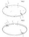
- Ein Ausführungsbeispiel der Erfindung wird anhand der rein schematischen Darstellungen nachfolgend näher erläutert. Dabei zeigt
- Fig. 1
- eine perspektivische Ansicht auf einen Schachtdeckel,
- Fig. 2
- eine Ansicht ähnlich
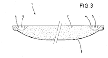
Fig. 1 , jedoch mit einer teilweise durchsichtig dargestellten Füllung, und - Fig. 3
- einen Querschnitt durch den Schachtdeckel der
Fig. 1 und 2 . - In den Zeichnungen ist mit 1 insgesamt ein Schachtdeckel bezeichnet, der im Wesentlichen aus Beton besteht, wobei der Beton eine Füllung 2 bildet, die in eine Kunststoffschale gegossen ist, welche einen Boden 3 des Schachtdeckels 1 bildet. Der Boden 3 ist dabei schalenförmig ausgestaltet und bildet nicht nur die Unterseite, sondern auch einen umlaufenden seitlichen Rand.
- In der Füllung 2 sind zwei Mulden 4 vorgesehen, die einander diametral gegenüberliegen und durch die sich jeweils ein Draht erstreckt, der eine Hebelasche 5 bildet.
- Wie insbesondere
Fig. 2 zeigt, verläuft jeder Draht etwa wellenförmig und ist mit seinen beiden Enden in der Füllung 2 verankert, während sich das Mittelteil dieses Drahtes aufwärts und durch die Mulde 4 erstreckt. Auf diese Weise wird eine vergleichsweise geringe Schichtdicke der Füllung 2 erzielt, da die beiden Enden des Drahtes von einer vergleichsweise dicken Schicht der Füllung 2 überdeckt sind und somit einen hervorragenden Halt in der Füllung 2 gegen Ausbrechen aufweisen, andererseits erstreckt sich das Mittelteil jedes Drahtes als Hebelasche 5 in einem großen Abstand höher als es dem tiefsten Grund der Mulde 4 entspricht, so dass die Hebelaschen 5 problemlos unterfasst werden können und dementsprechend der Schachtdeckel 1 problemlos gehandhabt werden kann. - Für die Herstellung eines Schachtdeckels 1 werden nur drei unterschiedliche Komponenten verwendet, nämlich erstens der Boden 3, in den dann zweitens die Füllung 2 eingefüllt wird, wobei ein Draht als Hebelasche 5 eingegossen und von der Füllung 2 umschlossen wird. Von diesen drei unterschiedlichen Komponenten wird der Draht bzw. die Hebelasche 5 in zweifacher Ausfertigung verwendet, aber herstellungstechnisch sind nur drei unterschiedliche Komponenten herzustellen, um den Schachtdeckel 1 zu schaffen. Der Beton der Füllung 2 ist dabei ein vergleichsweise einfacher und preisgünstiger Betonwerkstoff, der als rein mineralischer Beton ohne Polymerzusätze o. dgl. auskommt, keine Faserverstärkungen aufweist o. dgl., so dass er für die geforderte Festigkeit des Schachtdeckels 1 eine besonders wirtschaftliche Fertigung des Schachtdeckels ermöglicht.
Claims (7)
- Schachtdeckel,
mit einem schalenförmigen Boden,
und mit einer innerhalb dieses schalenförmigen Bodens angeordneten Füllung aus Beton,
dadurch gekennzeichnet, dass▪ der Boden (3) aus einem mit Glasfasern verstärkten, duroplastischen Kunststoff besteht,
eine zur Füllung (2) gerichtete rauhe Innenseite, sowie eine Schichtdicke von höchstens 5 mm aufweist,▪ der Beton, welcher die Füllung (2) bildet, als rein mineralischer Beton ausgestaltet ist,▪ zwischen dem Boden (3) und der Füllung (2) ein Haftvermittler vorgesehen ist,▪ in der Füllung (2) eine oder mehrere versenkt angeordnete Hebelaschen (5) vorgesehen sind,
wobei eine Hebelasche (5) aus einem Draht gebildet ist, dessen beiden Enden in der Füllung (2) verankert sind, und dessen Mittelteil sich durch eine in der Oberfläche der Füllung (2) vorgesehene Mulde (4) erstreckt,▪ und dass der Schachtdeckel (1) ausschließlich aus den vorgenannten Elementen gebildet ist. - Schachtdeckel nach Anspruch 1,
dadurch gekennzeichnet,
dass zwei Hebelaschen (5) vorgesehen sind, die einander - bezogen auf den Mittelpunkt des Schachtdeckels (1) - gegenüberliegen. - Schachtdeckel nach Anspruch 1 oder 2,
dadurch gekennzeichnet,
dass der eine Hebelasche (5) bildende Draht bogenförmig verläuft,
wobei er ein aufwärts gewölbt verlaufendes Mittelteil aufweist. - Schachtdeckel nach einem der vorhergehenden Ansprüche,
dadurch gekennzeichnet,
dass die Hebelasche (5) unbeweglich in der Füllung verankert ist. - Schachtdeckel nach einem der vorhergehenden Ansprüche,
dadurch gekennzeichnet,
dass der Kunststoff mit ungerichteten Fasermatten verstärkt ist. - Schachtdeckel nach einem der vorhergehenden Ansprüche,
dadurch gekennzeichnet,
dass der Schachtdeckel bis zu einer zulässigen Gewichtsbelastung von 5t belastbar ist. - Schachtdeckel nach einem der vorhergehenden Ansprüche,
dadurch gekennzeichnet,
dass der Schachtdeckel bis zu einer Berstkraft von 6t belastbar ist.
Priority Applications (1)
| Application Number | Priority Date | Filing Date | Title |
|---|---|---|---|
| PL12174664T PL2543773T3 (pl) | 2011-07-06 | 2012-07-02 | Pokrywa szybu |
Applications Claiming Priority (1)
| Application Number | Priority Date | Filing Date | Title |
|---|---|---|---|
| DE201110051611 DE102011051611A1 (de) | 2011-07-06 | 2011-07-06 | Herstellungsoptimierter Schachtdeckel |
Publications (2)
| Publication Number | Publication Date |
|---|---|
| EP2543773A1 EP2543773A1 (de) | 2013-01-09 |
| EP2543773B1 true EP2543773B1 (de) | 2015-06-17 |
Family
ID=46395538
Family Applications (1)
| Application Number | Title | Priority Date | Filing Date |
|---|---|---|---|
| EP12174664.8A Active EP2543773B1 (de) | 2011-07-06 | 2012-07-02 | Schachtdeckel |
Country Status (4)
| Country | Link |
|---|---|
| US (1) | US8454263B2 (de) |
| EP (1) | EP2543773B1 (de) |
| DE (1) | DE102011051611A1 (de) |
| PL (1) | PL2543773T3 (de) |
Families Citing this family (16)
| Publication number | Priority date | Publication date | Assignee | Title |
|---|---|---|---|---|
| US8727659B1 (en) * | 2013-03-08 | 2014-05-20 | EJ USA, Inc. | Manhole cover with insert |
| USD724758S1 (en) * | 2013-07-16 | 2015-03-17 | William J. Lumme, Jr. | Manhole leveling cover |
| US9303381B2 (en) * | 2013-12-09 | 2016-04-05 | John E Balogh | Handhole and manhole anti-theft insert |
| JP6228008B2 (ja) * | 2013-12-27 | 2017-11-08 | 未来工業株式会社 | マンホール蓋凹所の閉塞蓋、蓋体及び凹所閉塞マンホール蓋 |
| US10047493B2 (en) | 2014-09-05 | 2018-08-14 | Hubbell Incorporated | Hybrid utility cover |
| US10358285B2 (en) * | 2015-04-10 | 2019-07-23 | Channell Commercial Corporation | Thermoset polymer utility vault lid |
| ES2642935B1 (es) * | 2016-05-19 | 2018-09-13 | Manufacturas Y Transformados Ab, S.L. | Tapa para su uso en vías públicas |
| EP3472393B1 (de) * | 2016-06-20 | 2022-11-30 | Basf Se | Schachtabdeckung für schächte, kanalzugänge oder entwässerungsrinnen |
| WO2018067326A2 (en) | 2016-10-06 | 2018-04-12 | Hubbell Incorporated | Utility cover for use with automated metering equipment |
| US11221233B2 (en) | 2016-10-06 | 2022-01-11 | Hubbell Incorporated | Utility cover for use with automated metering equipment |
| US10240317B2 (en) * | 2016-10-10 | 2019-03-26 | Trumbull Manufacturing, Inc. | Cover assembly |
| US20190161936A1 (en) * | 2016-10-10 | 2019-05-30 | Trumbull Manufacturing, Inc. | Cover assembly |
| US11525235B2 (en) | 2016-12-12 | 2022-12-13 | Composite Access Products GP, LLC | Composite manhole cover with embedded detection |
| US20190309486A1 (en) * | 2018-04-10 | 2019-10-10 | Locke Solutions, Llc | Monolithic slotted drain |
| CN109707028A (zh) * | 2019-02-27 | 2019-05-03 | 西南交通大学 | 一种土木工程盖板 |
| ES1270700Y (es) * | 2021-05-19 | 2021-09-30 | Mas Juan Manuel Martinez | Proteccion colectiva y senalizacion de registros en edificacion y obra civil |
Family Cites Families (15)
| Publication number | Priority date | Publication date | Assignee | Title |
|---|---|---|---|---|
| US149246A (en) * | 1874-03-31 | Improvement in vault-covers | ||
| US783702A (en) * | 1903-06-10 | 1905-02-28 | David E Olds | Manhole-cover. |
| US4013374A (en) * | 1975-10-16 | 1977-03-22 | Passavant-Werke Michelbacher Hutte | Cover for manhole structures |
| GB2145444B (en) * | 1983-08-05 | 1988-04-07 | John Patrick Telford | Manhole chambers |
| DE3469447D1 (en) * | 1983-11-26 | 1988-03-31 | John Reginald Newton | Composite article |
| US4801483A (en) * | 1987-02-13 | 1989-01-31 | Power-Tel Products Group, Inc. | High strength, light weight structural composite and method of preparing same |
| US4974992A (en) * | 1988-10-07 | 1990-12-04 | Harter William M | Excavation closure |
| US5123776A (en) * | 1991-01-31 | 1992-06-23 | Advanced Drainage Systems, Inc. | Plastic fillable manhole cover with penetrating handles |
| DE29801640U1 (de) | 1998-01-31 | 1998-05-20 | Meyer, Heike, 10437 Berlin | Schachtabdeckung |
| USD428658S (en) * | 1999-10-06 | 2000-07-25 | Morrison Bros. Company | Manhole cover |
| USD428999S (en) * | 1999-10-06 | 2000-08-01 | Morrison Bros. Company | Manhole cover |
| US6393771B1 (en) * | 2000-02-10 | 2002-05-28 | Michael Alan Stetson | Cover for closing surface disposed utility access opening |
| US6682257B1 (en) * | 2002-03-07 | 2004-01-27 | Raymond Zappe | Cover apparatus for an access opening |
| US7537413B1 (en) * | 2007-01-07 | 2009-05-26 | Ricardo Brugos | Adjustable manhole cover apparatus |
| US7914227B2 (en) * | 2008-05-15 | 2011-03-29 | Energy Products, Llc | Thermally and electrically insulated composite manhole covers |
-
2011
- 2011-07-06 DE DE201110051611 patent/DE102011051611A1/de not_active Withdrawn
-
2012
- 2012-07-02 EP EP12174664.8A patent/EP2543773B1/de active Active
- 2012-07-02 PL PL12174664T patent/PL2543773T3/pl unknown
- 2012-07-06 US US13/542,772 patent/US8454263B2/en not_active Expired - Fee Related
Also Published As
| Publication number | Publication date |
|---|---|
| US8454263B2 (en) | 2013-06-04 |
| DE102011051611A1 (de) | 2013-01-10 |
| EP2543773A1 (de) | 2013-01-09 |
| PL2543773T3 (pl) | 2015-12-31 |
| US20130011194A1 (en) | 2013-01-10 |
Similar Documents
| Publication | Publication Date | Title |
|---|---|---|
| EP2543773B1 (de) | Schachtdeckel | |
| DE102015115968A1 (de) | Elastisches wasserdurchlässiges Bodengitter | |
| EP0576939B1 (de) | Aus Kunststoff bestehendes Mehrzweckbauteil | |
| DE102008019076A1 (de) | Gabione | |
| DE102011052311A1 (de) | Strukturelement | |
| EP2431533B1 (de) | Schachtdeckel | |
| EP4038240A1 (de) | Fundament für eine windkraftanlage | |
| DE202014008919U1 (de) | Füllkörper und Vorrichtung zum Zwischenspeichern von Sicker- und Regenwasser sowie dessen Verwendung | |
| DE202009004195U1 (de) | Bewehrungsvorrichtung zur Herstellung eines Fertigbauteils | |
| DE202018006645U1 (de) | Entwässerungsblöcke für Deiche oder in städtischen Gebieten | |
| DE202011003655U1 (de) | Schachtabdeckung aus Gußeisen | |
| DE102007051189B4 (de) | Ablaufeinrichtung | |
| DE102007020865A1 (de) | Gussfreundliche Schachtabdeckung mit dämpfender Einlage | |
| EP3369862B1 (de) | Rinnenelement zur bildung einer entwässerungsrinne | |
| DE102005017643B4 (de) | Geschlossene Hohlform zur Verwendung in einem Stein,Stein, Steinverbund | |
| DE2757465A1 (de) | Stuetzkoerper als teil einer zu bepflanzenden hangflaeche | |
| AT281896B (de) | Rasterfliese aus kunststoff | |
| EP0860550A2 (de) | Vorrichtung für die Anpflanzung von Bäumen und dergleichen | |
| EP2365138B1 (de) | Rahmen | |
| EP2767490B1 (de) | Kunststoff-Tank | |
| DE29917166U1 (de) | Abdeckvorrichtung für Kanäle, Entwässerungssysteme u.dgl. | |
| EP3318675B1 (de) | Muldenanordnung mit verlegehilfe | |
| DE102017112379A1 (de) | Doppelwandige Montagegrube aus Wandelementen | |
| DE29621349U1 (de) | Bodenbelagselement | |
| CH482073A (de) | Runder, befahrbarer Schachtdeckel |
Legal Events
| Date | Code | Title | Description |
|---|---|---|---|
| PUAI | Public reference made under article 153(3) epc to a published international application that has entered the european phase |
Free format text: ORIGINAL CODE: 0009012 |
|
| AK | Designated contracting states |
Kind code of ref document: A1 Designated state(s): AL AT BE BG CH CY CZ DE DK EE ES FI FR GB GR HR HU IE IS IT LI LT LU LV MC MK MT NL NO PL PT RO RS SE SI SK SM TR |
|
| AX | Request for extension of the european patent |
Extension state: BA ME |
|
| 17P | Request for examination filed |
Effective date: 20121213 |
|
| GRAP | Despatch of communication of intention to grant a patent |
Free format text: ORIGINAL CODE: EPIDOSNIGR1 |
|
| INTG | Intention to grant announced |
Effective date: 20150210 |
|
| GRAS | Grant fee paid |
Free format text: ORIGINAL CODE: EPIDOSNIGR3 |
|
| GRAA | (expected) grant |
Free format text: ORIGINAL CODE: 0009210 |
|
| AK | Designated contracting states |
Kind code of ref document: B1 Designated state(s): AL AT BE BG CH CY CZ DE DK EE ES FI FR GB GR HR HU IE IS IT LI LT LU LV MC MK MT NL NO PL PT RO RS SE SI SK SM TR |
|
| REG | Reference to a national code |
Ref country code: GB Ref legal event code: FG4D Free format text: NOT ENGLISH |
|
| REG | Reference to a national code |
Ref country code: CH Ref legal event code: EP |
|
| REG | Reference to a national code |
Ref country code: AT Ref legal event code: REF Ref document number: 732021 Country of ref document: AT Kind code of ref document: T Effective date: 20150715 |
|
| REG | Reference to a national code |
Ref country code: IE Ref legal event code: FG4D Free format text: LANGUAGE OF EP DOCUMENT: GERMAN |
|
| REG | Reference to a national code |
Ref country code: DE Ref legal event code: R096 Ref document number: 502012003459 Country of ref document: DE |
|
| PG25 | Lapsed in a contracting state [announced via postgrant information from national office to epo] |
Ref country code: HR Free format text: LAPSE BECAUSE OF FAILURE TO SUBMIT A TRANSLATION OF THE DESCRIPTION OR TO PAY THE FEE WITHIN THE PRESCRIBED TIME-LIMIT Effective date: 20150617 Ref country code: LT Free format text: LAPSE BECAUSE OF FAILURE TO SUBMIT A TRANSLATION OF THE DESCRIPTION OR TO PAY THE FEE WITHIN THE PRESCRIBED TIME-LIMIT Effective date: 20150617 Ref country code: FI Free format text: LAPSE BECAUSE OF FAILURE TO SUBMIT A TRANSLATION OF THE DESCRIPTION OR TO PAY THE FEE WITHIN THE PRESCRIBED TIME-LIMIT Effective date: 20150617 Ref country code: NO Free format text: LAPSE BECAUSE OF FAILURE TO SUBMIT A TRANSLATION OF THE DESCRIPTION OR TO PAY THE FEE WITHIN THE PRESCRIBED TIME-LIMIT Effective date: 20150917 |
|
| REG | Reference to a national code |
Ref country code: NL Ref legal event code: FP |
|
| REG | Reference to a national code |
Ref country code: LT Ref legal event code: MG4D |
|
| PG25 | Lapsed in a contracting state [announced via postgrant information from national office to epo] |
Ref country code: GR Free format text: LAPSE BECAUSE OF FAILURE TO SUBMIT A TRANSLATION OF THE DESCRIPTION OR TO PAY THE FEE WITHIN THE PRESCRIBED TIME-LIMIT Effective date: 20150918 Ref country code: BG Free format text: LAPSE BECAUSE OF FAILURE TO SUBMIT A TRANSLATION OF THE DESCRIPTION OR TO PAY THE FEE WITHIN THE PRESCRIBED TIME-LIMIT Effective date: 20150917 Ref country code: LV Free format text: LAPSE BECAUSE OF FAILURE TO SUBMIT A TRANSLATION OF THE DESCRIPTION OR TO PAY THE FEE WITHIN THE PRESCRIBED TIME-LIMIT Effective date: 20150617 Ref country code: RS Free format text: LAPSE BECAUSE OF FAILURE TO SUBMIT A TRANSLATION OF THE DESCRIPTION OR TO PAY THE FEE WITHIN THE PRESCRIBED TIME-LIMIT Effective date: 20150617 |
|
| REG | Reference to a national code |
Ref country code: RO Ref legal event code: EPE |
|
| REG | Reference to a national code |
Ref country code: FR Ref legal event code: PLFP Year of fee payment: 4 |
|
| REG | Reference to a national code |
Ref country code: PL Ref legal event code: T3 |
|
| PG25 | Lapsed in a contracting state [announced via postgrant information from national office to epo] |
Ref country code: EE Free format text: LAPSE BECAUSE OF FAILURE TO SUBMIT A TRANSLATION OF THE DESCRIPTION OR TO PAY THE FEE WITHIN THE PRESCRIBED TIME-LIMIT Effective date: 20150617 |
|
| PG25 | Lapsed in a contracting state [announced via postgrant information from national office to epo] |
Ref country code: PT Free format text: LAPSE BECAUSE OF FAILURE TO SUBMIT A TRANSLATION OF THE DESCRIPTION OR TO PAY THE FEE WITHIN THE PRESCRIBED TIME-LIMIT Effective date: 20151019 Ref country code: ES Free format text: LAPSE BECAUSE OF FAILURE TO SUBMIT A TRANSLATION OF THE DESCRIPTION OR TO PAY THE FEE WITHIN THE PRESCRIBED TIME-LIMIT Effective date: 20150617 Ref country code: SK Free format text: LAPSE BECAUSE OF FAILURE TO SUBMIT A TRANSLATION OF THE DESCRIPTION OR TO PAY THE FEE WITHIN THE PRESCRIBED TIME-LIMIT Effective date: 20150617 Ref country code: IS Free format text: LAPSE BECAUSE OF FAILURE TO SUBMIT A TRANSLATION OF THE DESCRIPTION OR TO PAY THE FEE WITHIN THE PRESCRIBED TIME-LIMIT Effective date: 20151017 |
|
| PGFP | Annual fee paid to national office [announced via postgrant information from national office to epo] |
Ref country code: FR Payment date: 20151224 Year of fee payment: 4 Ref country code: PL Payment date: 20151228 Year of fee payment: 4 |
|
| REG | Reference to a national code |
Ref country code: CH Ref legal event code: PL |
|
| REG | Reference to a national code |
Ref country code: DE Ref legal event code: R097 Ref document number: 502012003459 Country of ref document: DE |
|
| PG25 | Lapsed in a contracting state [announced via postgrant information from national office to epo] |
Ref country code: MC Free format text: LAPSE BECAUSE OF FAILURE TO SUBMIT A TRANSLATION OF THE DESCRIPTION OR TO PAY THE FEE WITHIN THE PRESCRIBED TIME-LIMIT Effective date: 20150617 |
|
| REG | Reference to a national code |
Ref country code: IE Ref legal event code: MM4A |
|
| PLBE | No opposition filed within time limit |
Free format text: ORIGINAL CODE: 0009261 |
|
| STAA | Information on the status of an ep patent application or granted ep patent |
Free format text: STATUS: NO OPPOSITION FILED WITHIN TIME LIMIT |
|
| PG25 | Lapsed in a contracting state [announced via postgrant information from national office to epo] |
Ref country code: LI Free format text: LAPSE BECAUSE OF NON-PAYMENT OF DUE FEES Effective date: 20150731 Ref country code: IT Free format text: LAPSE BECAUSE OF FAILURE TO SUBMIT A TRANSLATION OF THE DESCRIPTION OR TO PAY THE FEE WITHIN THE PRESCRIBED TIME-LIMIT Effective date: 20150617 Ref country code: DK Free format text: LAPSE BECAUSE OF FAILURE TO SUBMIT A TRANSLATION OF THE DESCRIPTION OR TO PAY THE FEE WITHIN THE PRESCRIBED TIME-LIMIT Effective date: 20150617 Ref country code: CH Free format text: LAPSE BECAUSE OF NON-PAYMENT OF DUE FEES Effective date: 20150731 |
|
| 26N | No opposition filed |
Effective date: 20160318 |
|
| PG25 | Lapsed in a contracting state [announced via postgrant information from national office to epo] |
Ref country code: IE Free format text: LAPSE BECAUSE OF NON-PAYMENT OF DUE FEES Effective date: 20150702 |
|
| PG25 | Lapsed in a contracting state [announced via postgrant information from national office to epo] |
Ref country code: SI Free format text: LAPSE BECAUSE OF FAILURE TO SUBMIT A TRANSLATION OF THE DESCRIPTION OR TO PAY THE FEE WITHIN THE PRESCRIBED TIME-LIMIT Effective date: 20150617 |
|
| GBPC | Gb: european patent ceased through non-payment of renewal fee |
Effective date: 20160702 |
|
| PG25 | Lapsed in a contracting state [announced via postgrant information from national office to epo] |
Ref country code: MT Free format text: LAPSE BECAUSE OF FAILURE TO SUBMIT A TRANSLATION OF THE DESCRIPTION OR TO PAY THE FEE WITHIN THE PRESCRIBED TIME-LIMIT Effective date: 20150617 |
|
| PG25 | Lapsed in a contracting state [announced via postgrant information from national office to epo] |
Ref country code: FR Free format text: LAPSE BECAUSE OF NON-PAYMENT OF DUE FEES Effective date: 20160801 |
|
| REG | Reference to a national code |
Ref country code: FR Ref legal event code: ST Effective date: 20170331 |
|
| PG25 | Lapsed in a contracting state [announced via postgrant information from national office to epo] |
Ref country code: GB Free format text: LAPSE BECAUSE OF NON-PAYMENT OF DUE FEES Effective date: 20160702 Ref country code: SM Free format text: LAPSE BECAUSE OF FAILURE TO SUBMIT A TRANSLATION OF THE DESCRIPTION OR TO PAY THE FEE WITHIN THE PRESCRIBED TIME-LIMIT Effective date: 20150617 Ref country code: HU Free format text: LAPSE BECAUSE OF FAILURE TO SUBMIT A TRANSLATION OF THE DESCRIPTION OR TO PAY THE FEE WITHIN THE PRESCRIBED TIME-LIMIT; INVALID AB INITIO Effective date: 20120702 |
|
| PG25 | Lapsed in a contracting state [announced via postgrant information from national office to epo] |
Ref country code: SE Free format text: LAPSE BECAUSE OF FAILURE TO SUBMIT A TRANSLATION OF THE DESCRIPTION OR TO PAY THE FEE WITHIN THE PRESCRIBED TIME-LIMIT Effective date: 20150617 Ref country code: CY Free format text: LAPSE BECAUSE OF FAILURE TO SUBMIT A TRANSLATION OF THE DESCRIPTION OR TO PAY THE FEE WITHIN THE PRESCRIBED TIME-LIMIT Effective date: 20150617 |
|
| PG25 | Lapsed in a contracting state [announced via postgrant information from national office to epo] |
Ref country code: BE Free format text: LAPSE BECAUSE OF NON-PAYMENT OF DUE FEES Effective date: 20150731 |
|
| PG25 | Lapsed in a contracting state [announced via postgrant information from national office to epo] |
Ref country code: LU Free format text: LAPSE BECAUSE OF NON-PAYMENT OF DUE FEES Effective date: 20150702 |
|
| PG25 | Lapsed in a contracting state [announced via postgrant information from national office to epo] |
Ref country code: PL Free format text: LAPSE BECAUSE OF NON-PAYMENT OF DUE FEES Effective date: 20160702 |
|
| PG25 | Lapsed in a contracting state [announced via postgrant information from national office to epo] |
Ref country code: MK Free format text: LAPSE BECAUSE OF FAILURE TO SUBMIT A TRANSLATION OF THE DESCRIPTION OR TO PAY THE FEE WITHIN THE PRESCRIBED TIME-LIMIT Effective date: 20150617 |
|
| REG | Reference to a national code |
Ref country code: AT Ref legal event code: MM01 Ref document number: 732021 Country of ref document: AT Kind code of ref document: T Effective date: 20170702 |
|
| PG25 | Lapsed in a contracting state [announced via postgrant information from national office to epo] |
Ref country code: AL Free format text: LAPSE BECAUSE OF FAILURE TO SUBMIT A TRANSLATION OF THE DESCRIPTION OR TO PAY THE FEE WITHIN THE PRESCRIBED TIME-LIMIT Effective date: 20150617 |
|
| PG25 | Lapsed in a contracting state [announced via postgrant information from national office to epo] |
Ref country code: AT Free format text: LAPSE BECAUSE OF NON-PAYMENT OF DUE FEES Effective date: 20170702 |
|
| PG25 | Lapsed in a contracting state [announced via postgrant information from national office to epo] |
Ref country code: TR Free format text: LAPSE BECAUSE OF NON-PAYMENT OF DUE FEES Effective date: 20160702 |
|
| PGFP | Annual fee paid to national office [announced via postgrant information from national office to epo] |
Ref country code: CZ Payment date: 20230621 Year of fee payment: 12 |
|
| PGFP | Annual fee paid to national office [announced via postgrant information from national office to epo] |
Ref country code: NL Payment date: 20230720 Year of fee payment: 12 |
|
| REG | Reference to a national code |
Ref country code: DE Ref legal event code: R082 Ref document number: 502012003459 Country of ref document: DE Representative=s name: PATENTANWAELTE OLBRICHT, BUCHHOLD, KEULERTZ PA, DE |
|
| PG25 | Lapsed in a contracting state [announced via postgrant information from national office to epo] |
Ref country code: CZ Free format text: LAPSE BECAUSE OF NON-PAYMENT OF DUE FEES Effective date: 20240702 |
|
| PG25 | Lapsed in a contracting state [announced via postgrant information from national office to epo] |
Ref country code: CZ Free format text: LAPSE BECAUSE OF NON-PAYMENT OF DUE FEES Effective date: 20240702 |
|
| REG | Reference to a national code |
Ref country code: NL Ref legal event code: MM Effective date: 20240801 |
|
| PG25 | Lapsed in a contracting state [announced via postgrant information from national office to epo] |
Ref country code: NL Free format text: LAPSE BECAUSE OF NON-PAYMENT OF DUE FEES Effective date: 20240801 |
|
| PGFP | Annual fee paid to national office [announced via postgrant information from national office to epo] |
Ref country code: RO Payment date: 20250627 Year of fee payment: 14 |
|
| PGFP | Annual fee paid to national office [announced via postgrant information from national office to epo] |
Ref country code: DE Payment date: 20250731 Year of fee payment: 14 |