EP2543799A2 - Türschliessvorrichtung - Google Patents
Türschliessvorrichtung Download PDFInfo
- Publication number
- EP2543799A2 EP2543799A2 EP11460013A EP11460013A EP2543799A2 EP 2543799 A2 EP2543799 A2 EP 2543799A2 EP 11460013 A EP11460013 A EP 11460013A EP 11460013 A EP11460013 A EP 11460013A EP 2543799 A2 EP2543799 A2 EP 2543799A2
- Authority
- EP
- European Patent Office
- Prior art keywords
- door
- housing
- tube
- lock
- housings
- Prior art date
- Legal status (The legal status is an assumption and is not a legal conclusion. Google has not performed a legal analysis and makes no representation as to the accuracy of the status listed.)
- Withdrawn
Links
- 239000011521 glass Substances 0.000 claims abstract description 15
- 239000013013 elastic material Substances 0.000 description 2
- 238000009434 installation Methods 0.000 description 2
- 239000000463 material Substances 0.000 description 2
- 125000006850 spacer group Chemical group 0.000 description 2
Images

Classifications
-
- E—FIXED CONSTRUCTIONS
- E05—LOCKS; KEYS; WINDOW OR DOOR FITTINGS; SAFES
- E05B—LOCKS; ACCESSORIES THEREFOR; HANDCUFFS
- E05B65/00—Locks or fastenings for special use
- E05B65/0025—Locks or fastenings for special use for glass wings
-
- E—FIXED CONSTRUCTIONS
- E05—LOCKS; KEYS; WINDOW OR DOOR FITTINGS; SAFES
- E05B—LOCKS; ACCESSORIES THEREFOR; HANDCUFFS
- E05B1/00—Knobs or handles for wings; Knobs, handles, or press buttons for locks or latches on wings
- E05B1/0015—Knobs or handles which do not operate the bolt or lock, e.g. non-movable; Mounting thereof
-
- E—FIXED CONSTRUCTIONS
- E05—LOCKS; KEYS; WINDOW OR DOOR FITTINGS; SAFES
- E05B—LOCKS; ACCESSORIES THEREFOR; HANDCUFFS
- E05B9/00—Lock casings or latch-mechanism casings ; Fastening locks or fasteners or parts thereof to the wing
- E05B9/08—Fastening locks or fasteners or parts thereof, e.g. the casings of latch-bolt locks or cylinder locks to the wing
- E05B9/084—Fastening of lock cylinders, plugs or cores
Definitions
- the subject of the invention is a door closing device, in particular for glass doors, using lock cylinders.
- EP 1 026 345 A1 A closing device for glass doors is also known in which a sliding bolt attached to a door side is used, which is actuated by the use of the lock on at least one side of the door.
- the door-closing device acting on one side consists of a tube which extends over the whole glass door height.
- the pipe is mounted with a distance from glass door.
- the pipe attachment to the door is successful using at least two connecting elements as well as the housing with the lock installed therein.
- the fasteners are located near the lower and upper door edges and the housing with the lock between the two fasteners.
- Inside the pipe there is a sliding bolt.
- the door is equipped with a rod serving as a door handle.
- the rod has a length almost equal to that of the tube and is spaced from the glass door by the spacers and housing.
- the spacer elements of the rod are connected to pipe fasteners and the rod body with the tubular body.
- the purpose of the invention is to develop a locking device, the installation of which would be easier and the disassembly of the device more difficult.
- the door closing device includes pipes on both sides of the glass door, which are mounted at a distance from the glass door.
- the tube is advantageously mounted only on one side of the door at a distance.
- Pipes are door handles.
- Within at least one tube is a sliding bolt coupled with the lock cylinder factory.
- the pipes are fastened to the door by means of at least one connecting element and the lock cylinder housing.
- the roller-shaped housing has two parallel, adapted to the outer tube shape holes through which the tube passes.
- the tube has two parallel openings for receiving the lock cylinder.
- the lock cylinder passes through holes adapted thereto in the upper and in the lower housing part.
- the lower housing part has at least two mounting holes on.
- the mounting holes of the housing are advantageously provided only on one side of the door with thread.
- washers made of an elastic material to prevent excessive tension in the door material.
- the mounting screws hold the two housings together through the washers and the opening in the glass door.
- the fastening screws advantageously connect the housing to the blanking plate through the washers and the glass door opening for only one pipe.
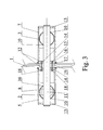
- the object of the invention is apparent from the figure. It represents the Fig. 1 the locking device in front view and the Fig. 2 the lock cylinder housing in longitudinal section.
- the door closing device has on both sides of the glass door 1 tubes 2 and 3, which serve as door handles.
- the tube 2 is mounted on one and the tube 3 on the other side of the door at a distance from the glass door.
- Within the tube 2 is a sliding bolt with the lock cylinder factory.
- the tube 2 is fastened to the door 1 by means of the connecting element 4 and the housing 5, and the tube 3 is fastened to the door 1 on the basis of connecting element 6 and of housing 7.
- the roller-shaped housing 5 and 7 have on their side surfaces 8 in parallel each a hole 9 with a the outer contour of the tubes 2 and 3 adapted shape. Through the holes 9 of the housing 5, the tube 2 and through the holes 9 of the housing 7, the tube 3 passes.
- the tubes 2 and 3 At the connection points of the tube 2 to the housing 7 and the tube 3 to the housing 7, the tubes 2 and 3, two parallel holes 10, in which the lock cylinder 11 is mounted.
- the lock cylinder 11 passes through the holes 12 adapted thereto respectively in the upper part 13 and lower part 14 of the housings 5 and 7.
- the lower parts 13 of the housing 5 and 7 also have two mounting holes 15.
- the mounting holes I 5 of the housing 7 are threaded 16 provided.
- the door 1 are washers of an elastic material to prevent excessive stresses in the door material.
- fastening screws 18 are attached, which connect the housing 5 and 7 through the washers and the opening 19 in the door 1 with each other.
- Example 11 The device differs from that of Example 1 in that it has the tube 2 only on a door side which is mounted at a distance from the door 1.
- Example III The device differs from that of Example 1 in that there are sliding bolt within the tube 2 and the tube 3.
Landscapes
- Window Of Vehicle (AREA)
Abstract
Description
- Der Gegenstand der Erfindung ist eine Türschließvorrichtung insbesondere für Glastüren unter Anwendung von Schlosszylinder.
- Von der Erfindungsbeschreibung
EP 1 026 345 A1 her ist auch eine Schließvorrichtung für Glastüren bekannt, bei der ein auf einer Türseite angebrachter Schubriegel eingesetzt ist, welcher mindestens auf einer Seite der Tür durch die Schlossnutzung betätigt wird. Die auf einer Seite wirkende Türschließvorrichtung besteht aus einem Rohr, welches sich über die ganze Glastürhöhe erstreckt. Das Rohr ist mit einem Abstand von Glastür angebracht. Die Rohrbefestigung an die Tür erfolg unter Einsatz von mindestens zwei Verbindungselementen sowie vom Gehäuse mit dem darin eingebauten Schloss. Die Verbindungselemente sind in der Nähe der unteren und der oberen Türkante und das Gehäuse mit dem Schloss zwischen den beiden Verbindungselementen angebracht. Im Rohrinneren befindet sich ein Schubriegel. Auf der anderen Seite ist die Tür mit einem als Türgriff dienenden Stab ausgestattet. Der Stab hat eine beinahe der des Rohres gleiche Länge und ist durch die Distanzelemente und das Gehäuse in einem Abstand von der Glastür gehalten. Die Distanzelemente des Stabes sind mit Rohrbefestigungselementen und der Stabkörper mit dem Rohrkörper verbunden. - Der Zweck der Erfindung besteht darin, eine Schließvorrichtung zu entwickeln, deren Einbau leichter und die Zerlegung der Vorrichtung schwieriger wäre.
- Die Türschließvorrichtung gemäß Erfindung enthält Rohre auf beiden Seiten der Glastür, die in einem Abstand von der Glastür angebracht sind. Das Rohr ist vorteilhaft nur auf einer Türseite in einem Abstand angebracht. Rohre sind Türgriffe. Innerhalb mindestens eines Rohres befindet sich ein Schubriegel verkoppelt mit dem Schlosszylinderwerk. Die Rohre sind an die Tür anhand von mindestens einem Verbindungselement und dem Schlosszylindergehäuse befestigt. Das walzenförmige Gehäuse weist zwei parallele, der Rohraußenform angepasste Löcher auf, durch welche das Rohr hindurchgeht. An der Verbindungsstelle des Rohres mit dem Gehäuse besitzt das Rohr zwei parallele Öffnungen für die Aufnahme des Schlosszylinders. Gleichzeitig geht der Schlosszylinder durch daran angepasste Löcher im oberen und im unteren Gehäuseteil hindurch. Außer von einem, dem Zylinderschloss angepassten Loch weist das Gehäuseunterteil mindestens zwei Befestigungslöcher auf. Die Befestigungslöcher des Gehäuses sind vorteilhaft nur auf einer Türseite mit Gewinde versehen. Zwischen den Gehäusen und der Glastür befinden sich Unterlegscheiben aus einem elastischen Stoff zur Verhinderung übermäßiger Spannungen im Türmaterial. In den Befestigungslöchern des Gehäuses sind Befestigungsschrauben angebracht. Die Befestigungsschrauben halten die beiden Gehäuse durch die Unterlegscheiben und die Öffnung in der Glastür zusammen. Die Befestigungsschrauben verbinden das Gehäuse mit der Blindplatte durch die Unterlegscheiben und die Glastüröffnung vorteilhaft für nur ein Rohr.
- Durch den Einsatz in der Vorrichtung eines Schlosszylinders, der mit Rohrdurchlasslöchern versehen ist, wird eine schnellere und leichtere Montage der Vorrichtung an die Tür ermöglicht. Gleichzeitig bleibt die Befestigung dieser Gehäuse an die Tür dadurch unsichtbar, dass die Befestigungslöcher im Unterteil des Schlosszylinders angeordnet sind, somit wird auch die Zerlegung der Schließvorrichtung von außen erschwert sein.
- Der Gegenstand der Erfindung ist aus der Abbildung ersichtlich. Dabei stellt die
Fig. 1 die Schließvorrichtung in Frontansicht und dieFig. 2 das Schlosszylindergehäuse im Längsschnitt dar. - Beispiel 1. Die Türschließvorrichtung besitzt auf beiden Seiten der Glastür 1 Rohre 2 und 3, die als Türgriffe dienen. Das Rohr 2 ist auf einer und das Rohr 3 auf der anderen Seite der Tür und zwar in einem Abstand von der Glastür angebracht. Innerhalb der Rohres 2 befindet sich ein Schubriegel mit dem Schlosszylinderwerk. Das Rohr 2 ist anhand vom Verbindungselement 4 und vom Gehäuse 5 an die Tür 1 befestigt und das Rohr 3 ist anhand von Verbindungselement 6 und von Gehäuse 7 an die Tür 1 befestigt. Die walzenförmigen Gehäuse 5 und 7 weisen auf ihren Seitenflächen 8 parallel je ein Loch 9 mit einer dem Außenumriss der Rohre 2 und 3 angepassten Form auf. Durch die Löcher 9 des Gehäuses 5 geht das Rohr 2 und durch die Löcher 9 des Gehäuses 7 das Rohr 3 hindurch. An der Anschlussstellen des Rohres 2 an das Gehäuse 7 und des Rohres 3 an das Gehäuse 7 weisen die Rohre 2 und 3 zwei parallele Löcher 10 auf, in denen der Schlosszylinder 11 angebracht ist. Gleichzeitig geht der Schlosszylinder 11 durch die daran angepassten Löcher 12 jeweils im Oberteil 13 und Unterteil 14 der Gehäuse 5 und 7 hindurch. Neben den dem Schlosszylinder 11 angepassten Löchern 12 besitzen die Unterteile 13 der Gehäuse 5 und 7 auch zwei Befestigungslöcher 15. Die Befestigungslöcher I 5 des Gehäuses 7 sind mit Gewinde 16 versehen. Zwischen einerseits den Gehäusen 5 und 7 und andererseits der Tür 1 befinden sich Unterlegscheiben aus einem elastischen Stoff, um übermäßige Spannungen im Türmaterial zu verhindern.
- In Befestigungslöchern 15 der Gehäuse 5 und 7 sind Befestigungsschrauben 18 angebracht, die die Gehäuse 5 und 7 durch die Unterlegscheiben und die Öffnung 19 in der Tür 1 miteinander verbinden.
- Beispiel 11. Die Vorrichtung unterscheidet sich von der nach Beispiel 1 dadurch, dass sie das Rohr 2 nur auf einer Türseite besitzt, welches in einem Abstand von der Tür 1 angebracht ist. Die Befestigungsschrauben 18 dagegen verbinden das Gehäuse 5 durch die Unterlegscheiben 17 und das Loch 19 an der Tür 1 mit der Blindplatte 10.
- Beispiel III. Die Vorrichtung unterscheidet sich von der nach Beispiel 1 dadurch, dass sich Schubriegel innerhalb des Rohres 2 und des Rohres 3 befinden.
Claims (3)
- Türschließvorrichtung mit in einem Abstand von der Glastür anhand von Verbindungselementen und Gehäusen angebrachten Rohren, in deren Inneren sich jeweils ein mit dem Schlosswerk und dem Schubriegel verkoppelter Schlosszylinder befindet, die insgesamt innerhalb des Rohres befestigt sind, einschließlich zwischen den Gehäusen und der Glastür befindlicher Unterlegscheiben, wobei die Gehäuse jeweils eine Walzenform mit zwei parallelen, der Rohraußenform angepassten Öffnungen besitzen und die Rohre an ihren Gehäuseanschlussstellen jeweils zwei parallele Öffnungen aufweisen, in denen der Schlosszylinder angebracht ist, dadurch gekennzeichnet, dass der Schlosszylinder (11) durch das daran angepasste Loch (12) im Oberteil (13) und im Unterteil (14) der Gehäuse (5 und 7) hindurchgeht und die Unterteile (13) der Gehäuse (5 und 7) neben dem an den Zylinderschloss angepassten Loch (12) auch zwei Befestigungslöcher (15) für Befestigungsschrauben (18) besitzen.
- Vorrichtung nach Anspruch 1, dadurch gekennzeichnet, dass die Befestigungslöcher (15) des Gehäuses (7) mit Gewinde (16) versehen sind.
- Vorrichtung nach Anspruch 1, dadurch gekennzeichnet, dass die Befestigungsschrauben (18) das Gehäuse (5) mit dem hindurchgehendem Rohr (2) mit einer Blindplatte (20) durch die Unterlegscheiben (17) und das Loch (19) in der Tür (1) verbinden.
Applications Claiming Priority (1)
| Application Number | Priority Date | Filing Date | Title |
|---|---|---|---|
| PL39083310 | 2010-03-26 |
Publications (1)
| Publication Number | Publication Date |
|---|---|
| EP2543799A2 true EP2543799A2 (de) | 2013-01-09 |
Family
ID=44118539
Family Applications (1)
| Application Number | Title | Priority Date | Filing Date |
|---|---|---|---|
| EP11460013A Withdrawn EP2543799A2 (de) | 2010-03-26 | 2011-03-23 | Türschliessvorrichtung |
Country Status (1)
| Country | Link |
|---|---|
| EP (1) | EP2543799A2 (de) |
Cited By (1)
| Publication number | Priority date | Publication date | Assignee | Title |
|---|---|---|---|---|
| US9003843B2 (en) | 2013-06-14 | 2015-04-14 | Gregory Header | Integrated door operator hardware |
Citations (1)
| Publication number | Priority date | Publication date | Assignee | Title |
|---|---|---|---|---|
| EP1026345A1 (de) | 1999-02-05 | 2000-08-09 | Valeo Securite Habitacle | Schloss mit einem System für elektrische Öffnungshilfe eines Kraftfahrzeugflügels |
-
2011
- 2011-03-23 EP EP11460013A patent/EP2543799A2/de not_active Withdrawn
Patent Citations (1)
| Publication number | Priority date | Publication date | Assignee | Title |
|---|---|---|---|---|
| EP1026345A1 (de) | 1999-02-05 | 2000-08-09 | Valeo Securite Habitacle | Schloss mit einem System für elektrische Öffnungshilfe eines Kraftfahrzeugflügels |
Cited By (2)
| Publication number | Priority date | Publication date | Assignee | Title |
|---|---|---|---|---|
| US9003843B2 (en) | 2013-06-14 | 2015-04-14 | Gregory Header | Integrated door operator hardware |
| US9303430B2 (en) | 2013-06-14 | 2016-04-05 | Gregory Header | Integrated door operator hardware with recessed handle |
Similar Documents
| Publication | Publication Date | Title |
|---|---|---|
| EP3445935B1 (de) | Schiebetüranlage | |
| EP1849952A2 (de) | Montagesystem für Fenster und dergleichen | |
| EP2876222A1 (de) | Verdeckte Befestigungsvorrichtung für ein wandbefestigtes WC | |
| DE102009050689A1 (de) | Schutzzaun | |
| EP1317594B1 (de) | Türbetätigungsaggregat für insbesondere kraftfahrzeuge | |
| DE102006016045A1 (de) | Vorrichtung zur lösbaren Halterung von einem Flächenelement und deren Verwendung | |
| EP1243739A1 (de) | Punkthalter für Platten | |
| DE102004005422A1 (de) | Montagekonsole für Fenster oder dergleichen | |
| EP2543799A2 (de) | Türschliessvorrichtung | |
| EP3095365B1 (de) | Duschabtrennung mit schiebetüre und führungselement | |
| DE102016114668B3 (de) | Isoliersteg und Brandschutzkonstruktion mit Isoliersteg | |
| EP3444486B1 (de) | Befestigungseinheit für zaunteile | |
| DE102009011179A1 (de) | Vorrichtung zum Haltern eines Heizkörpers | |
| DE102017108090A1 (de) | Haltesystem zum Halten eines Objekts | |
| DE202005010512U1 (de) | Halterung zur Einspannung einer Glasscheibe | |
| AT518633B1 (de) | Bausatztür | |
| EP2959812B1 (de) | Anordnung zum verbinden zweier profilschienen | |
| DE202009002137U1 (de) | Pfostenträger | |
| DE202013105729U1 (de) | Befestigungsvorrichtung zum Überbrücken einer nicht tragenden Wandschicht | |
| AT515483B1 (de) | Vorrichtung zur schwenkbaren Anbindung eines plattenartigen Absperrelements an ein feststehendes Bauelement | |
| DE102011112036A1 (de) | Befestigungsvorrichtung | |
| DE102007061781A1 (de) | Befestigungsvorrichtung für zwischen Pfosten anzuordnende Zaun- oder Sicherschutzelemente | |
| EP3269903A1 (de) | Rosettengarnitur für drücker bei türen oder fenstern | |
| EP3146877A1 (de) | Duschkabine | |
| DE102012005442A1 (de) | Vorrichtung und Verfahren zur Montage einer Türzarge in einer Wandöffnung |
Legal Events
| Date | Code | Title | Description |
|---|---|---|---|
| PUAI | Public reference made under article 153(3) epc to a published international application that has entered the european phase |
Free format text: ORIGINAL CODE: 0009012 |
|
| AK | Designated contracting states |
Kind code of ref document: A2 Designated state(s): AL AT BE BG CH CY CZ DE DK EE ES FI FR GB GR HR HU IE IS IT LI LT LU LV MC MK MT NL NO PL PT RO RS SE SI SK SM TR |
|
| AX | Request for extension of the european patent |
Extension state: BA ME |
|
| PUAJ | Public notification under rule 129 epc |
Free format text: ORIGINAL CODE: 0009425 |
|
| 32PN | Public notification |
Free format text: FESTSTELLUNG EINES RECHTSVERLUSTS NACH REGEL 112(1) EPUE (EPA FORM 2524 VOM 29/10/2013) |
|
| STAA | Information on the status of an ep patent application or granted ep patent |
Free format text: STATUS: THE APPLICATION IS DEEMED TO BE WITHDRAWN |
|
| 18D | Application deemed to be withdrawn |
Effective date: 20131001 |