EP2543843A2 - Procédé de réglage d'une pression d'admission d'un moteur à combustion interne - Google Patents
Procédé de réglage d'une pression d'admission d'un moteur à combustion interne Download PDFInfo
- Publication number
- EP2543843A2 EP2543843A2 EP12166761A EP12166761A EP2543843A2 EP 2543843 A2 EP2543843 A2 EP 2543843A2 EP 12166761 A EP12166761 A EP 12166761A EP 12166761 A EP12166761 A EP 12166761A EP 2543843 A2 EP2543843 A2 EP 2543843A2
- Authority
- EP
- European Patent Office
- Prior art keywords
- engine
- channel
- internal combustion
- combustion engine
- speed
- Prior art date
- Legal status (The legal status is an assumption and is not a legal conclusion. Google has not performed a legal analysis and makes no representation as to the accuracy of the status listed.)
- Granted
Links
Images

Classifications
-
- F—MECHANICAL ENGINEERING; LIGHTING; HEATING; WEAPONS; BLASTING
- F02—COMBUSTION ENGINES; HOT-GAS OR COMBUSTION-PRODUCT ENGINE PLANTS
- F02B—INTERNAL-COMBUSTION PISTON ENGINES; COMBUSTION ENGINES IN GENERAL
- F02B33/00—Engines characterised by provision of pumps for charging or scavenging
- F02B33/32—Engines with pumps other than of reciprocating-piston type
- F02B33/42—Engines with pumps other than of reciprocating-piston type with driven apparatus for immediate conversion of combustion gas pressure into pressure of fresh charge, e.g. with cell-type pressure exchangers
-
- F—MECHANICAL ENGINEERING; LIGHTING; HEATING; WEAPONS; BLASTING
- F04—POSITIVE - DISPLACEMENT MACHINES FOR LIQUIDS; PUMPS FOR LIQUIDS OR ELASTIC FLUIDS
- F04F—PUMPING OF FLUID BY DIRECT CONTACT OF ANOTHER FLUID OR BY USING INERTIA OF FLUID TO BE PUMPED; SIPHONS
- F04F13/00—Pressure exchangers
Definitions
- the present invention relates to a method for adjusting a boost pressure of an internal combustion engine according to the features in the preamble of patent claim 1.
- a method for operating an internal combustion engine in which fresh air is compressed by a pressure wave supercharger, wherein at least one operating parameter of the pressure wave supercharger, depending on at least one actual operating variable of the internal combustion engine is controlled or regulated.
- the method disclosed therein means a departure from the previous rigid and essentially uncontrolled or uncontrolled operating concepts of pressure wave loaders.
- a pressure wave supercharger arrangement wherein an inflow to a gas pocket is branched off from an exhaust gas supply channel and this inflow is controlled in dependence of the boost pressure via a gas pocket valve.
- the gas pocket valve itself is controlled via a control line.
- the gas pocket inflow is thereby realized by avoiding gas blow-off from the high-pressure duct into the atmosphere at standstill and in emergency operation of the internal combustion engine by opening the gas pocket inflow by means of spring means.
- a pressure wave supercharger arrangement is known in which a rotatable cold gas housing is arranged to improve the performance of the pressure wave supercharger and the internal combustion engine to each other.
- the rotatable cold gas housing is adjusted during operation of the pressure wave supercharger to improve the operation of the pressure wave supercharger over the entire map range of the internal combustion engine.
- thermodynamic state variables Due to the pressure differences between the intake tract and the exhaust gas tract, a gas-dynamic process is formed in the rotor cells of the pressure wave supercharger itself, which produces a virtually infinite number of thermodynamic state variables. Since these are often only calculable through very long and very complex numerical equations, a detailed modeling of a pressure wave loader, which could be implemented on a control unit, is not possible with today's CAE methods.
- Object of the present invention is therefore to provide a method for controlling and regulating a pressure wave supercharger, which optimizes the emission behavior, the response, the durability and the efficiency of a pressure wave supercharger for an internal combustion engine while allowing a largely independent of external influences series use.
- the inventive method for adjusting a boost pressure of an internal combustion engine wherein the boost pressure is constructed by a pressure wave supercharger having a cell rotor and a cell rotor housing and the pressure wave supercharger a channel 1 for sucking fresh air, a channel 2 for discharging the compressed fresh air, a channel. 3 for supplying exhaust gas and a channel 4 for discharging exhaust gas are connected and the pressure wave supercharger has a cold gas housing, are connected to the channel 1 and 2, and a gas pocket valve, which is arranged in the region of the channel 3, characterized by, a position of the actuating element is set and / or regulated as a function of a difference between the actual value and the nominal value of the gas pocket valve position.
- the adjusting element is a rotatable housing, an adjusting element, an edge slider or a control roller which variably change the inlet and outlet openings via a geometric offset of channel 3 and channel 4 to channel 1 and channel 2 can.
- the adjusting element is arranged in the context of the invention on the cold gas side of the pressure wave supercharger. However, it can also be arranged on the hot gas side.
- the gas pocket valve which is arranged in the region of channel 3, further comprises a blow-by valve which regulates the gas flow rate in a channel 3 '.
- the channel 3 ' adjacent to channel 3 and also leads directly into the rotor cell of the cell rotor. Via the gas pocket valve, a variable opening from 0 to 100% of the channel 3 'is possible.
- the gas pocket valve can also form a direct bypass between channel 3 and channel 4 in the context of the invention. Also can be variably controlled via the gas pocket valve then the opening of the bypass from channel 3 to channel 4.
- the method according to the invention therefore offers a solution for optimum, dynamic adjustment of the engine operating state on the basis of energy changes which are present in channel 3.
- a regulation and control of the boost pressure setpoint takes place via the gas pocket valve position.
- the change in position of the gas pocket valve generates an energy pulse in the channel 3 of the pressure wave supercharger.
- This energy change affects the cells of the cell rotor and thus the fresh air to be compressed or compressed.
- the adjusting element is adjusted with a correction value as a function of the change in position of the gas pocket valve.
- the relative value of the difference of the gas pocket valve position is evaluated as a controlled variable and a correction value is displayed as a relative value as a control signal.
- the engine speed of the internal combustion engine is another important preferred input variable, the engine speed of the internal combustion engine.
- a limitation of the current position of the control element is important. This is preferably determined within the scope of the invention by a map structure of actual boost pressure actual value and the engine speed of the internal combustion engine having a maximum value and a minimum value. Between the maximum value and the minimum value, an optimal position of the actuating element or a correction adjustment of the actuating element is determined on the basis of the difference between the gas pocket valve position and the engine speed of the internal combustion engine.
- the inventive dynamic boost pressure control can take place either open-loop or closed-loop. Overall, this can be a significantly faster control behavior and thus response at at the same time achieve low hardware and software costs for control and regulation.
- the relative adjustment of the gas pocket valve is the difference of the adjustment measured over time or the relative adjustment between actual value of the gas pocket valve and target value, which can be determined from a map.
- the optimal position of the gas pocket valve is the optimal position for achieving the highest possible efficiency in the interaction of internal combustion engine and pressure wave loader.
- the difference or the relative adjustment of the gas pocket valve in comparison to the determined or calculated optimum position is a value which shows how optimally the pressure wave process works.
- the Retativwert can therefore be taken as a control variable for the optimization of the pressure wave process.
- the control variable for relative adjustment of the gas pocket valve will go to zero and thus also the corrections for other control elements.
- the control times for this control process are in the range of 5 to 10 ms.
- a relative motor power is to be understood as the following definition.
- the desired engine power is divided by the maximum possible engine power and multiplied by 100%. This then gives a relative motor power, which, expressed in percent, is detectable by the maximum possible engine power.
- the relative engine power is always seen based on an engine speed. Based on a map that shows power over speed, the relative engine power is always seen in the vertical for a speed range. Since the control procedure is carried out dynamically, a specific speed value is first detected on the vertical, but due to the time-resolved control and regulation, the process can still be regarded as dynamic since a speed increase or decrease is taken into account by the time intervals of the control and regulation.
- the relative load is the target load, which is determined for example by the accelerator pedal position divided by the maximum possible load of the respective speed times 100%.
- an internal combustion engine torque structure is a strategy upon which an engine management control builds.
- the entire control of the internal combustion engine is related to the torque in Nm.
- the internal combustion engine torque structure can thus operate in Nm, but it can also operate on the basis of a relative load.
- the respective internal combustion engine torque structure is manufacturer-specific depending on the control unit, which is installed on the internal combustion engine.
- the supercharger speed of the cell rotor is adjusted and / or regulated as a function of the gas pocket valve position.
- the supercharger speed is thus the speed of the pressure wave supercharger.
- this is driven by its own engine, in particular electric motor, which is why the supercharger speed is arbitrarily variable adjustable.
- the control of the supercharger speed of the cell rotor is combined with the adjustment of the position of the actuating element.
- the supercharger speed is preferably limited.
- the limitation can be determined as a function of the boost pressure actual value and the engine speed of the internal combustion engine.
- a maximum value and a minimum value of the supercharger speed for limiting can be optionally determined.
- the map structure determines the upper and lower limits and determines the correction values therebetween.
- the thus determined value for a supercharger speed setpoint is thus output as a correction value to the supercharger speed control.
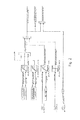
- the FIG. 1 shows a portion of an internal combustion engine A in an embodiment shown here as gasoline engine.
- the pressure wave supercharger B has four channels (1, 2, 3, 4) connected to these. These are the channel 1 (1) in the area of the intake fresh air, the channel 2 (2) in the region of the compressed fresh air for feeding to a charge air cooler J and an adjoining throttle valve K after which the compressed fresh air is supplied to the combustion chamber 10. Further, a passage 3 (3), which is disposed after the exhaust valve 6 and a catalyst in front of the pressure wave supercharger B, for introducing the exhaust gas into the supercharger B. Also arranged in the channel 3 (3) is a gas pocket valve with a gas pocket valve actuator F. In the region of the exhaust line S, the pressure wave supercharger B, the channel 4 (4) for discharging the exhaust gas after the compression process in the pressure wave supercharger B. The channel 4 (4) also has an oxidation catalyst M.
- a sectional view through the cylinder wherein an inlet valve 5, an outlet valve 6, a piston 7, a spark plug 8, a Injector 9 and a combustion chamber 10 is shown.
- a pressure wave supercharger B is connected to the internal combustion engine A.
- the pressure wave supercharger B furthermore has a cold gas housing side 11 and a hot gas housing side 12.
- an actuating element D is arranged in the cold gas housing half 11.
- the actuator D is controlled by a Steuerusionnstellmotor.
- the arranged in the pressure wave supercharger B rotor C is driven by an electric rotor motor E.
- the fresh air sucked in follows a path through the channel 1 (1) into the rotor cell 13 adjacent to the channel 1 (1) and is compressed in the pressure wave supercharger B.
- the compressed air is then supplied to the inlet valve 5 via the channel 2 (2) in the outlet region of the channel 2 (2).
- a recirculation valve with associated servomotor H in channel 2 (2) is interposed still arranged to bypass the intercooler and the combustion chamber 10 through a bypass line.
- the charge air cooler J the compressed and heated air is cooled so that its volume decreases, which leads to a higher degree of cylinder filling in the combustion chamber 10.
- the exhaust stroke the exhaust gas formed in the combustion chamber 10 through the channel 3 (3) the pressure wave supercharger B is fed back to the hot gas side.
- a catalyst L is interposed, which carries out a first exhaust aftertreatment.
- the gas pocket valve F driven via a gas pocket valve motor F increased entry of residual gas into the rotor cells 13 via the inlet opening of the channel 3 '(3') allows and / or exhaust past the rotor leads directly in channel 4 (4).
- the pressure wave compresses the fresh air drawn in through the channel 1 and ensures that the compressed fresh air flows into the channel 2 (2) and is subsequently transferred into the exhaust gas line through the outlet opening of the rotor cells at the channel 4 (4).
- the exhaust gas then flows through optionally further exhaust aftertreatment components, for example in the form of an oxidation catalyst M.
- Position 1 shows a tap of measurement data in the intake area of the fresh air.
- Pos. 2 US shows a tap of measures in the compressed fresh air before the intercooler J.
- Pos. 2 DS shows a tap after the throttle K just before the inlet valve 5 of the internal combustion engine A.
- Pos. 3 US shows a possible tap point in the anal. 3 (3).
- Pos. 3 DS shows a measuring point in channel 3 (3) before entering the pressure wave charger B.
- Pos. 3 US and 3 DS are each selected so that they measure the total flow after or in front of the recirculation valve H or gas pocket valve F. to provide readings for a recirculation valve position or gas pocket valve position.
- Pos. 4 shows a possible measurement point in the exhaust line S after the pressure wave loader B.
- the measuring positions shown here have proven to be advantageous in the invention, but can be supplemented or reduced depending on the application to other measurement positions and also set freely selectable in their local position become.
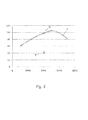
- FIG. 3 shows in a schematic embodiment, a characteristic diagram of an internal combustion engine in which once again is shown schematically how the relative engine power results.
- the engine power in kW is shown in the characteristic diagram on the Y axis and the engine speed in rpm on the X axis.
- a desired engine power is requested by the accelerator pedal position at an operating point which is at 4,000 rpm, then a desired operating point results, which in FIG. 3 represented by the dot.
- the maximum achievable engine power at 4,000 revolutions is limited on the preload line V and marked with the point Me.
Landscapes
- Engineering & Computer Science (AREA)
- Mechanical Engineering (AREA)
- General Engineering & Computer Science (AREA)
- Chemical & Material Sciences (AREA)
- Combustion & Propulsion (AREA)
- Supercharger (AREA)
Applications Claiming Priority (1)
| Application Number | Priority Date | Filing Date | Title |
|---|---|---|---|
| DE201110051559 DE102011051559B3 (de) | 2011-07-05 | 2011-07-05 | Verfahren zur Einstellung eines Ladedrucks einer Verbrennungskraftmaschine |
Publications (3)
| Publication Number | Publication Date |
|---|---|
| EP2543843A2 true EP2543843A2 (fr) | 2013-01-09 |
| EP2543843A3 EP2543843A3 (fr) | 2014-04-16 |
| EP2543843B1 EP2543843B1 (fr) | 2014-10-22 |
Family
ID=46177234
Family Applications (1)
| Application Number | Title | Priority Date | Filing Date |
|---|---|---|---|
| EP20120166761 Not-in-force EP2543843B1 (fr) | 2011-07-05 | 2012-05-04 | Procédé de réglage d'une pression d'admission d'un moteur à combustion interne |
Country Status (3)
| Country | Link |
|---|---|
| EP (1) | EP2543843B1 (fr) |
| JP (1) | JP2013015136A (fr) |
| DE (1) | DE102011051559B3 (fr) |
Citations (3)
| Publication number | Priority date | Publication date | Assignee | Title |
|---|---|---|---|---|
| DE4034341A1 (de) | 1989-11-16 | 1991-05-23 | Comprex Ag Baden | Verfahren und einrichtung zum betreiben einer gasdynamischen druckwellenmaschine |
| DE69823039T2 (de) | 1997-08-29 | 2004-11-25 | Swissauto Engineering S.A. | Gasdynamische druckwellenmaschine |
| DE102006020522A1 (de) | 2006-05-03 | 2007-11-08 | Robert Bosch Gmbh | Verfahren zum Betreiben einer Brennkraftmaschine |
Family Cites Families (4)
| Publication number | Priority date | Publication date | Assignee | Title |
|---|---|---|---|---|
| CH666521A5 (de) * | 1985-04-30 | 1988-07-29 | Bbc Brown Boveri & Cie | Druckwellenlader fuer einen verbrennungsmotor mit einer einrichtung zur steuerung des hochdruckabgasstromes. |
| US5724949A (en) * | 1996-11-06 | 1998-03-10 | Caterpillar Inc. | Hydraulic drive for a pressure wave supercharger utilized with an internal combustion engine |
| DE59711033D1 (de) * | 1997-08-29 | 2003-12-24 | Swissauto Eng Sa | Gasdynamische Druckwellenmaschine |
| CN102713194A (zh) * | 2009-10-30 | 2012-10-03 | 丰田自动车株式会社 | 内燃机的增压系统 |
-
2011
- 2011-07-05 DE DE201110051559 patent/DE102011051559B3/de not_active Expired - Fee Related
-
2012
- 2012-05-04 EP EP20120166761 patent/EP2543843B1/fr not_active Not-in-force
- 2012-06-26 JP JP2012142850A patent/JP2013015136A/ja active Pending
Patent Citations (3)
| Publication number | Priority date | Publication date | Assignee | Title |
|---|---|---|---|---|
| DE4034341A1 (de) | 1989-11-16 | 1991-05-23 | Comprex Ag Baden | Verfahren und einrichtung zum betreiben einer gasdynamischen druckwellenmaschine |
| DE69823039T2 (de) | 1997-08-29 | 2004-11-25 | Swissauto Engineering S.A. | Gasdynamische druckwellenmaschine |
| DE102006020522A1 (de) | 2006-05-03 | 2007-11-08 | Robert Bosch Gmbh | Verfahren zum Betreiben einer Brennkraftmaschine |
Also Published As
| Publication number | Publication date |
|---|---|
| EP2543843A3 (fr) | 2014-04-16 |
| EP2543843B1 (fr) | 2014-10-22 |
| DE102011051559B3 (de) | 2012-08-16 |
| JP2013015136A (ja) | 2013-01-24 |
Similar Documents
| Publication | Publication Date | Title |
|---|---|---|
| DE102012223772B4 (de) | Steuervorrichtung für Verbrennungskraftmaschine und Verfahren zum Steuern einer Verbrennungskraftmaschine | |
| DE102010048967B4 (de) | Turboladersteuerungssysteme für ein verbessertes Übergangsverhalten | |
| DE60114987T2 (de) | Regelung eines abgasturboladers mit variabler turbinengeometrie durch messung des abgasdrucks | |
| DE102017217796B4 (de) | Steuereinrichtung und Steuerverfahren für einen Auflader-ausgestatteten Verbrennungsmotor | |
| EP3034843B1 (fr) | Procédé de commande d'un dispositif de frein moteur et dispositif de frein moteur | |
| DE102015201061B4 (de) | Pumpverlustberechnungsvorrichtung für Verbrennungsmotor | |
| AT515499B1 (de) | Verfahren zum Betreiben einer Brennkraftmaschine | |
| DE102019209028A1 (de) | Steuervorrichtung für Verbrennungsmotor | |
| DE3032218A1 (de) | Kolbenbrennkraftmaschine mit einem abgasturbolader | |
| DE102018110949A1 (de) | Steuerungsvorrichtung für einen Verbrennungsmotor mit einem Turbolader | |
| DE102010043897B4 (de) | Verfahren und Vorrichtung zum Betreiben eines Verbrennungsmotors | |
| DE102006042872B4 (de) | Verfahren zur Bestimmung des Abgasgegendrucks stromaufwärts einer Turbine eines Abgasturboladers | |
| EP1623103A1 (fr) | Procede pour controler le regime d'un bi-turbocompresseur | |
| DE102017120838A1 (de) | Automatisches kalibrierungssystem und verfahren für einen dualkraftstoff-verbrennungsmotor | |
| DE102011079726A1 (de) | Verfahren und System zur Steuerung eines Motors | |
| EP2923073A1 (fr) | Procédé pour faire fonctionner un moteur à combustion interne à allumage extérieur comprenant un turbocompresseur à gaz d'échappement | |
| DE102009010633A1 (de) | Verfahren und System zur Verringerung des spezifischen Kraftstoffverbrauchs eines Motors bei instationären Betriebsbedingungen | |
| EP1788220B1 (fr) | Procédé de commande pour commander un turbocompresseur avec commande de la pression de suralimentation dans le côté de la turbine et une vanne de dérivation | |
| EP2562381A1 (fr) | Procédé de régulation de la pression de suralimentation dans un moteur à combustion interne équipé d'un compresseur à ondes de pression | |
| DE102004003607B4 (de) | Verfahren und Vorrichtung zur Steuerung eines elektrisch angetriebenen Verdichters einer Verbrennungskraftmaschine | |
| EP2543843B1 (fr) | Procédé de réglage d'une pression d'admission d'un moteur à combustion interne | |
| DE102007000324B4 (de) | Steuersystem für eine Brennkraftmaschine mit einem Aufladegerät | |
| DE102011081949A1 (de) | Verfahren und Vorrichtung zur Durchführung einer Regelung, insbesondere zum Einsatz in einem Kraftfahrzeug | |
| DE102011052749B4 (de) | Differenzdruckmessung an einem Druckwellenlader | |
| DE102018218483A1 (de) | Verfahren und Vorrichtung zum Betreiben eines aufgeladenen Verbrennungsmotors |
Legal Events
| Date | Code | Title | Description |
|---|---|---|---|
| PUAI | Public reference made under article 153(3) epc to a published international application that has entered the european phase |
Free format text: ORIGINAL CODE: 0009012 |
|
| AK | Designated contracting states |
Kind code of ref document: A2 Designated state(s): AL AT BE BG CH CY CZ DE DK EE ES FI FR GB GR HR HU IE IS IT LI LT LU LV MC MK MT NL NO PL PT RO RS SE SI SK SM TR |
|
| AX | Request for extension of the european patent |
Extension state: BA ME |
|
| PUAL | Search report despatched |
Free format text: ORIGINAL CODE: 0009013 |
|
| AK | Designated contracting states |
Kind code of ref document: A3 Designated state(s): AL AT BE BG CH CY CZ DE DK EE ES FI FR GB GR HR HU IE IS IT LI LT LU LV MC MK MT NL NO PL PT RO RS SE SI SK SM TR |
|
| AX | Request for extension of the european patent |
Extension state: BA ME |
|
| RIC1 | Information provided on ipc code assigned before grant |
Ipc: F04F 13/00 20090101ALN20140310BHEP Ipc: F02B 33/42 20060101AFI20140310BHEP |
|
| 17P | Request for examination filed |
Effective date: 20140423 |
|
| GRAP | Despatch of communication of intention to grant a patent |
Free format text: ORIGINAL CODE: EPIDOSNIGR1 |
|
| RIC1 | Information provided on ipc code assigned before grant |
Ipc: F02B 33/42 20060101AFI20140715BHEP Ipc: F04F 13/00 20090101ALN20140715BHEP |
|
| INTG | Intention to grant announced |
Effective date: 20140812 |
|
| GRAS | Grant fee paid |
Free format text: ORIGINAL CODE: EPIDOSNIGR3 |
|
| GRAA | (expected) grant |
Free format text: ORIGINAL CODE: 0009210 |
|
| AK | Designated contracting states |
Kind code of ref document: B1 Designated state(s): AL AT BE BG CH CY CZ DE DK EE ES FI FR GB GR HR HU IE IS IT LI LT LU LV MC MK MT NL NO PL PT RO RS SE SI SK SM TR |
|
| RAP1 | Party data changed (applicant data changed or rights of an application transferred) |
Owner name: BENTELER AUTOMOBILTECHNIK GMBH |
|
| REG | Reference to a national code |
Ref country code: GB Ref legal event code: FG4D Free format text: NOT ENGLISH |
|
| REG | Reference to a national code |
Ref country code: CH Ref legal event code: EP |
|
| REG | Reference to a national code |
Ref country code: AT Ref legal event code: REF Ref document number: 692778 Country of ref document: AT Kind code of ref document: T Effective date: 20141115 |
|
| REG | Reference to a national code |
Ref country code: IE Ref legal event code: FG4D Free format text: LANGUAGE OF EP DOCUMENT: GERMAN |
|
| REG | Reference to a national code |
Ref country code: DE Ref legal event code: R096 Ref document number: 502012001464 Country of ref document: DE Effective date: 20141204 |
|
| REG | Reference to a national code |
Ref country code: NL Ref legal event code: VDEP Effective date: 20141022 |
|
| REG | Reference to a national code |
Ref country code: LT Ref legal event code: MG4D |
|
| PG25 | Lapsed in a contracting state [announced via postgrant information from national office to epo] |
Ref country code: ES Free format text: LAPSE BECAUSE OF FAILURE TO SUBMIT A TRANSLATION OF THE DESCRIPTION OR TO PAY THE FEE WITHIN THE PRESCRIBED TIME-LIMIT Effective date: 20141022 Ref country code: NO Free format text: LAPSE BECAUSE OF FAILURE TO SUBMIT A TRANSLATION OF THE DESCRIPTION OR TO PAY THE FEE WITHIN THE PRESCRIBED TIME-LIMIT Effective date: 20150122 Ref country code: IS Free format text: LAPSE BECAUSE OF FAILURE TO SUBMIT A TRANSLATION OF THE DESCRIPTION OR TO PAY THE FEE WITHIN THE PRESCRIBED TIME-LIMIT Effective date: 20150222 Ref country code: PT Free format text: LAPSE BECAUSE OF FAILURE TO SUBMIT A TRANSLATION OF THE DESCRIPTION OR TO PAY THE FEE WITHIN THE PRESCRIBED TIME-LIMIT Effective date: 20150223 Ref country code: LT Free format text: LAPSE BECAUSE OF FAILURE TO SUBMIT A TRANSLATION OF THE DESCRIPTION OR TO PAY THE FEE WITHIN THE PRESCRIBED TIME-LIMIT Effective date: 20141022 Ref country code: NL Free format text: LAPSE BECAUSE OF FAILURE TO SUBMIT A TRANSLATION OF THE DESCRIPTION OR TO PAY THE FEE WITHIN THE PRESCRIBED TIME-LIMIT Effective date: 20141022 Ref country code: FI Free format text: LAPSE BECAUSE OF FAILURE TO SUBMIT A TRANSLATION OF THE DESCRIPTION OR TO PAY THE FEE WITHIN THE PRESCRIBED TIME-LIMIT Effective date: 20141022 |
|
| PG25 | Lapsed in a contracting state [announced via postgrant information from national office to epo] |
Ref country code: CY Free format text: LAPSE BECAUSE OF FAILURE TO SUBMIT A TRANSLATION OF THE DESCRIPTION OR TO PAY THE FEE WITHIN THE PRESCRIBED TIME-LIMIT Effective date: 20141022 Ref country code: RS Free format text: LAPSE BECAUSE OF FAILURE TO SUBMIT A TRANSLATION OF THE DESCRIPTION OR TO PAY THE FEE WITHIN THE PRESCRIBED TIME-LIMIT Effective date: 20141022 Ref country code: GR Free format text: LAPSE BECAUSE OF FAILURE TO SUBMIT A TRANSLATION OF THE DESCRIPTION OR TO PAY THE FEE WITHIN THE PRESCRIBED TIME-LIMIT Effective date: 20150123 Ref country code: LV Free format text: LAPSE BECAUSE OF FAILURE TO SUBMIT A TRANSLATION OF THE DESCRIPTION OR TO PAY THE FEE WITHIN THE PRESCRIBED TIME-LIMIT Effective date: 20141022 Ref country code: PL Free format text: LAPSE BECAUSE OF FAILURE TO SUBMIT A TRANSLATION OF THE DESCRIPTION OR TO PAY THE FEE WITHIN THE PRESCRIBED TIME-LIMIT Effective date: 20141022 Ref country code: SE Free format text: LAPSE BECAUSE OF FAILURE TO SUBMIT A TRANSLATION OF THE DESCRIPTION OR TO PAY THE FEE WITHIN THE PRESCRIBED TIME-LIMIT Effective date: 20141022 Ref country code: HR Free format text: LAPSE BECAUSE OF FAILURE TO SUBMIT A TRANSLATION OF THE DESCRIPTION OR TO PAY THE FEE WITHIN THE PRESCRIBED TIME-LIMIT Effective date: 20141022 |
|
| REG | Reference to a national code |
Ref country code: DE Ref legal event code: R097 Ref document number: 502012001464 Country of ref document: DE |
|
| PG25 | Lapsed in a contracting state [announced via postgrant information from national office to epo] |
Ref country code: EE Free format text: LAPSE BECAUSE OF FAILURE TO SUBMIT A TRANSLATION OF THE DESCRIPTION OR TO PAY THE FEE WITHIN THE PRESCRIBED TIME-LIMIT Effective date: 20141022 Ref country code: DK Free format text: LAPSE BECAUSE OF FAILURE TO SUBMIT A TRANSLATION OF THE DESCRIPTION OR TO PAY THE FEE WITHIN THE PRESCRIBED TIME-LIMIT Effective date: 20141022 Ref country code: CZ Free format text: LAPSE BECAUSE OF FAILURE TO SUBMIT A TRANSLATION OF THE DESCRIPTION OR TO PAY THE FEE WITHIN THE PRESCRIBED TIME-LIMIT Effective date: 20141022 Ref country code: SK Free format text: LAPSE BECAUSE OF FAILURE TO SUBMIT A TRANSLATION OF THE DESCRIPTION OR TO PAY THE FEE WITHIN THE PRESCRIBED TIME-LIMIT Effective date: 20141022 Ref country code: RO Free format text: LAPSE BECAUSE OF FAILURE TO SUBMIT A TRANSLATION OF THE DESCRIPTION OR TO PAY THE FEE WITHIN THE PRESCRIBED TIME-LIMIT Effective date: 20141022 |
|
| PLBE | No opposition filed within time limit |
Free format text: ORIGINAL CODE: 0009261 |
|
| STAA | Information on the status of an ep patent application or granted ep patent |
Free format text: STATUS: NO OPPOSITION FILED WITHIN TIME LIMIT |
|
| PG25 | Lapsed in a contracting state [announced via postgrant information from national office to epo] |
Ref country code: IT Free format text: LAPSE BECAUSE OF FAILURE TO SUBMIT A TRANSLATION OF THE DESCRIPTION OR TO PAY THE FEE WITHIN THE PRESCRIBED TIME-LIMIT Effective date: 20141022 |
|
| 26N | No opposition filed |
Effective date: 20150723 |
|
| REG | Reference to a national code |
Ref country code: CH Ref legal event code: PL |
|
| PG25 | Lapsed in a contracting state [announced via postgrant information from national office to epo] |
Ref country code: MC Free format text: LAPSE BECAUSE OF FAILURE TO SUBMIT A TRANSLATION OF THE DESCRIPTION OR TO PAY THE FEE WITHIN THE PRESCRIBED TIME-LIMIT Effective date: 20141022 Ref country code: CH Free format text: LAPSE BECAUSE OF NON-PAYMENT OF DUE FEES Effective date: 20150531 Ref country code: LU Free format text: LAPSE BECAUSE OF FAILURE TO SUBMIT A TRANSLATION OF THE DESCRIPTION OR TO PAY THE FEE WITHIN THE PRESCRIBED TIME-LIMIT Effective date: 20150504 Ref country code: LI Free format text: LAPSE BECAUSE OF NON-PAYMENT OF DUE FEES Effective date: 20150531 |
|
| REG | Reference to a national code |
Ref country code: IE Ref legal event code: MM4A |
|
| PG25 | Lapsed in a contracting state [announced via postgrant information from national office to epo] |
Ref country code: SI Free format text: LAPSE BECAUSE OF FAILURE TO SUBMIT A TRANSLATION OF THE DESCRIPTION OR TO PAY THE FEE WITHIN THE PRESCRIBED TIME-LIMIT Effective date: 20141022 |
|
| PG25 | Lapsed in a contracting state [announced via postgrant information from national office to epo] |
Ref country code: IE Free format text: LAPSE BECAUSE OF NON-PAYMENT OF DUE FEES Effective date: 20150504 |
|
| REG | Reference to a national code |
Ref country code: FR Ref legal event code: PLFP Year of fee payment: 5 |
|
| PGFP | Annual fee paid to national office [announced via postgrant information from national office to epo] |
Ref country code: GB Payment date: 20160520 Year of fee payment: 5 Ref country code: DE Payment date: 20160519 Year of fee payment: 5 |
|
| PGFP | Annual fee paid to national office [announced via postgrant information from national office to epo] |
Ref country code: FR Payment date: 20160520 Year of fee payment: 5 |
|
| PG25 | Lapsed in a contracting state [announced via postgrant information from national office to epo] |
Ref country code: MT Free format text: LAPSE BECAUSE OF FAILURE TO SUBMIT A TRANSLATION OF THE DESCRIPTION OR TO PAY THE FEE WITHIN THE PRESCRIBED TIME-LIMIT Effective date: 20141022 |
|
| PG25 | Lapsed in a contracting state [announced via postgrant information from national office to epo] |
Ref country code: SM Free format text: LAPSE BECAUSE OF FAILURE TO SUBMIT A TRANSLATION OF THE DESCRIPTION OR TO PAY THE FEE WITHIN THE PRESCRIBED TIME-LIMIT Effective date: 20141022 Ref country code: BG Free format text: LAPSE BECAUSE OF FAILURE TO SUBMIT A TRANSLATION OF THE DESCRIPTION OR TO PAY THE FEE WITHIN THE PRESCRIBED TIME-LIMIT Effective date: 20141022 Ref country code: HU Free format text: LAPSE BECAUSE OF FAILURE TO SUBMIT A TRANSLATION OF THE DESCRIPTION OR TO PAY THE FEE WITHIN THE PRESCRIBED TIME-LIMIT; INVALID AB INITIO Effective date: 20120504 |
|
| PG25 | Lapsed in a contracting state [announced via postgrant information from national office to epo] |
Ref country code: BE Free format text: LAPSE BECAUSE OF NON-PAYMENT OF DUE FEES Effective date: 20150531 |
|
| PG25 | Lapsed in a contracting state [announced via postgrant information from national office to epo] |
Ref country code: TR Free format text: LAPSE BECAUSE OF FAILURE TO SUBMIT A TRANSLATION OF THE DESCRIPTION OR TO PAY THE FEE WITHIN THE PRESCRIBED TIME-LIMIT Effective date: 20141022 |
|
| REG | Reference to a national code |
Ref country code: DE Ref legal event code: R119 Ref document number: 502012001464 Country of ref document: DE |
|
| GBPC | Gb: european patent ceased through non-payment of renewal fee |
Effective date: 20170504 |
|
| REG | Reference to a national code |
Ref country code: FR Ref legal event code: ST Effective date: 20180131 |
|
| PG25 | Lapsed in a contracting state [announced via postgrant information from national office to epo] |
Ref country code: DE Free format text: LAPSE BECAUSE OF NON-PAYMENT OF DUE FEES Effective date: 20171201 Ref country code: GB Free format text: LAPSE BECAUSE OF NON-PAYMENT OF DUE FEES Effective date: 20170504 |
|
| PG25 | Lapsed in a contracting state [announced via postgrant information from national office to epo] |
Ref country code: FR Free format text: LAPSE BECAUSE OF NON-PAYMENT OF DUE FEES Effective date: 20170531 |
|
| PG25 | Lapsed in a contracting state [announced via postgrant information from national office to epo] |
Ref country code: MK Free format text: LAPSE BECAUSE OF FAILURE TO SUBMIT A TRANSLATION OF THE DESCRIPTION OR TO PAY THE FEE WITHIN THE PRESCRIBED TIME-LIMIT Effective date: 20141022 |
|
| REG | Reference to a national code |
Ref country code: AT Ref legal event code: MM01 Ref document number: 692778 Country of ref document: AT Kind code of ref document: T Effective date: 20170504 |
|
| PG25 | Lapsed in a contracting state [announced via postgrant information from national office to epo] |
Ref country code: AT Free format text: LAPSE BECAUSE OF NON-PAYMENT OF DUE FEES Effective date: 20170504 |
|
| PG25 | Lapsed in a contracting state [announced via postgrant information from national office to epo] |
Ref country code: AL Free format text: LAPSE BECAUSE OF FAILURE TO SUBMIT A TRANSLATION OF THE DESCRIPTION OR TO PAY THE FEE WITHIN THE PRESCRIBED TIME-LIMIT Effective date: 20141022 |