EP2543868A2 - Fantriebwerk - Google Patents
Fantriebwerk Download PDFInfo
- Publication number
- EP2543868A2 EP2543868A2 EP12174829A EP12174829A EP2543868A2 EP 2543868 A2 EP2543868 A2 EP 2543868A2 EP 12174829 A EP12174829 A EP 12174829A EP 12174829 A EP12174829 A EP 12174829A EP 2543868 A2 EP2543868 A2 EP 2543868A2
- Authority
- EP
- European Patent Office
- Prior art keywords
- spool
- compressor
- support
- gas turbine
- lift
- Prior art date
- Legal status (The legal status is an assumption and is not a legal conclusion. Google has not performed a legal analysis and makes no representation as to the accuracy of the status listed.)
- Granted
Links
Images


Classifications
-
- F—MECHANICAL ENGINEERING; LIGHTING; HEATING; WEAPONS; BLASTING
- F02—COMBUSTION ENGINES; HOT-GAS OR COMBUSTION-PRODUCT ENGINE PLANTS
- F02C—GAS-TURBINE PLANTS; AIR INTAKES FOR JET-PROPULSION PLANTS; CONTROLLING FUEL SUPPLY IN AIR-BREATHING JET-PROPULSION PLANTS
- F02C7/00—Features, components parts, details or accessories, not provided for in, or of interest apart form groups F02C1/00 - F02C6/00; Air intakes for jet-propulsion plants
- F02C7/36—Power transmission arrangements between the different shafts of the gas turbine plant, or between the gas-turbine plant and the power user
-
- F—MECHANICAL ENGINEERING; LIGHTING; HEATING; WEAPONS; BLASTING
- F01—MACHINES OR ENGINES IN GENERAL; ENGINE PLANTS IN GENERAL; STEAM ENGINES
- F01D—NON-POSITIVE DISPLACEMENT MACHINES OR ENGINES, e.g. STEAM TURBINES
- F01D25/00—Component parts, details, or accessories, not provided for in, or of interest apart from, other groups
- F01D25/28—Supporting or mounting arrangements, e.g. for turbine casing
- F01D25/285—Temporary support structures, e.g. for testing, assembling, installing, repairing; Assembly methods using such structures
-
- F—MECHANICAL ENGINEERING; LIGHTING; HEATING; WEAPONS; BLASTING
- F02—COMBUSTION ENGINES; HOT-GAS OR COMBUSTION-PRODUCT ENGINE PLANTS
- F02K—JET-PROPULSION PLANTS
- F02K3/00—Plants including a gas turbine driving a compressor or a ducted fan
- F02K3/02—Plants including a gas turbine driving a compressor or a ducted fan in which part of the working fluid by-passes the turbine and combustion chamber
- F02K3/04—Plants including a gas turbine driving a compressor or a ducted fan in which part of the working fluid by-passes the turbine and combustion chamber the plant including ducted fans, i.e. fans with high volume, low pressure outputs, for augmenting the jet thrust, e.g. of double-flow type
- F02K3/06—Plants including a gas turbine driving a compressor or a ducted fan in which part of the working fluid by-passes the turbine and combustion chamber the plant including ducted fans, i.e. fans with high volume, low pressure outputs, for augmenting the jet thrust, e.g. of double-flow type with front fan
-
- F—MECHANICAL ENGINEERING; LIGHTING; HEATING; WEAPONS; BLASTING
- F05—INDEXING SCHEMES RELATING TO ENGINES OR PUMPS IN VARIOUS SUBCLASSES OF CLASSES F01-F04
- F05D—INDEXING SCHEME FOR ASPECTS RELATING TO NON-POSITIVE-DISPLACEMENT MACHINES OR ENGINES, GAS-TURBINES OR JET-PROPULSION PLANTS
- F05D2230/00—Manufacture
- F05D2230/60—Assembly methods
- F05D2230/68—Assembly methods using auxiliary equipment for lifting or holding
-
- F—MECHANICAL ENGINEERING; LIGHTING; HEATING; WEAPONS; BLASTING
- F05—INDEXING SCHEMES RELATING TO ENGINES OR PUMPS IN VARIOUS SUBCLASSES OF CLASSES F01-F04
- F05D—INDEXING SCHEME FOR ASPECTS RELATING TO NON-POSITIVE-DISPLACEMENT MACHINES OR ENGINES, GAS-TURBINES OR JET-PROPULSION PLANTS
- F05D2260/00—Function
- F05D2260/02—Transport and handling during maintenance and repair
-
- Y—GENERAL TAGGING OF NEW TECHNOLOGICAL DEVELOPMENTS; GENERAL TAGGING OF CROSS-SECTIONAL TECHNOLOGIES SPANNING OVER SEVERAL SECTIONS OF THE IPC; TECHNICAL SUBJECTS COVERED BY FORMER USPC CROSS-REFERENCE ART COLLECTIONS [XRACs] AND DIGESTS
- Y02—TECHNOLOGIES OR APPLICATIONS FOR MITIGATION OR ADAPTATION AGAINST CLIMATE CHANGE
- Y02T—CLIMATE CHANGE MITIGATION TECHNOLOGIES RELATED TO TRANSPORTATION
- Y02T50/00—Aeronautics or air transport
- Y02T50/60—Efficient propulsion technologies, e.g. for aircraft
-
- Y—GENERAL TAGGING OF NEW TECHNOLOGICAL DEVELOPMENTS; GENERAL TAGGING OF CROSS-SECTIONAL TECHNOLOGIES SPANNING OVER SEVERAL SECTIONS OF THE IPC; TECHNICAL SUBJECTS COVERED BY FORMER USPC CROSS-REFERENCE ART COLLECTIONS [XRACs] AND DIGESTS
- Y10—TECHNICAL SUBJECTS COVERED BY FORMER USPC
- Y10T—TECHNICAL SUBJECTS COVERED BY FORMER US CLASSIFICATION
- Y10T29/00—Metal working
- Y10T29/49—Method of mechanical manufacture
- Y10T29/49316—Impeller making
- Y10T29/49318—Repairing or disassembling
-
- Y—GENERAL TAGGING OF NEW TECHNOLOGICAL DEVELOPMENTS; GENERAL TAGGING OF CROSS-SECTIONAL TECHNOLOGIES SPANNING OVER SEVERAL SECTIONS OF THE IPC; TECHNICAL SUBJECTS COVERED BY FORMER USPC CROSS-REFERENCE ART COLLECTIONS [XRACs] AND DIGESTS
- Y10—TECHNICAL SUBJECTS COVERED BY FORMER USPC
- Y10T—TECHNICAL SUBJECTS COVERED BY FORMER US CLASSIFICATION
- Y10T29/00—Metal working
- Y10T29/49—Method of mechanical manufacture
- Y10T29/49316—Impeller making
- Y10T29/4932—Turbomachine making
-
- Y—GENERAL TAGGING OF NEW TECHNOLOGICAL DEVELOPMENTS; GENERAL TAGGING OF CROSS-SECTIONAL TECHNOLOGIES SPANNING OVER SEVERAL SECTIONS OF THE IPC; TECHNICAL SUBJECTS COVERED BY FORMER USPC CROSS-REFERENCE ART COLLECTIONS [XRACs] AND DIGESTS
- Y10—TECHNICAL SUBJECTS COVERED BY FORMER USPC
- Y10T—TECHNICAL SUBJECTS COVERED BY FORMER US CLASSIFICATION
- Y10T29/00—Metal working
- Y10T29/49—Method of mechanical manufacture
- Y10T29/49718—Repairing
-
- Y—GENERAL TAGGING OF NEW TECHNOLOGICAL DEVELOPMENTS; GENERAL TAGGING OF CROSS-SECTIONAL TECHNOLOGIES SPANNING OVER SEVERAL SECTIONS OF THE IPC; TECHNICAL SUBJECTS COVERED BY FORMER USPC CROSS-REFERENCE ART COLLECTIONS [XRACs] AND DIGESTS
- Y10—TECHNICAL SUBJECTS COVERED BY FORMER USPC
- Y10T—TECHNICAL SUBJECTS COVERED BY FORMER US CLASSIFICATION
- Y10T29/00—Metal working
- Y10T29/49—Method of mechanical manufacture
- Y10T29/49815—Disassembling
Definitions
- This invention relates generally to gas turbine engines, and specifically to turbofan engines for aircraft.
- the invention concerns a repair or maintenance apparatus for the fan disk and rotor assembly of a turbofan engine.
- Gas turbine engines are built around a power core made up of a compressor, combustor and turbine, arranged in flow series with an upstream inlet and downstream exhaust.
- the compressor compresses air from the inlet, which is mixed which fuel in the combustor and ignited to generate hot combustion gas.
- the turbine extracts energy from the expanding combustion gas, and drives the compressor via a common shaft. Energy is delivered in the form of rotational energy in the shaft or reactive thrust from the exhaust, or both.
- Gas turbine engines provide reliable, efficient sources of energy for a wide range of applications, including industrial power generation, aviation and commercial heating and cooling.
- Larger-scale gas turbine engines include a number of different compressor and turbine sections, which are arranged into coaxially nested spools. The spools operate at different pressures and temperatures, and rotate at different speeds.
- Individual compressor and turbine sections are subdivided into a number of stages, which are formed of alternating rows of rotor blade and stator vane airfoils. The airfoils are shaped to turn, accelerate and compress the gas flow, and to generate lift for conversion to rotational energy in the turbine.
- Turbojets are an older configuration, in which thrust is generated primarily from the exhaust.
- Modem turbofan and turboprop engines typically utilize a two-or three-spool arrangements, in which the low-pressure spool is coupled to a propulsion fan or propeller.
- Turboshaft engines are used on rotary-wing aircraft, including helicopters.
- Turbofans are commonly divided into high and low bypass engines.
- High-bypass turbofans generate most of their thrust via the fan, which drives airflow through a bypass duct oriented around the engine core.
- Low-bypass turbofans generate more power from the exhaust flow, delivering greater specific thrust but at some cost in noise and fuel efficiency, and are used on supersonic fighters and other high-performance aircraft.
- This invention is directed to a maintenance apparatus for a gas turbine engine.
- the apparatus includes a spool lock configured to lock the compressor spool, and a lift configured to support a compressor or fan rotor during installation and removal.
- the spool lock includes an outer ring configured for attachment to the compressor case, an inner ring configured to support the compressor spool within the compressor case, and a web extending between the inner and outer rings.
- the lift includes a beam and a support strut configured for attachment to the flange of the gas turbine engine.
- the support strut may be pivotally attached to the beam, so that the beam can be oriented with respect to the rotational axis.
- the beam may include an axially translating hoist, which can be used to support the rotor during installation and removal from the compressor spool.
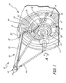
- FIG. 1 is a perspective view of fan disk maintenance apparatus 10 for gas turbine engine 12.
- Maintenance apparatus 10 includes spool lock 14 and lift 16 with hoist 18 for installation and removal of fan disk (or rotor) 20.
- FIG. 1 shows gas turbine (or turbofan) engine 12 with the nacelle removed, exposing annular front flange 22 on the front (axially forward) end of fan casing 24.
- Lift 16 attaches to flange 22, so that the weight of rotor 20 is supported from gas turbine engine 12 during installation and removal.
- Maintenance apparatus 10 provides for "on wing" maintenance operations on fan disks and other compressor, fan or turbine rotors 20, without removing gas turbine engine 12 from the aircraft, and without requiring a crane, external lift rig or other heavy equipment.
- Spool lock 14 is formed of strong, durable metal or metal alloy such as stainless steel or aluminum, and includes outer ring 26, inner ring 27 and web 28. Outer ring 26 is coupled to a stationary component of the compressor or fan casing, for example a booster flange, or an inner or outer diameter guide vane ring.
- Inner ring 27 of spool lock 14 locks compressor spool assembly 30 against rotation, and provides axial and radial support during installation and removal of rotor 20.
- Web 28 supports inner ring 27 from outer ring 26, with openings 31 to reduce weight and provide access to compressor blades 32, or other internal components of spool assembly 30.
- Lift 16 includes hoist beam 34 for supporting hoist 18, and adjustable struts 36 for supporting beam 34.
- First end 39 of beam 34 is attached to front flange 22 (or another flange structure) of gas turbine engine 12, using flush attachment member 40.
- Struts 36 are pivotally attached to second end 42 of beam 34, using hoist pivots 38.
- Struts 36 also attach to flange 22 of gas turbine engine 12, or another stationary component of fan casing 24, or another casing structure. Struts 36 have adjustable length, in order to position beam 34 in a level, horizontal orientation above spool assembly 30, and along rotational axis A of gas turbine engine 12. Beam 34 is positioned above and generally parallel to rotational axis A, as shown in FIG. 1 .
- gas turbine engine 12 includes a booster module (spool assembly 30) with a one-stage fan disk (or fan rotor) 20, and a low-pressure or "booster" compressor with one or more stages of compressor blades 32.
- Fan exit guide vanes (or other stators vanes) 44 are arranged downstream of rotor 20, extending radially from an inner diameter (ID) ring positioned about booster spool assembly 30, to an outer diameter (OD) ring at casing 24.
- spool assembly 30 includes a low-pressure, intermediate-pressure or high-pressure compressor spool, or a fan spool or a fan shaft assembly, with or without additional compressor stages.
- a geared drive mechanism is used to couple spool assembly 30 to rotor 20, providing independent fan speed control for reduced noise and increased efficiency.
- the number of fan stages also varies, with a corresponding number of axially spaced fan disks 20, in either co-rotating or counter-rotating configurations.
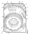
- FIG. 2 is a detail of spool lock 14 for maintenance apparatus 10 of FIG. 1 .
- Spool lock 14 includes outer ring 26, inner ring 27 and web 28 for supporting spool assembly 30 during installation and removal of rotor 20, as described above.
- Rotor 20 includes dovetail slots 50, which are used to attach radially-extending fan blades for rotation about fan or compressor shaft 45.
- Rotor 20 is removed from spool assembly 30 by releasing the mechanical attachments (e.g., bolts) connecting rotor 20 to shaft 45, and translating rotor 20 axially forward, away from rotor blades 32 and the other components of spool assembly 30.
- mechanical attachments e.g., bolts
- outer ring 26 of spool lock 14 is attached to a fixed component of compressor casing 48, for example using bolts 46 to attach outer ring 26 through the existing bolt holes in a booster flange.
- outer ring 26 of spool lock 14 is attached to a different (stationary) engine or compressor component, for example along the inner or outer diameter of vanes 44, or directly to casing 24.
- Inner ring 27 of spool lock 14 locks spool assembly 30 against rotation using additional bolts 46, which are spaced to use existing bolt holes in the spool shaft, or with other mechanical fasteners.
- Inner ring 27 also provides axial and radial support to the rotational components of spool assembly 30, so that rotor blades 32 and shaft 45 do not come loose or come into contact with the stationary structures of gas turbine engine 12.
- web 28 is formed as a number of tabbed features (e.g., six) arranged circumferentially about spool lock 14, extending between outer ring 26 and inner ring 27. Openings 31 are interspersed between the tab features, providing an open-web design to reduce weight and allow for easier handing and access. Alternatively, openings 31 are omitted, or made smaller, and web 28 provides a substantially continuous conical or frustoconical support structure between outer ring 26 and inner ring 27 of spool lock 14.
- FIG. 3 is a detail of lift 16 and beam 34 for fan disk maintenance apparatus 10 of FIG. 1 .
- Beam 34 supports hoist 18 with winch 52, slider 54 and chain 56. Slider 54 allows for axial translation of hoist 18 along beam 34.
- First end 39 of beam 34 is attached to flange 22 of casing 24 via hoist attachment (or coupler) 40, for example using bolts 46 to make a flush connection between attachment 40 and flange 22. Beam 34 is then suspended from attachment 40 via pin mechanism 57.
- casing 24 includes acoustic treatment 58.
- fan shaft lock 59 can be connected across flange 22 and coupled to the fan disk to lock the fan shaft against rotation during maintenance.
- FIG. 3 also shows spool assembly 30 with first-stage compressor vanes 60 still in place, before the installation of spool lock 14, as shown in FIG. 2 .
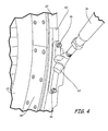
- FIG. 4 is a detail of support strut 36 for fan disk maintenance apparatus 10 of FIG. 1 .
- Support strut 36 is pivotally attached to casing 24 via strut coupler 62 and strut pivot 63.
- Strut coupler 62 is attached to casing 24, for example by flush mount attachment using bolts 46 through existing bolt holes in flange 22.
- Pivot 63 provides for angular motion between strut 36 and casing 24, in order to position strut coupler 62 flush onto flange 22. Pivot 63 also provides for angular motion between strut 36 and flange 22, in order to position the beam parallel to the engine axis, as described above.
- holes for bolts 46 in strut coupler 62 are spaced to accommodate existing bolt holes in flange 22 (similarly for attachment 40 of FIG. 3 ).
- the existing bolt holes are not necessarily provided for use during maintenance, but are typically configured to attach other engine components to fan case 24, for example a forward fan case or nacelle.
- screws, clamps or other mechanical fastening devices are used in place of one or more bolts 46.
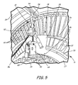
- FIG. 5 is a detail of hoist 18 for fan disk maintenance apparatus 10 of FIG. 1 .
- Hoist 18 includes winch 52, which is supported from beam 34 on slider 54.
- Chain 56 is connected to lift jig 64, which supports rotor 20.
- Winch 52 comprises a ratchet or other tensioning mechanism attached to chain 56, or to a cable or rope.
- Slider 54 includes a roller bearing or sliding mechanism, allowing hoist 18 and winch 52 to translate axially along beam 34.
- Chain 56 is attached to the rotor 20 using lift jig 64.
- Lift jig 64 includes dovetail member 65, which is shaped for insertion into one of slots 50 in rotor 20.
- Winch 52 is actuated to increase or decrease the tension in chain 56 and raise or lower rotor 20, and to support the weight of rotor 20 from beam 34 during installation and removal from spool assembly 30.
- FIG. 6 is a side view of fan rotor maintenance apparatus 10, with rotor 20 supported from beam 34.
- Rotor 20 is attached to hoist 18 via lift jig 64 and chain 56. As hoist 18 translates along beam 34, rotor 20 translates axially in and out of casing 24, for installation and removal from gas turbine engine 12.
- Rotor 20 is typically a lifetime limited part, which must be removed for maintenance or replacement after a finite number of engine hours, or a fixed number of takeoff and landing cycles.
- the entire booster (low pressure compressor) and fan assembly must often be removed in order to access rotor 20, requiring a large hangar with a crane and heavy tooling fixtures. Because not all regional facilities have this equipment, gas turbine engine 12 must be removed from the aircraft and shipped to a centralized overhaul center for maintenance, repair and replacement of rotor 20.
- fan disk maintenance apparatus 10 With fan disk maintenance apparatus 10, only rotor 20 is removed. Gas turbine engine 12 remains on the aircraft, with the rest of the low-pressure spool and booster assembly. This reduces the number of person-hours required to remove and replace rotor 20 by a factor of approximately two.
- maintenance apparatus 10 supports fan rotor 20 directly from flange 22 of gas turbine engine 12, so there is no need for an external crane or other heavy lifting equipment. This allows maintenance apparatus 10 to be used "on wing,” without removing gas turbine engine 12 from the aircraft, reducing downtime and increasing the utility and versatility of smaller-scale regional maintenance and repair facilities.
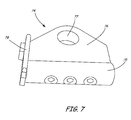
- FIG. 7 is a detail view of alternate lift jig 74 for fan disk maintenance apparatus 10 of FIG. 1 .
- lift jig 74 comprises dovetail member 75 attached to jig body 76 with jig attachment 77 and stop 78.
- Dovetail member 75 is shaped to fit into a fan blade retention slot on a fan disk, as described above. Depending on configuration, dovetail member 75 has an oblong or dovetail cross section, or a round, square, triangular or other geometry, depending on the shape of the fan disk and blade retention slots.
- Jig attachment 77 is formed as a hole or other structure in jig body 76 to attach a lift cable or chain, for example using a hook mechanism.
- Stop 78 is configured to limit axial movement of lift jig 74 when dovetail member 75 is positioned at a particular depth in the retention slot, so that the center of mass of the fan disk is approximately vertical with jig attachment 77, and the fan disk is vertically suspended from beam 34 during installation and removal.
Landscapes
- Engineering & Computer Science (AREA)
- Mechanical Engineering (AREA)
- General Engineering & Computer Science (AREA)
- Chemical & Material Sciences (AREA)
- Combustion & Propulsion (AREA)
- Structures Of Non-Positive Displacement Pumps (AREA)
Applications Claiming Priority (1)
| Application Number | Priority Date | Filing Date | Title |
|---|---|---|---|
| US13/176,521 US8814512B2 (en) | 2011-07-05 | 2011-07-05 | Fan disk apparatus and method |
Publications (3)
| Publication Number | Publication Date |
|---|---|
| EP2543868A2 true EP2543868A2 (de) | 2013-01-09 |
| EP2543868A3 EP2543868A3 (de) | 2016-09-14 |
| EP2543868B1 EP2543868B1 (de) | 2018-10-03 |
Family
ID=46456417
Family Applications (1)
| Application Number | Title | Priority Date | Filing Date |
|---|---|---|---|
| EP12174829.7A Active EP2543868B1 (de) | 2011-07-05 | 2012-07-03 | Fantriebwerk |
Country Status (2)
| Country | Link |
|---|---|
| US (1) | US8814512B2 (de) |
| EP (1) | EP2543868B1 (de) |
Cited By (5)
| Publication number | Priority date | Publication date | Assignee | Title |
|---|---|---|---|---|
| EP2949885A1 (de) * | 2014-05-26 | 2015-12-02 | Alstom Technology Ltd | Verfahren und vorrichtung zur montage und demontage einer turbinenkomponente |
| WO2015181017A3 (de) * | 2014-05-30 | 2016-02-25 | Lufthansa Technik Ag | Demontageverfahren für gasturbinen und kalibriervorrichtung |
| EP3023606A1 (de) * | 2014-11-18 | 2016-05-25 | Siemens Aktiengesellschaft | Gasturbine mit Hebevorrichtung |
| ITUB20152025A1 (it) * | 2015-07-09 | 2017-01-09 | Nuovo Pignone Tecnologie Srl | Apparato per la movimentazione di una parte di turbomacchina. |
| WO2018130479A1 (de) * | 2017-01-11 | 2018-07-19 | Siemens Aktiengesellschaft | Verfahren zur montage und/oder demontage von komponenten einer ein turbinengehäuse aufweisenden turbine, adapter und system zur verwendung in dem verfahren sowie verwendung eines adapters |
Families Citing this family (11)
| Publication number | Priority date | Publication date | Assignee | Title |
|---|---|---|---|---|
| US9976443B2 (en) | 2009-11-20 | 2018-05-22 | United Technologies Corporation | Turbofan engine assembly methods |
| EP3546726B1 (de) * | 2013-03-14 | 2021-12-15 | Raytheon Technologies Corporation | Turbofantriebwerkmontageverfahren |
| US9188007B2 (en) * | 2013-06-26 | 2015-11-17 | Siemens Energy, Inc. | Gas turbine shaft bearing system service tool and bearing system service method |
| EP3054107B1 (de) * | 2015-02-09 | 2017-12-06 | Rolls-Royce North American Technologies, Inc. | Turbinenanordnung mit einer sperreinrichtung des rotorsystems |
| US10132198B2 (en) * | 2016-01-06 | 2018-11-20 | Honda Motor Co., Ltd. | Support apparatus for disassembling and assembling gas turbine engine |
| US10704421B2 (en) | 2016-12-02 | 2020-07-07 | General Electric Company | Combustion liner tool |
| US10436180B2 (en) * | 2017-04-27 | 2019-10-08 | General Electric Company | Apparatus and method for removing or installing a bearing unit in a wind turbine bedplate with an adjustable bearing support |
| WO2020112137A1 (en) * | 2018-11-30 | 2020-06-04 | General Electric Company | Method for removing a rotor member from a turboengine, and instrumentation useful to conduct the method |
| FR3095492B1 (fr) * | 2019-04-26 | 2021-05-07 | Safran Aircraft Engines | Outil pour deposer un disque de soufflante d’un module |
| JP7617791B2 (ja) * | 2021-03-26 | 2025-01-20 | 三菱重工業株式会社 | 静翼セグメントの曲率調整方法、軸流回転機械の静止体製造方法、及び静翼セグメントの曲率調整治具 |
| DE102023124522B3 (de) * | 2023-09-12 | 2024-12-05 | Lufthansa Technik Aktiengesellschaft | Vorrichtung und Verfahren zur Montage und Demontage von Bauteilen eines Flugzeugtriebwerks |
Family Cites Families (17)
| Publication number | Priority date | Publication date | Assignee | Title |
|---|---|---|---|---|
| US3216654A (en) | 1965-11-09 | Tureeofan engine | ||
| US4433830A (en) * | 1981-12-03 | 1984-02-28 | Westinghouse Electric Corp. | Lifting system for a turbine disc |
| US4566269A (en) | 1983-10-11 | 1986-01-28 | United Technologies Corporation | Jet engine removable support assembly |
| GB2177160A (en) * | 1985-07-04 | 1987-01-14 | Prime Mover Maintenance Limite | Servicing gas turbines |
| US4825648A (en) | 1987-03-02 | 1989-05-02 | General Electric Company | Turbofan engine having a split cowl |
| US4734007A (en) | 1987-03-03 | 1988-03-29 | Rolls-Royce Plc | Fan casing and fan blade loading/unloading |
| US4744214A (en) | 1987-06-29 | 1988-05-17 | United Technologies Corporation | Engine modularity |
| US4934140A (en) | 1988-05-13 | 1990-06-19 | United Technologies Corporation | Modular gas turbine engine |
| CA2021087A1 (en) | 1989-09-07 | 1991-03-08 | Eugene J. Antuna | Ultra high bypass engine integrated fan/cowl and transportation/removal |
| US5127797A (en) * | 1990-09-12 | 1992-07-07 | United Technologies Corporation | Compressor case attachment means |
| JP2766423B2 (ja) | 1991-05-28 | 1998-06-18 | ゼネラル・エレクトリック・カンパニイ | 取り外し可能なターボファン・エンジン組立体 |
| US5205513A (en) | 1991-09-26 | 1993-04-27 | General Electric Company | Method and system for the removal of large turbine engines |
| WO2006059988A1 (en) | 2004-12-01 | 2006-06-08 | United Technologies Corporation | Modular tip turbine engine |
| DE102005052077B4 (de) * | 2005-10-28 | 2016-11-24 | Man Diesel & Turbo Se | Vorrichtung zur seitlichen Montage und Demontage eines Kompressorbarrels |
| US7568575B2 (en) * | 2006-04-28 | 2009-08-04 | United Technologies Corporation | Engine support system |
| US7955046B2 (en) | 2007-09-25 | 2011-06-07 | United Technologies Corporation | Gas turbine engine front architecture modularity |
| US20100047077A1 (en) * | 2007-12-28 | 2010-02-25 | General Electric Company | Ferry Flight Engine Fairing Kit |
-
2011
- 2011-07-05 US US13/176,521 patent/US8814512B2/en not_active Expired - Fee Related
-
2012
- 2012-07-03 EP EP12174829.7A patent/EP2543868B1/de active Active
Non-Patent Citations (1)
| Title |
|---|
| None |
Cited By (14)
| Publication number | Priority date | Publication date | Assignee | Title |
|---|---|---|---|---|
| CN105312886A (zh) * | 2014-05-26 | 2016-02-10 | 阿尔斯通技术有限公司 | 用于安装和除去涡轮构件的方法及装置 |
| EP2949885A1 (de) * | 2014-05-26 | 2015-12-02 | Alstom Technology Ltd | Verfahren und vorrichtung zur montage und demontage einer turbinenkomponente |
| US9776287B2 (en) | 2014-05-30 | 2017-10-03 | Lufthansa Technik Ag | Disassembly method for a gas turbine |
| WO2015181017A3 (de) * | 2014-05-30 | 2016-02-25 | Lufthansa Technik Ag | Demontageverfahren für gasturbinen und kalibriervorrichtung |
| EP3023606A1 (de) * | 2014-11-18 | 2016-05-25 | Siemens Aktiengesellschaft | Gasturbine mit Hebevorrichtung |
| WO2016078926A1 (de) | 2014-11-18 | 2016-05-26 | Siemens Aktiengesellschaft | Gasturbine mit hebevorrichtung |
| US10273121B2 (en) | 2014-11-18 | 2019-04-30 | Siemens Aktiengesellschaft | Gas turbine having a lifting mechanism |
| CN107001011A (zh) * | 2014-11-18 | 2017-08-01 | 西门子股份公司 | 具有提升机构的燃气轮机 |
| WO2017005901A1 (en) * | 2015-07-09 | 2017-01-12 | Nuovo Pignone Tecnologie Srl | Apparatus for handling a turbomachine part |
| CN108026786A (zh) * | 2015-07-09 | 2018-05-11 | 诺沃皮尼奥内技术股份有限公司 | 用于搬运涡轮机部件的设备 |
| ITUB20152025A1 (it) * | 2015-07-09 | 2017-01-09 | Nuovo Pignone Tecnologie Srl | Apparato per la movimentazione di una parte di turbomacchina. |
| US10801370B2 (en) | 2015-07-09 | 2020-10-13 | Nuovo Pignone Srl | Apparatus for handling a turbomachine part |
| WO2018130479A1 (de) * | 2017-01-11 | 2018-07-19 | Siemens Aktiengesellschaft | Verfahren zur montage und/oder demontage von komponenten einer ein turbinengehäuse aufweisenden turbine, adapter und system zur verwendung in dem verfahren sowie verwendung eines adapters |
| US11359514B2 (en) | 2017-01-11 | 2022-06-14 | Siemens Aktiengesellschaft | Method for mounting and/or removing components of a turbine having a turbine casing, adapter and system for use in the method as well as use of an adapter |
Also Published As
| Publication number | Publication date |
|---|---|
| EP2543868A3 (de) | 2016-09-14 |
| US20130011241A1 (en) | 2013-01-10 |
| US8814512B2 (en) | 2014-08-26 |
| EP2543868B1 (de) | 2018-10-03 |
Similar Documents
| Publication | Publication Date | Title |
|---|---|---|
| US8814512B2 (en) | Fan disk apparatus and method | |
| EP3044425B1 (de) | Aussendichtung für eine turbinenschaufel mit abgewinkeltem fixierhaken | |
| CN118434961A (zh) | 配备有可变桨距轮叶和环形界面护罩的涡轮机模块 | |
| EP2861847B1 (de) | Hochbeständiges turbinenausstossgehäuse | |
| US20180223732A1 (en) | Counter Rotating Turbine with Reversing Reduction Gearbox | |
| EP2466073A2 (de) | Turbinendeckband mit niedriger Duktiliät und Montageanordnung dafür | |
| US20090246012A1 (en) | Turbine stator mount | |
| US10815881B2 (en) | Counter rotating turbine with reversing speed reduction assembly | |
| US8172522B2 (en) | Method and system for supporting stator components | |
| US10663036B2 (en) | Gas turbine engine with rotating reversing compound gearbox | |
| US10961850B2 (en) | Rotatable torque frame for gas turbine engine | |
| CA2660179C (en) | A system and method for supporting stator components | |
| EP3170972A1 (de) | Modulares gebläse für einen gasturbinenmotor | |
| US11254447B2 (en) | Mounting system and mounting method for gas turbine aero engine | |
| EP2880282B1 (de) | Verdichterbaugruppe mit statorverdrehsicherungsnocken | |
| EP2855898B1 (de) | Statorschaufel-stossfängerring | |
| EP3546726B1 (de) | Turbofantriebwerkmontageverfahren | |
| EP3616844A1 (de) | Verfahren und werkzeug zum entfernen von ventilatorschaufeln | |
| US20250361816A1 (en) | Stator vane assembly with an attachment assembly | |
| US9045984B2 (en) | Stator vane mistake proofing | |
| US11156110B1 (en) | Rotor assembly for a turbine section of a gas turbine engine | |
| EP3299587A1 (de) | Gasturbinenmotorschaufel | |
| EP3613968A1 (de) | Gasturbinentriebwerk | |
| EP2971613A2 (de) | Nasenträger |
Legal Events
| Date | Code | Title | Description |
|---|---|---|---|
| PUAI | Public reference made under article 153(3) epc to a published international application that has entered the european phase |
Free format text: ORIGINAL CODE: 0009012 |
|
| AK | Designated contracting states |
Kind code of ref document: A2 Designated state(s): AL AT BE BG CH CY CZ DE DK EE ES FI FR GB GR HR HU IE IS IT LI LT LU LV MC MK MT NL NO PL PT RO RS SE SI SK SM TR |
|
| AX | Request for extension of the european patent |
Extension state: BA ME |
|
| PUAL | Search report despatched |
Free format text: ORIGINAL CODE: 0009013 |
|
| AK | Designated contracting states |
Kind code of ref document: A3 Designated state(s): AL AT BE BG CH CY CZ DE DK EE ES FI FR GB GR HR HU IE IS IT LI LT LU LV MC MK MT NL NO PL PT RO RS SE SI SK SM TR |
|
| AX | Request for extension of the european patent |
Extension state: BA ME |
|
| RIC1 | Information provided on ipc code assigned before grant |
Ipc: F02C 7/20 20060101ALI20160811BHEP Ipc: F01D 25/28 20060101ALI20160811BHEP Ipc: F02K 3/06 20060101AFI20160811BHEP |
|
| RAP1 | Party data changed (applicant data changed or rights of an application transferred) |
Owner name: UNITED TECHNOLOGIES CORPORATION |
|
| STAA | Information on the status of an ep patent application or granted ep patent |
Free format text: STATUS: REQUEST FOR EXAMINATION WAS MADE |
|
| 17P | Request for examination filed |
Effective date: 20170314 |
|
| RBV | Designated contracting states (corrected) |
Designated state(s): AL AT BE BG CH CY CZ DE DK EE ES FI FR GB GR HR HU IE IS IT LI LT LU LV MC MK MT NL NO PL PT RO RS SE SI SK SM TR |
|
| GRAP | Despatch of communication of intention to grant a patent |
Free format text: ORIGINAL CODE: EPIDOSNIGR1 |
|
| STAA | Information on the status of an ep patent application or granted ep patent |
Free format text: STATUS: GRANT OF PATENT IS INTENDED |
|
| INTG | Intention to grant announced |
Effective date: 20180411 |
|
| GRAS | Grant fee paid |
Free format text: ORIGINAL CODE: EPIDOSNIGR3 |
|
| GRAA | (expected) grant |
Free format text: ORIGINAL CODE: 0009210 |
|
| STAA | Information on the status of an ep patent application or granted ep patent |
Free format text: STATUS: THE PATENT HAS BEEN GRANTED |
|
| AK | Designated contracting states |
Kind code of ref document: B1 Designated state(s): AL AT BE BG CH CY CZ DE DK EE ES FI FR GB GR HR HU IE IS IT LI LT LU LV MC MK MT NL NO PL PT RO RS SE SI SK SM TR |
|
| REG | Reference to a national code |
Ref country code: GB Ref legal event code: FG4D |
|
| REG | Reference to a national code |
Ref country code: CH Ref legal event code: EP Ref country code: AT Ref legal event code: REF Ref document number: 1048877 Country of ref document: AT Kind code of ref document: T Effective date: 20181015 |
|
| REG | Reference to a national code |
Ref country code: IE Ref legal event code: FG4D Ref country code: DE Ref legal event code: R096 Ref document number: 602012051686 Country of ref document: DE |
|
| REG | Reference to a national code |
Ref country code: NL Ref legal event code: MP Effective date: 20181003 |
|
| REG | Reference to a national code |
Ref country code: LT Ref legal event code: MG4D |
|
| REG | Reference to a national code |
Ref country code: AT Ref legal event code: MK05 Ref document number: 1048877 Country of ref document: AT Kind code of ref document: T Effective date: 20181003 |
|
| PG25 | Lapsed in a contracting state [announced via postgrant information from national office to epo] |
Ref country code: NL Free format text: LAPSE BECAUSE OF FAILURE TO SUBMIT A TRANSLATION OF THE DESCRIPTION OR TO PAY THE FEE WITHIN THE PRESCRIBED TIME-LIMIT Effective date: 20181003 |
|
| PG25 | Lapsed in a contracting state [announced via postgrant information from national office to epo] |
Ref country code: CZ Free format text: LAPSE BECAUSE OF FAILURE TO SUBMIT A TRANSLATION OF THE DESCRIPTION OR TO PAY THE FEE WITHIN THE PRESCRIBED TIME-LIMIT Effective date: 20181003 Ref country code: ES Free format text: LAPSE BECAUSE OF FAILURE TO SUBMIT A TRANSLATION OF THE DESCRIPTION OR TO PAY THE FEE WITHIN THE PRESCRIBED TIME-LIMIT Effective date: 20181003 Ref country code: LV Free format text: LAPSE BECAUSE OF FAILURE TO SUBMIT A TRANSLATION OF THE DESCRIPTION OR TO PAY THE FEE WITHIN THE PRESCRIBED TIME-LIMIT Effective date: 20181003 Ref country code: HR Free format text: LAPSE BECAUSE OF FAILURE TO SUBMIT A TRANSLATION OF THE DESCRIPTION OR TO PAY THE FEE WITHIN THE PRESCRIBED TIME-LIMIT Effective date: 20181003 Ref country code: NO Free format text: LAPSE BECAUSE OF FAILURE TO SUBMIT A TRANSLATION OF THE DESCRIPTION OR TO PAY THE FEE WITHIN THE PRESCRIBED TIME-LIMIT Effective date: 20190103 Ref country code: LT Free format text: LAPSE BECAUSE OF FAILURE TO SUBMIT A TRANSLATION OF THE DESCRIPTION OR TO PAY THE FEE WITHIN THE PRESCRIBED TIME-LIMIT Effective date: 20181003 Ref country code: PL Free format text: LAPSE BECAUSE OF FAILURE TO SUBMIT A TRANSLATION OF THE DESCRIPTION OR TO PAY THE FEE WITHIN THE PRESCRIBED TIME-LIMIT Effective date: 20181003 Ref country code: BG Free format text: LAPSE BECAUSE OF FAILURE TO SUBMIT A TRANSLATION OF THE DESCRIPTION OR TO PAY THE FEE WITHIN THE PRESCRIBED TIME-LIMIT Effective date: 20190103 Ref country code: FI Free format text: LAPSE BECAUSE OF FAILURE TO SUBMIT A TRANSLATION OF THE DESCRIPTION OR TO PAY THE FEE WITHIN THE PRESCRIBED TIME-LIMIT Effective date: 20181003 Ref country code: IS Free format text: LAPSE BECAUSE OF FAILURE TO SUBMIT A TRANSLATION OF THE DESCRIPTION OR TO PAY THE FEE WITHIN THE PRESCRIBED TIME-LIMIT Effective date: 20190203 Ref country code: AT Free format text: LAPSE BECAUSE OF FAILURE TO SUBMIT A TRANSLATION OF THE DESCRIPTION OR TO PAY THE FEE WITHIN THE PRESCRIBED TIME-LIMIT Effective date: 20181003 |
|
| PG25 | Lapsed in a contracting state [announced via postgrant information from national office to epo] |
Ref country code: SE Free format text: LAPSE BECAUSE OF FAILURE TO SUBMIT A TRANSLATION OF THE DESCRIPTION OR TO PAY THE FEE WITHIN THE PRESCRIBED TIME-LIMIT Effective date: 20181003 Ref country code: AL Free format text: LAPSE BECAUSE OF FAILURE TO SUBMIT A TRANSLATION OF THE DESCRIPTION OR TO PAY THE FEE WITHIN THE PRESCRIBED TIME-LIMIT Effective date: 20181003 Ref country code: GR Free format text: LAPSE BECAUSE OF FAILURE TO SUBMIT A TRANSLATION OF THE DESCRIPTION OR TO PAY THE FEE WITHIN THE PRESCRIBED TIME-LIMIT Effective date: 20190104 Ref country code: PT Free format text: LAPSE BECAUSE OF FAILURE TO SUBMIT A TRANSLATION OF THE DESCRIPTION OR TO PAY THE FEE WITHIN THE PRESCRIBED TIME-LIMIT Effective date: 20190203 Ref country code: RS Free format text: LAPSE BECAUSE OF FAILURE TO SUBMIT A TRANSLATION OF THE DESCRIPTION OR TO PAY THE FEE WITHIN THE PRESCRIBED TIME-LIMIT Effective date: 20181003 |
|
| REG | Reference to a national code |
Ref country code: DE Ref legal event code: R097 Ref document number: 602012051686 Country of ref document: DE |
|
| PG25 | Lapsed in a contracting state [announced via postgrant information from national office to epo] |
Ref country code: IT Free format text: LAPSE BECAUSE OF FAILURE TO SUBMIT A TRANSLATION OF THE DESCRIPTION OR TO PAY THE FEE WITHIN THE PRESCRIBED TIME-LIMIT Effective date: 20181003 Ref country code: DK Free format text: LAPSE BECAUSE OF FAILURE TO SUBMIT A TRANSLATION OF THE DESCRIPTION OR TO PAY THE FEE WITHIN THE PRESCRIBED TIME-LIMIT Effective date: 20181003 |
|
| PLBE | No opposition filed within time limit |
Free format text: ORIGINAL CODE: 0009261 |
|
| STAA | Information on the status of an ep patent application or granted ep patent |
Free format text: STATUS: NO OPPOSITION FILED WITHIN TIME LIMIT |
|
| PG25 | Lapsed in a contracting state [announced via postgrant information from national office to epo] |
Ref country code: SM Free format text: LAPSE BECAUSE OF FAILURE TO SUBMIT A TRANSLATION OF THE DESCRIPTION OR TO PAY THE FEE WITHIN THE PRESCRIBED TIME-LIMIT Effective date: 20181003 Ref country code: SK Free format text: LAPSE BECAUSE OF FAILURE TO SUBMIT A TRANSLATION OF THE DESCRIPTION OR TO PAY THE FEE WITHIN THE PRESCRIBED TIME-LIMIT Effective date: 20181003 Ref country code: RO Free format text: LAPSE BECAUSE OF FAILURE TO SUBMIT A TRANSLATION OF THE DESCRIPTION OR TO PAY THE FEE WITHIN THE PRESCRIBED TIME-LIMIT Effective date: 20181003 Ref country code: EE Free format text: LAPSE BECAUSE OF FAILURE TO SUBMIT A TRANSLATION OF THE DESCRIPTION OR TO PAY THE FEE WITHIN THE PRESCRIBED TIME-LIMIT Effective date: 20181003 |
|
| 26N | No opposition filed |
Effective date: 20190704 |
|
| PG25 | Lapsed in a contracting state [announced via postgrant information from national office to epo] |
Ref country code: SI Free format text: LAPSE BECAUSE OF FAILURE TO SUBMIT A TRANSLATION OF THE DESCRIPTION OR TO PAY THE FEE WITHIN THE PRESCRIBED TIME-LIMIT Effective date: 20181003 |
|
| PG25 | Lapsed in a contracting state [announced via postgrant information from national office to epo] |
Ref country code: MC Free format text: LAPSE BECAUSE OF FAILURE TO SUBMIT A TRANSLATION OF THE DESCRIPTION OR TO PAY THE FEE WITHIN THE PRESCRIBED TIME-LIMIT Effective date: 20181003 |
|
| REG | Reference to a national code |
Ref country code: CH Ref legal event code: PL |
|
| PG25 | Lapsed in a contracting state [announced via postgrant information from national office to epo] |
Ref country code: TR Free format text: LAPSE BECAUSE OF FAILURE TO SUBMIT A TRANSLATION OF THE DESCRIPTION OR TO PAY THE FEE WITHIN THE PRESCRIBED TIME-LIMIT Effective date: 20181003 |
|
| REG | Reference to a national code |
Ref country code: BE Ref legal event code: MM Effective date: 20190731 |
|
| PG25 | Lapsed in a contracting state [announced via postgrant information from national office to epo] |
Ref country code: LU Free format text: LAPSE BECAUSE OF NON-PAYMENT OF DUE FEES Effective date: 20190703 Ref country code: LI Free format text: LAPSE BECAUSE OF NON-PAYMENT OF DUE FEES Effective date: 20190731 Ref country code: CH Free format text: LAPSE BECAUSE OF NON-PAYMENT OF DUE FEES Effective date: 20190731 Ref country code: BE Free format text: LAPSE BECAUSE OF NON-PAYMENT OF DUE FEES Effective date: 20190731 |
|
| PG25 | Lapsed in a contracting state [announced via postgrant information from national office to epo] |
Ref country code: IE Free format text: LAPSE BECAUSE OF NON-PAYMENT OF DUE FEES Effective date: 20190703 |
|
| PG25 | Lapsed in a contracting state [announced via postgrant information from national office to epo] |
Ref country code: CY Free format text: LAPSE BECAUSE OF FAILURE TO SUBMIT A TRANSLATION OF THE DESCRIPTION OR TO PAY THE FEE WITHIN THE PRESCRIBED TIME-LIMIT Effective date: 20181003 |
|
| PG25 | Lapsed in a contracting state [announced via postgrant information from national office to epo] |
Ref country code: HU Free format text: LAPSE BECAUSE OF FAILURE TO SUBMIT A TRANSLATION OF THE DESCRIPTION OR TO PAY THE FEE WITHIN THE PRESCRIBED TIME-LIMIT; INVALID AB INITIO Effective date: 20120703 Ref country code: MT Free format text: LAPSE BECAUSE OF FAILURE TO SUBMIT A TRANSLATION OF THE DESCRIPTION OR TO PAY THE FEE WITHIN THE PRESCRIBED TIME-LIMIT Effective date: 20181003 |
|
| PG25 | Lapsed in a contracting state [announced via postgrant information from national office to epo] |
Ref country code: MK Free format text: LAPSE BECAUSE OF FAILURE TO SUBMIT A TRANSLATION OF THE DESCRIPTION OR TO PAY THE FEE WITHIN THE PRESCRIBED TIME-LIMIT Effective date: 20181003 |
|
| REG | Reference to a national code |
Ref country code: DE Ref legal event code: R081 Ref document number: 602012051686 Country of ref document: DE Owner name: RAYTHEON TECHNOLOGIES CORPORATION (N.D.GES.D.S, US Free format text: FORMER OWNER: UNITED TECHNOLOGIES CORPORATION, FARMINGTON, CONN., US Ref country code: DE Ref legal event code: R081 Ref document number: 602012051686 Country of ref document: DE Owner name: RTX CORPORATION (N.D.GES.D. STAATES DELAWARE),, US Free format text: FORMER OWNER: UNITED TECHNOLOGIES CORPORATION, FARMINGTON, CONN., US |
|
| P01 | Opt-out of the competence of the unified patent court (upc) registered |
Effective date: 20230520 |
|
| PGFP | Annual fee paid to national office [announced via postgrant information from national office to epo] |
Ref country code: GB Payment date: 20250619 Year of fee payment: 14 |
|
| PGFP | Annual fee paid to national office [announced via postgrant information from national office to epo] |
Ref country code: FR Payment date: 20250620 Year of fee payment: 14 |
|
| PGFP | Annual fee paid to national office [announced via postgrant information from national office to epo] |
Ref country code: DE Payment date: 20250620 Year of fee payment: 14 |
|
| REG | Reference to a national code |
Ref country code: DE Ref legal event code: R081 Ref document number: 602012051686 Country of ref document: DE Owner name: RTX CORPORATION (N.D.GES.D. STAATES DELAWARE),, US Free format text: FORMER OWNER: RAYTHEON TECHNOLOGIES CORPORATION (N.D.GES.D.STAATES DELAWARE), ARLINGTON, VA, US |