EP2543872B1 - Soupape d'injection de carburant - Google Patents
Soupape d'injection de carburant Download PDFInfo
- Publication number
- EP2543872B1 EP2543872B1 EP10847020.4A EP10847020A EP2543872B1 EP 2543872 B1 EP2543872 B1 EP 2543872B1 EP 10847020 A EP10847020 A EP 10847020A EP 2543872 B1 EP2543872 B1 EP 2543872B1
- Authority
- EP
- European Patent Office
- Prior art keywords
- injection hole
- injection
- hole plate
- fuel
- recessed portion
- Prior art date
- Legal status (The legal status is an assumption and is not a legal conclusion. Google has not performed a legal analysis and makes no representation as to the accuracy of the status listed.)
- Not-in-force
Links
- 238000002347 injection Methods 0.000 title claims description 490
- 239000007924 injection Substances 0.000 title claims description 490
- 239000000446 fuel Substances 0.000 title claims description 164
- 238000011144 upstream manufacturing Methods 0.000 claims description 2
- 230000004048 modification Effects 0.000 description 89
- 238000012986 modification Methods 0.000 description 89
- 230000000052 comparative effect Effects 0.000 description 19
- 230000000694 effects Effects 0.000 description 15
- 238000000889 atomisation Methods 0.000 description 13
- 230000007423 decrease Effects 0.000 description 7
- 238000005520 cutting process Methods 0.000 description 4
- 238000000034 method Methods 0.000 description 4
- 230000001154 acute effect Effects 0.000 description 3
- 230000001174 ascending effect Effects 0.000 description 3
- 238000004519 manufacturing process Methods 0.000 description 3
- 230000000593 degrading effect Effects 0.000 description 2
- 238000003825 pressing Methods 0.000 description 2
- 230000015572 biosynthetic process Effects 0.000 description 1
- 238000002485 combustion reaction Methods 0.000 description 1
- 230000001419 dependent effect Effects 0.000 description 1
- 238000003754 machining Methods 0.000 description 1
- 238000003672 processing method Methods 0.000 description 1
- 238000000926 separation method Methods 0.000 description 1
Images






Classifications
-
- F—MECHANICAL ENGINEERING; LIGHTING; HEATING; WEAPONS; BLASTING
- F02—COMBUSTION ENGINES; HOT-GAS OR COMBUSTION-PRODUCT ENGINE PLANTS
- F02M—SUPPLYING COMBUSTION ENGINES IN GENERAL WITH COMBUSTIBLE MIXTURES OR CONSTITUENTS THEREOF
- F02M61/00—Fuel-injectors not provided for in groups F02M39/00 - F02M57/00 or F02M67/00
- F02M61/16—Details not provided for in, or of interest apart from, the apparatus of groups F02M61/02 - F02M61/14
- F02M61/18—Injection nozzles, e.g. having valve seats; Details of valve member seated ends, not otherwise provided for
- F02M61/1853—Orifice plates
-
- F—MECHANICAL ENGINEERING; LIGHTING; HEATING; WEAPONS; BLASTING
- F02—COMBUSTION ENGINES; HOT-GAS OR COMBUSTION-PRODUCT ENGINE PLANTS
- F02M—SUPPLYING COMBUSTION ENGINES IN GENERAL WITH COMBUSTIBLE MIXTURES OR CONSTITUENTS THEREOF
- F02M51/00—Fuel-injection apparatus characterised by being operated electrically
- F02M51/06—Injectors peculiar thereto with means directly operating the valve needle
- F02M51/061—Injectors peculiar thereto with means directly operating the valve needle using electromagnetic operating means
- F02M51/0625—Injectors peculiar thereto with means directly operating the valve needle using electromagnetic operating means characterised by arrangement of mobile armatures
- F02M51/0635—Injectors peculiar thereto with means directly operating the valve needle using electromagnetic operating means characterised by arrangement of mobile armatures having a plate-shaped or undulated armature not entering the winding
- F02M51/0642—Injectors peculiar thereto with means directly operating the valve needle using electromagnetic operating means characterised by arrangement of mobile armatures having a plate-shaped or undulated armature not entering the winding the armature having a valve attached thereto
- F02M51/0653—Injectors peculiar thereto with means directly operating the valve needle using electromagnetic operating means characterised by arrangement of mobile armatures having a plate-shaped or undulated armature not entering the winding the armature having a valve attached thereto the valve being an elongated body, e.g. a needle valve
-
- F—MECHANICAL ENGINEERING; LIGHTING; HEATING; WEAPONS; BLASTING
- F02—COMBUSTION ENGINES; HOT-GAS OR COMBUSTION-PRODUCT ENGINE PLANTS
- F02M—SUPPLYING COMBUSTION ENGINES IN GENERAL WITH COMBUSTIBLE MIXTURES OR CONSTITUENTS THEREOF
- F02M61/00—Fuel-injectors not provided for in groups F02M39/00 - F02M57/00 or F02M67/00
- F02M61/16—Details not provided for in, or of interest apart from, the apparatus of groups F02M61/02 - F02M61/14
- F02M61/162—Means to impart a whirling motion to fuel upstream or near discharging orifices
-
- F—MECHANICAL ENGINEERING; LIGHTING; HEATING; WEAPONS; BLASTING
- F02—COMBUSTION ENGINES; HOT-GAS OR COMBUSTION-PRODUCT ENGINE PLANTS
- F02M—SUPPLYING COMBUSTION ENGINES IN GENERAL WITH COMBUSTIBLE MIXTURES OR CONSTITUENTS THEREOF
- F02M61/00—Fuel-injectors not provided for in groups F02M39/00 - F02M57/00 or F02M67/00
- F02M61/16—Details not provided for in, or of interest apart from, the apparatus of groups F02M61/02 - F02M61/14
- F02M61/18—Injection nozzles, e.g. having valve seats; Details of valve member seated ends, not otherwise provided for
- F02M61/1806—Injection nozzles, e.g. having valve seats; Details of valve member seated ends, not otherwise provided for characterised by the arrangement of discharge orifices, e.g. orientation or size
-
- F—MECHANICAL ENGINEERING; LIGHTING; HEATING; WEAPONS; BLASTING
- F02—COMBUSTION ENGINES; HOT-GAS OR COMBUSTION-PRODUCT ENGINE PLANTS
- F02M—SUPPLYING COMBUSTION ENGINES IN GENERAL WITH COMBUSTIBLE MIXTURES OR CONSTITUENTS THEREOF
- F02M61/00—Fuel-injectors not provided for in groups F02M39/00 - F02M57/00 or F02M67/00
- F02M61/16—Details not provided for in, or of interest apart from, the apparatus of groups F02M61/02 - F02M61/14
- F02M61/18—Injection nozzles, e.g. having valve seats; Details of valve member seated ends, not otherwise provided for
- F02M61/1806—Injection nozzles, e.g. having valve seats; Details of valve member seated ends, not otherwise provided for characterised by the arrangement of discharge orifices, e.g. orientation or size
- F02M61/1846—Dimensional characteristics of discharge orifices
-
- F—MECHANICAL ENGINEERING; LIGHTING; HEATING; WEAPONS; BLASTING
- F02—COMBUSTION ENGINES; HOT-GAS OR COMBUSTION-PRODUCT ENGINE PLANTS
- F02M—SUPPLYING COMBUSTION ENGINES IN GENERAL WITH COMBUSTIBLE MIXTURES OR CONSTITUENTS THEREOF
- F02M61/00—Fuel-injectors not provided for in groups F02M39/00 - F02M57/00 or F02M67/00
- F02M61/16—Details not provided for in, or of interest apart from, the apparatus of groups F02M61/02 - F02M61/14
- F02M61/18—Injection nozzles, e.g. having valve seats; Details of valve member seated ends, not otherwise provided for
- F02M61/1853—Orifice plates
- F02M61/186—Multi-layered orifice plates
Definitions
- the present invention relates to a fuel injection valve in which an injection hole plate in which injection holes are formed is mounted to a front end of a valve body according to the preamble of claim 1, the features of which are known from e.g. document US 2009/0090794 A1 .
- Document JP H09-032 695 A discloses a known fuel injection valve in which injection holes are inclined toward inlet ports of the injection holes in a direction opposite to a flowing direction of a fuel flowing on an injection hole plate.
- Document JP 2008-121517 A discloses a known fuel injection valve in which an injection hole plate is shaped such that its central part is protruded and injection holes are formed in an inclined portion around the protruded portion.
- Document JP 2007-309236 A discloses a conventional technical literature related to the present invention.
- Document WO 2004/063556 A2 discloses another fuel injector where a bottom plate shaped such that a central elevation is surrounded by a deepening followed by a slope ascending in a radially outwards direction. At the radial outer end of the slope injection holes are provided. Due to their position, the radially inner edge has an absolute height below that of the radially outer edge. A flowing direction of the fuel along the bottom plate is from the center towards the periphery.
- Document EP 1 816 344 A1 discloses a fuel injector in which a bottom plate has a central deepening surrounded by a slope ascending in a radially outwards direction.
- injection holes are provided such that, due to their position at the slope, the radially inner edge has an absolute height below that of the radially outer edge.
- Document DE 10 2006 000 110 A1 discloses a fuel injector having a horizontally extending bottom plate provided with one or more protrusions. Fuel injection holes are provided at the protrusions or outside of the protrusions. Since the fuel injection holes are arranged in horizontally extending surfaces without exception, their edges are arranged at the same absolute heights.
- the object of the invention is achieved by a fuel injection valve according to claim 1.
- a fuel injection valve includes: a needle housed in a valve body in a reciprocable manner; an injection hole plate attached to a front end portion of the valve body, the injection hole plate having at least one injection hole connecting an inside and the outside of the valve body; and a valve sheet which the needle is attached to or detached from so as to close or open a fuel flow path that reaches the injection hole in the injection hole plate through an outer circumference of the needle, wherein the injection hole plate has a recessed portion dented in an axial direction of the needle so as to cause fuel flowing toward the injection hole through the valve sheet to descend lower than a height of an inlet port of the injection hole and then, to turn to ascension so as to reach the inlet port of the injection hole on the injection hole plate, wherein the injection hole plate has the injection hole at a position separated from a center outward in the radial direction with respect to the injection hole plate, and the inlet port of the injection hole has a difference of altitude such that a side closer to the center is lower than a
- the recessed portion is shaped such that the fuel moving toward the injection hole descends lower than the height of the inlet port of the injection hole on the injection hole plate, the fuel entering the recessed portion can be disturbed while descending. This can contribute to fuel atomization.
- the injection hole is formed at a position separated from a center outward in the radial direction with respect to the injection hole plate, and the inlet port of the injection hole has the difference of altitude such that the side closer to the center is lower than the side further from the center, it is possible to prevent a portion of the fuel flowing toward the inlet port of the injection hole from colliding against a wall surface of the injection hole on the side closer to the center of the injection hole plate.
- thinning of the fuel flowing along the inner wall surface of the injection hole can be promoted. Due to this fuel thinning, the fuel is easily atomized.
- the difference of altitude may be given by forming on the injection hole plate a groove leading to the injection hole on the side closer to the center. In this case, advantageously, it is relatively easy to give an accurate difference of altitude by processing of the groove.
- the recessed portion may be arranged such that a boundary portion between an upper surface of the injection hole plate and the recessed portion is located on an extension of a contact surface between the valve seat and the needle.
- the recessed portion may have a side wall surface that connects the boundary portion to a bottom portion, and the contact surface and the side wall surface have the same inclination as each other.
- the recessed portion and the injection hole may be arranged in the injection hole plate with a predetermined distance therebetween, and thereby a straight portion may be formed between the recessed portion and the injection hole.
- the straight portion since the straight portion is formed between the recessed portion and the injection hole, the fuel which has turned to ascension by the recessed portion passes through the straight portion before being reaching the injection hole. This can increase a fuel peeling distance.
- a certain thickness between the injection hole and the recessed portion can be ensured, a decrease in strength is prevented and manufacturing is facilitated.
- the injection hole plate may have a plurality of injection holes, and the recessed portion may extend in the circumferential direction of the injection hole plate so as to surround the plurality of injection holes. In this case, even when the fuel flows from any position in the circumferential direction of the injection hole plate toward the injection holes, since the recessed portion surrounds the plurality of injection holes, a uniform effect can be obtained.
- the injection hole plate may have an inner injection hole group where a plurality of injection holes are arranged in the circumference direction of the injection hole plate and an outer injection hole group where a plurality of injection holes are arranged on an outer side of the inner injection hole group in the circumference direction, and one type of divided recessed portions and another type of divided recessed portions may be provided as the recessed portion, wherein one type of divided recessed portions are arranged between the inner injection hole group and the outer injection hole group so as to extend in the circumferential direction of the injection hole plate, the divided recessed portions intermittently extending in the circumferential direction while facing the injection holes in the inner injection hole group respectively, and the other type of divided recessed portions are arranged on an outer side of the outer injection hole group, the divided recessed portions intermittently extending in the circumferential direction facing the injection holes in the outer injection hole group respectively.
- the injection hole plate may have an inner injection hole group where a plurality of injection holes are arranged in the circumference direction of the injection hole plate and an outer injection hole group where a plurality of injection holes are arranged on an outer side of the inner injection hole group in the circumference direction, and as the recessed portion, an annular recessed portion may be arranged between the inner injection hole group and the outer injection hole group so as to extend the circumference direction of the injection hole plate, and also divided recessed portions may be arranged on an outer side of the outer injection hole group, the divided recessed portions intermittently extending in the circumferential direction facing the injection holes respectively.
- the flow rate decreases and peeling occurs. Because of this, in a case where the plurality of injection holes exist with different distances from the center of the injection hole plate, assumed that the recessed portion is formed so as to surround the outermost injection holes, the fuel led to the injection holes on the center side passes through the recessed portion and its flow rate decreases. Because of this, there is a possibility that atomization of the fuel injected from the injection holes on the center side is degraded.
- the divided recessed portions are provided as the recessed portion
- the recessed portions arranged on the outer side of the outer injection hole group are divided except for portions facing the injection holes in the outer injection hole group
- the fuel led to the inner injection hole group passes through the divided portions and reaches the inner injection hole group through the divided recessed portions or the annular recessed portion with no affection by the recessed portions arranged on the outer side of the outer injection hole group. Accordingly, since the fuel atomization effect by the inner injection hole group is less degraded as compared to a case of the outer injection hole group, the atomization effects by the inner injection hole group and the outer injection hole group can be made uniform.
- the injection hole plate may have a plurality of injection holes, and the recessed portion may be arranged adjacent to each of the injection holes and be oriented to the center of the injection hole plate. According to this aspect, the effect by the recessed portions can be equally applied to the injection holes formed in the injection hole plate.
- the recessed portion may extend toward the center of the injection hole plate so as to have a larger radial length than a width in the circumferential direction of the injection hole plate. According to this aspect, since the enlongated recessed portion extends toward the center of the injection hole plate, for example, when the injection hole is formed at a position closer to the center of the injection hole plate than the valve seat, the fuel can be efficiently led to the injection hole formed at such position.
- a protrusion portion may be formed on the needle, the protrusion portion facing the recessed portion and protruding on a side of coming close to the injection hole plate.
- the protrusion portion can equalize the height from the bottom portion of the recessed portion to the needle and the height from the upper surface of the injection hole plate to the needle. That is, expansion of the flow path area due to the recessed portion can be suppressed, thereby suppressing a decrease in flow rate.
- the protrusion portion may have the same shape as the facing recessed portion. Since the protrusion portion has the same shape as the recessed portion, the above-mentioned equalization can be achieved substantially completely.
- the recessed portion may be formed in the injection hole plate such that a contour of the recessed portion on a side of the injection hole formed between the recessed portion and the upper surface of the injection hole plate conforms with an inlet port of the injection hole. According to this aspect, when the fuel passing through the recessed portion reaches the inlet port of the injection hole, almost same condition can be provided with respect to the circumferential direction of the injection hole and therefore, it is ensured that the fuel is peeled.
- the recessed portion may be formed in the injection hole plate such that a width with respect to the circumferential direction of the injection hole plate is gradually smaller as the width gets closer to the injection hole. According to this aspect, since the fuel entering the recessed portion is gradually narrowed toward the injection holes, fuel flow toward the injection holes can be enhanced. This increases a force of pressing the fuel onto the inner wall surface of the injection hole, which contributes to fuel thinning.
- a plurality of recessed portions with respect to one injection hole may be formed in the injection hole plate, and each of the plurality of recessed portions may extend toward the injection holes. Further, in this case, the plurality of recessed portions may be connected to each other on a side closer to the injection hole. According to these aspects since fuel that does not flow toward the inlet port of the injection hole can be collected at the injection hole by the plurality of recessed portions, the fuel can be efficiently injected.
- the recessed portion may be formed in the injection hole plate such that a boundary portion between an upper surface of the injection hole plate and the recessed portion overlap the inlet port of the injection hole. According to this aspect, since the upper surface of the injection hole plate and the recessed portion becomes a part of the inlet port of the injection hole, the part becomes pointed toward the needle. As a result, since the portion causing fuel peeling is pointed, fuel peeling is enhanced and fuel atomization is further improved.
- Fig.1 shows an overall configuration of a fuel injection valve according to the first comparative example for better understanding the scope of the present invention.
- the fuel injection valve 1A is configured as an electromagnetically driven fuel injection valve which performs by being incorporated into a sparkignited internal combustion engine.
- the fuel injection valve 1A includes a needle 3 housed in a valve body 2 in a reciprocable manner and an injection hole plate 4 attached to a front end portion 2a of the valve body 2.
- the needle 3 is supported by an inner circumferential surface of the valve body 2 and a needle guide 5 so as to be reciprocable along an axial line Ax.
- a front end portion 3a of the needle 3 is configured to be attached or detached with respect to a valve seat 6 formed in the valve body 2.
- a plurality of injection holes 7 connected to the inside and the outside of the valve body 2 are formed in the injection hole plate 4.
- the needle 3 is attached or detached with respect to the valve seat 6, thereby enabling a fuel flow path 10 that reaches the injection holes 7 via the outer circumference of the needle 3 to be closed or opened.
- a bottom end portion 3b of the needle 3 is connected to an electromagnetic driving device 11 housed in the valve body 2.
- the electromagnetic driving device 11 includes an armature 12 fixed to the needle 3, an electromagnetic coil 13 excited by energization to suck the armature 12 and a coil spring 14 biasing the needle 3 to be pressed onto the valve seat 6.
- the needle 3 is pulled up integrally with the armature 12 from the state of being pressed onto the valve seat 6 by the coil spring 14.
- the needle 3 is detached from the valve seat 6 and the fuel flow path 10 is opened, thereby allowing fuel to be injected from the injection holes 7.
- the coil spring 14 causes the needle 3 to be attached to the valve seat 6, thereby closing the fuel flow path 10 and stopping fuel injection.
- the fuel injection amount and the fuel injection timing can be adjusted by appropriately operating the energization time and timing of the electromagnetic coil 13.
- Fig.2 is an enlarged sectional view of the injection hole plate 4 and its surroundings
- Fig. 3 is a plan view of the injection hole plate 4 when viewed in a direction of an arrow III in Fig. 2
- a recessed portion 15 dented in a vertical direction in Fig. 2 is formed in the injection hole plate 4.
- the recessed portion 15 is formed by cutting the injection hole plate 4.
- the recessed portion 15 extends in the circumferential direction of the injection hole plate 4 in an endless manner, that is, annularly, so as to surround the plurality of (six holes in this comparative example) injection holes 7 arranged with a constant distance from the center C of the injection hole plate 4 and at regular intervals in the circumferential direction. Because of this, even when fuel flows from any circumferential position of the injection hole plate 4 toward the injection holes 7, the equivalent effect can be obtained. That is, the fuel injection state from each of the injection holes 7 can be made uniform.
- boundary portions 17, 18 between an upper surface of the injection hole plate 4 and the recessed portion 15 are located in the fuel flow path 10. Because of this, as represented by an arrow in Fig. 2 , at the moment of going over the boundary portion 17 on the side of the valve seat 6, the fuel that passes through the valve seat 6 via the outer circumference of the needle 3 descends below a height of inlet ports 20 of the injection holes 7 on the injection hole plate 4. Then, the descended fuel flows along a flat bottom portion 21 and subsequently, turns to ascension toward the boundary portion 18 on the side of the injection holes 7 and reaches the inlet ports 20 of the injection holes 7.
- the recessed portion 15 has such a sectional shape, the fuel flow direction can be bent in an acute angle manner immediately in front of the injection hole 7 as illustrated. Thereby, it is possible to promote fuel peeling.
- the fuel flowing along the inner circumferential surfaces of the injection holes 7 can be made thin. As a result, atomization of the fuel injected from the injection holes 7 is promoted.
- the inclination angle must be made much larger than the illustrated inclination angle ⁇ .
- the recessed portion 15 due to the existence of the recessed portion 15, even when the inclination angle ⁇ is relatively small, a sufficient effect can be obtained. Since the recessed portion 15 can be formed according to a well-known processing method such as a cutting work as described above, manufacturability is not degraded. In addition, since the recessed portion 15 is shaped such that the fuel flowing toward the injection holes 7 descends once below the height of the inlet ports 20 of the injection holes 7 on the injection hole plate 4, it is possible to disturb the fuel to enter into the recessed portion 15 during its descent. This can contribute to the fuel atomization.
- the boundary portion 17 on the side of the valve seat 6 is located on the extension of a contact surface 25 between the valve seat 6 and the needle 3.
- a side wall surface 23 that connects the boundary portion 17 to the bottom portion 21 has the same inclination as the contact surface 25.
- the position where disturbance is generated by collision can be made closer to the injection holes 7.
- An angle of a side wall surface 24 that connects the boundary portion 18 on the side of the injection holes 7 to the bottom portion 21 can be arbitrarily set, and when the angle is set more vertically to the injection hole plate 4, the fuel peeling can be enlarged more than the case of illustrated.
- a flat straight portion 26 having a length L is formed between the recessed portion 15 and the injection holes 7.
- the fuel that turns to ascension due to the recessed portion 15 passes through the straight portion 26 before reaching the injection holes 7, a fuel peeling distance can be increased.
- a certain thickness between the injection holes 7 and the recessed portion 15 is ensured, a decrease in strength is avoided and manufacturing is facilitated.
- the length L of the straight portion 26 can be easily set by adjusting the distance between the recessed portion 15 and the injection holes 7.
- the second comparative example for better understanding the scope of the present invention will be described with reference to Fig.4 .
- the second comparative example is the same as the first comparative example except for the shape of the needle. Because of this, the same components as those in the first comparative example are given the same reference numerals in this figure and descriptions thereof are omitted. Concerning the basic configuration of the second comparative example, Fig.1 and the like is referred to as needed.
- Fig.4 is an enlarged sectional view of the injection hole plate and surroundings of a fuel injection valve in accordance with the second comparative example.
- the fuel injection valve 1B includes the needle 30.
- the needle 30 is provided with a protrusion portion 31 facing the recessed portion 15 and protruding on a side of coming close to the injection hole plate 4.
- a protruding amount of the protrusion portion 31 is controlled such that the protrusion portion 31 is hidden in the recessed portion 15 in an attaching state of the fuel injection valve 1B, and in a detaching state of the fuel injection valve 1B, the protrusion portion 31 is located at a height equally to or slightly lower than the upper surface of the injection hole plate 4.
- a height H1 from the bottom portion 21 of the recessed portion 15 to the needle 30 can be made equal to a height H2 from the upper surface of the injection hole plate 4 to the needle 30. That is, the protrusion portion 31 can prevent a flow path area from expanding due to the recessed portion 15, thereby it is possible to suppress a reduction in the fuel flow rate.
- the protrusion portion 31 has the same shape as the recessed portion 15. That is, the protrusion portion 31 is annularly formed so as to match the recessed portion 15 shown in Fig. 3 . Thereby, it is possible to achieve the above-mentioned equalization at any position in a circumferential direction.
- the first embodiment is obtained by partially modifying the first or second comparative examples, and has the same configuration as these comparative examples except for modified parts. Accordingly, descriptions of the same configuration as that in the first or second comparative examples are omitted.
- Fig.5 is an enlarged sectional view of an injection hole plate and surroundings of a fuel injection valve in accordance with the third embodiment
- Fig.6 is an explanatory view of the injection hole plate shown in Fig. 5 when viewed in a direction of an arrow VI.
- the fuel injection valve 1C includes an injection hole plate 32 having injection holes 33, and the injection hole plate 32 is provided with grooves 34 leading to the injection holes 33.
- the groove 34 is leading to the injection hole 33 at a side closer to the center C of the injection hole plate 32. Because of this, the upstream side of the injection hole 33 is partially cut out.
- an inlet port 35 of each injection hole 33 has a difference of altitude ⁇ H such that the side closer to the center of the injection hole plate 32 is lower than the side further from the center.
- the number of the injection holes formed in the injection hole plate is six, and the injection holes are arranged with a uniform distance from the center of the injection hole plate in the circumferential direction.
- the number and arrangement of the injection holes may be changed and the shape and arrangement of the recessed portion may be changed according to the changed arrangement of the injection holes.
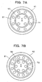
- Fig. 7A is a plan view showing the first modification example of an injection hole plate.
- the number of injection holes 71 formed in the injection hole plate 41 is 12; on the side closer to the center C, four of the injection holes 71 as an inner injection hole group are arranged with a uniform distance from the center C of the injection hole plate 41 in the circumferential direction; eight of the injection holes 71 as an outer injection hole group are arranged on the outer side of the inner injection hole group with a uniform distance from the center C of the injection hole plate 41 in the circumferential direction; an annular recessed portion 50 extending annularly is arranged between the inner injection hole group and the outer injection hole group; and an annular recessed portion 51 is arranged on the outer side of the outer injection hole group.
- Fig.7B is a plan view showing the second modification example of an injection hole plate.
- the number of the injection holes 72 formed in the injection hole plate 42 is increased to 18.
- the number of the injection holes 72 in the inner injection hole group is set to six and the number of the injection holes 72 in the outer injection hole group is set to 12.
- the two annular recessed portions 50, 51 are arranged.
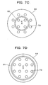
- Fig. 7C is a plan view showing the third modification example of an injection hole plate.
- the injection holes 73 are arranged in the injection hole plate 43 as with the first modification example.
- the annular recessed portion 50 is arranged only between the inner injection hole group and the outer injection hole group in the injection hole plate 43.
- Fig.7D is a plan view showing the fourth modification example of an injection hole plate.
- injection holes 74 are arranged in the injection hole plate 44 as with in the first modification example.
- the annular recessed portion 51 is arranged only on the outer side of the outer injection hole group in the injection hole plate 44.
- the recessed portion is annularly shaped and surrounds the injection holes, the effect of the recessed portion can be applied to all of the fuel moving toward the injection holes arranged closer to the center than the recessed portion.
- Fig.7E is a plan view showing the fifth modification example of an injection hole plate.
- 12 of injection holes 75 are arranged in the injection hole plate 45 as with the second modification example.
- the shape of the recessed portion is modified. That is, in the fifth modification example, the recessed portion is not annular, and divided recessed portions 55, 56 which intermittently extend in the circumferential direction as opposed to each of the injection holes 75 are arranged between the inner injection hole group and the outer injection hole group, and on the outer side of the outer injection hole group respectively.
- Fig.7F is a plan view showing the sixth modification example of an injection hole plate.
- the sixth modification example is similar to the fifth modification example, the sixth modification example is different from the fifth modification example in that the recessed portion arranged between the inner injection hole group and the outer injection hole group is the annular recessed portion 50 as with the first modification example, and the annular recessed portion 50 is formed in the injection hole plate 46.
- the number and arrangement of the injection holes 76 are the same as those in the fifth modification example.
- the divided recessed portion 56 arranged on the outer side of the outer injection hole group are divided at positions represented by broken lines except for portions opposed to each injection hole in the outer injection hole group, fuel led by the inner injection hole group passes through the divided portions and reaches the inner injection hole group through the divided recessed portion 55 or the annular recessed portion 50 without being affected by the divided recessed portion 56. Accordingly, since the effect of fuel atomization by the inner injection hole group is not less degraded than the effect by the outer injection hole group, the atomization effects of the inner injection hole group and the outer injection hole group can be made uniform.
- Fig.7G is a plan view showing the seventh modification example of an injection hole plate.
- 12 injection holes 77 are formed in the injection hole plate 47
- an elongated first recessed portion 57A is arranged in the injection hole plate 47 so as to be adjacent to each of the injection holes 77 included in the inner injection hole group
- a second recessed portion 57B is arranged in the injection hole plate 47 so as to be adjacent to each of the injection holes 77 included in the outer injection hole group.
- Each of the recessed portions 57A, 57B is oriented to the center C of the injection hole plate 47.
- each of the recessed portions 57A, 57B is oriented to the center C, the effects by the recessed portions 57A, 57B can be equally applied to each of the injection holes 77 formed in the injection hole plate 47. Since the first recessed portion 57A adjacent to each of the injection holes 77 in the inner injection hole group is shaped like an elongated rectangle having a longer radial length than a a width in the circumferential direction of the injection hole plate 47, it is possible to lead efficiently fuel into each of the injection holes 77 in the inner injection hole group existing away from the valve seat.
- Fig.7H is a plan view showing the eighth modification example of the injection hole plate.
- the eighth modification example is obtained by omitting the second recessed portions 57B adjacent to the outer injection hole group from the seventh modification example and forming the first recessed portions 57A adjacent to the inner injection hole group in the injection hole plate 48.
- the number and arrangement of the injection holes 78 are the same as those in the seventh modification example.
- Fig.7I is a plan view showing the ninth modification example of an injection hole plate.
- the ninth modification example is obtained by omitting the first recessed portions 57A adjacent to the inner injection hole group from the seventh modification example and forming the second recessed portions 57B adjacent to the outer injection hole group in the injection hole plate 49.
- the number and arrangement of the injection holes 79 are the same as those in the seventh modification example.
- the eighth and the ninth modification examples can perform the same effect as the seventh modification example.
- the recessed portion 57 may be shaped such that the width with respect to a circumferential direction of the injection hole plate 47 is gradually smaller as getting closer to the injection hole 77.
- the fuel entering the recessed portion 57 is gradually narrowed toward the injection hole as represented by an arrow, the fuel flow toward the injection hole 77 can be enforced. This increases a force of pressing the fuel onto the inner wall surface of the injection hole 77, which contributes to fuel thinning.
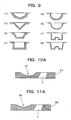
- the shape of the cross section of the recessed portion 57 which is orthogonal to the radial direction of the injection hole plate, can be variously modified as shown in (1) to (8) in Fig. 9.
- Fig. 9 shows possible shapes of the cross section of the recessed portion 57 as follows: (1) arc, (2) triangle, (3) trapezoid, (4) rectangle, (5) combination of rectangle and arc, (6) combination of trapezoid and arc, (7) protrusion portion formed in the bottom of rectangle and (8) protrusion portion formed in the bottom of trapezoid.
- cornered portions or angled portions may be rounded.
- the shape of the cross-section of the recessed portion which is parallel with the fuel flow direction (radial direction) and is perpendicular to the injection hole plate, is trapezoid having a flat bottom as shown in Fig. 2 , this is merely an example.
- the fuel flow direction toward the injection holes can be changed such that after passing through the valve seat, the fuel descends lower than a height of an inlet ports of the injection holes on the injection hole plate and then, turns to ascension and reaches the inlet ports of the injection holes, the recessed portion may be varied as described below.
- Fig.10A is an enlarged sectional view showing the first modification example of a recessed portion.
- a recessed portion 91 is formed in an injection hole plate 81, and the shape of cross section of the recessed portion 91 is arcuate.
- the arcuate portion may be a part of a circle, a part of an ellipse, a part of other curve or combination of them.
- Fig.10B is an enlarged sectional view showing Second modification example of a recessed portion.
- a recessed portion 92 is formed in an injection hole plate 82, and the shape of cross section of the recessed portion 92 is triangular. In this case, cornered portions or angled portions of the recessed portion 92 may be rounded.
- the straight portion is provided between the recessed portion and the injection holes.
- the existence/absence of the straight portion and the shape of the straight portion when viewed from the axial direction are optional and below-described variations are available.
- Fig.11A is a plan view showing the first modification example of the straight portion.
- a recessed portion 101 according to this modification example is formed in an injection hole plate 141 such that a contour P1 on a side of an injection hole 171 formed between an upper surface of the injection hole plate 141 and the recessed portion 101 conforms with an inlet port 181 of the injection hole 171.
- a length L1 of a straight portion 151 is uniform with respect to the circumferential direction of the inlet port 181. That is, the center C1 that provides the contour P matches the center of the injection hole 171.
- Fig.11B is a plan view showing the second modification example with respect to the straight portion.
- a recessed portion 102 according to this modification example is formed in an injection hole plate 142 such that a contour P2 on the side of an injection hole 172 formed between an upper surface of the injection hole plate 142 and the recessed portion 102 conforms to an inlet port 182 of the injection hole 172.
- a length L2 of a straight portion 152 is varied so as to be maximum at both ends and be minimum at the center with respect to a circumferential direction.
- the recessed portion 102 is formed such that the center C2 providing the contour P2 is located on a wall surface opposed to the injection hole 172.
- the contour of the recessed portion is configured to conform to the inlet port of the injection hole, when the fuel having passed through the recessed portion reaches the inlet port of the injection holes, the conditions with respect to the circumferential direction of the injection hole are almost same, and it is ensured that the fuel can be peeled.
- Fig.11C is a plan view showing the third modification example of the straight portion.
- This modification example is characterized by that, in order to eliminate the straight portion, a recessed portion 103 is formed in an injection hole plate 143 such that a boundary portion 110 between an upper surface of the injection hole plate 143 and the recessed portion 103 overlaps an inlet port 183 of an injection hole 173.
- a portion A where fuel peeling occurs becomes acute, that is, a peeling angle ⁇ 1 becomes large and an angle of the portion A ⁇ 2 becomes acute, fuel peeling is enhanced and fuel atomization is further improved.
- Fig.13A is an explanatory view showing the first example in which a plurality of recessed portions are provided with respect to one injection hole.
- a plurality of (three in this figure) recessed portions 105 are provided with respect to one injection hole 175, and each of the recessed portions 105 extends toward the injection hole 175.
- Fig.13B is an explanatory view showing the second example in which a plurality of recessed portions are provided with respect to one injection hole.
- the plurality of (two in this figure) recessed portions 106 are provided with respect to one injection hole 176 so as to extend toward the injection hole, and the recessed portions 106 are connected to each other on the side closer to the injection hole 176.
- fuel that does not flow toward the inlet port of the injection holes can be collected into the injection holes by the plurality of recessed portions. Because of this, fuel can be efficiently jetted.
- the orientation of the injection holes formed in the injection hole plate is not necessarily inclined relatively to the fuel advancing direction.
- the inclination angle ⁇ shown in Fig.2 may be 0, that is, the injection holes may be formed perpendicular to the injection hole plate.
Landscapes
- Engineering & Computer Science (AREA)
- Chemical & Material Sciences (AREA)
- Combustion & Propulsion (AREA)
- Mechanical Engineering (AREA)
- General Engineering & Computer Science (AREA)
- Physics & Mathematics (AREA)
- Electromagnetism (AREA)
- Fuel-Injection Apparatus (AREA)
Claims (17)
- Soupape d'injection de carburant (1C) comportant : une aiguille (3) logée dans un corps de soupape (2) dans un mouvement de va-et-vient ; une plaque à trous d'injection (32) fixée à une partie d'extrémité avant du corps de soupape, la plaque à trous d'injection (32) ayant au moins un trou d'injection (33) reliant un intérieur et un extérieur du corps de soupape (2) ; et un siège de soupape (6) auquel est fixée l'aiguille (3) et duquel est détachée cette dernière de manière à fermer ou ouvrir un trajet d'écoulement de carburant qui atteint le trou d'injection (33) dans la plaque à trous d'injection (32) à travers une circonférence extérieure de l'aiguille (3), où
la plaque à trous d'injection (32) comporte une partie évidée (15) dentée dans une direction axiale de l'aiguille (3) de manière à amener le carburant s'écoulant vers le trou d'injection (33) à travers le siège de soupape (6) à descendre plus bas qu'une hauteur d'un orifice d'entrée (35) du trou d'injection (33), puis, à remonter de manière à atteindre l'orifice d'entrée (35) du trou d'injection (33) sur la plaque à trous d'injection (32), où
le trou d'injection (33) de la plaque à trous d'injection (32) est à une position séparée d'un centre (C) vers l'extérieur dans la direction radiale par rapport à la plaque à trous d'injection (32),
caractérisée en ce que
le côté amont du trou d'injection (33) est partiellement découpé, ainsi l'orifice d'entrée (35) du trou d'injection (33) présente une différence d'altitude (ΔH) de façon à ce qu'un côté plus proche du centre (C) soit inférieur à un côté plus éloigné du centre (C). - Soupape d'injection de carburant (1C) selon la revendication 1, dans laquelle
la différence d'altitude (ΔH) est donnée en formant, sur la plaque à trous d'injection (32), une rainure (34) menant au trou d'injection (33) sur le côté le plus proche du centre (C). - Soupape d'injection de carburant (1C) selon la revendication 1 ou 2, dans laquelle
la partie évidée (15) est agencée de sorte qu'une partie limite (17) entre une surface supérieure de la plaque à trous d'injection (4) et la partie évidée (15) soit située sur une extension d'une surface de contact (25) entre le siège de soupape (6) et l'aiguille (3). - Soupape d'injection de carburant (1C) selon la revendication 3, dans laquelle
la partie évidée (15) a une surface de paroi latérale (23) qui relie la partie limite (17) à une partie inférieure (21), et la surface de contact (25) et la surface de paroi latérale (23) ont la même inclinaison l'une que l'autre. - Soupape d'injection de carburant (1C) selon l'une quelconque des revendications 1 à 4, dans laquelle
la partie évidée (15) et le trou d'injection (33) sont agencées dans la plaque à trous d'injection (32) en ayant une distance prédéterminée entre eux, et de ce fait une partie droite (26) est formée entre la partie évidée (15) et le trou d'injection (33). - Soupape d'injection de carburant (1C) selon l'une quelconque des revendications 1 à 5, dans laquelle
la plaque à trous d'injection (32) contient une pluralité de trous d'injection, et la partie évidée (15) s'étend dans la direction circonférentielle de la plaque à trous d'injection (32) de manière à entourer la pluralité de trous d'injection. - Soupape d'injection de carburant (1C) selon l'une quelconque des revendications 1 à 5, dans laquelle
la plaque à trous d'injection (45) contient un groupe de trous d'injection internes où une pluralité de trous d'injection (75) sont agencés dans la direction circonférentielle de la plaque à trous d'injection (45) et un groupe de trous d'injection externes où une pluralité de trous d'injection (75) sont agencés sur un côté extérieur du groupe de trous d'injection internes dans la direction circonférentielle, et
des premières parties évidées divisées (55) et des deuxièmes parties évidées divisées (56) sont pourvues en tant que partie évidée, où
les premières parties évidées divisées (55) sont agencées entre le groupe de trous d'injection internes et le groupe de trous d'injection externes de manière à s'étendre dans la direction circonférentielle de la plaque à trous d'injection (45), les premières parties évidées divisées (55) s'étendant par intermittence dans la direction circonférentielle tout en faisant face aux trous d'injection (75) dans le groupe de trous d'injections internes respectivement, et
les deuxièmes parties évidées divisées (56) sont agencées sur un côté extérieur du groupe de trous d'injection externes, les deuxièmes parties évidées divisées (56) s'étendant par intermittence dans la direction circonférentielle faisant face aux trous d'injection (75) dans le groupe de trous d'injection externes respectivement. - Soupape d'injection de carburant (1C) selon l'une quelconque des revendications 1 à 5, dans laquelle
la plaque à trous d'injection (46) contient un groupe de trous d'injection internes où une pluralité de trous d'injection (76) sont agencés dans la direction circonférentielle de la plaque à trous d'injection (46) et un groupe de trous d'injection externes où une pluralité de trous d'injection (76) sont agencés sur un côté extérieur du groupe de trous d'injection internes dans la direction circonférentielle, et
tout comme la partie évidée (50, 56), une partie évidée annulaire (50) est agencée entre le groupe de trous d'injection internes et le groupe de trous d'injection externes de manière à s'étendre dans la direction circonférentielle de la plaque à trous d'injection (46), et également
des parties évidées divisées (56) sont agencées sur un côté extérieur du groupe de trous d'injection externes, les parties évidées divisées (56) s'étendant par intermittence dans la direction circonférentielle faisant face aux trous d'injection (76) respectivement. - Soupape d'injection de carburant (1C) selon l'une quelconque des revendications 1 à 5, dans laquelle
la plaque à trous d'injection (47, 48) contient une pluralité de trous d'injection (77, 78), et la partie évidée (57A, 57B) est agencée de manière adjacente à chacun des trous d'injection (77, 78) et est orientée vers le centre (C) de la plaque à trous d'injection (47, 48). - Soupape d'injection de carburant (1C) selon l'une quelconque des revendications 1 à 5, dans laquelle
la partie évidée (57A) s'étend vers le centre (C) de la plaque à trous d'injection (47, 48) de manière à avoir une longueur radiale supérieure à une largeur dans la direction circonférentielle de la plaque à trous d'injection (47, 48). - Soupape d'injection de carburant (1C) selon l'une quelconque des revendications 1 à 10, dans laquelle
une partie en saillie (31) est formée sur l'aiguille (3), la partie en saillie (31) faisant face à la partie évidée (15) et faisant saillie sur un côté se rapprochant de la plaque à trous d'injection. - Soupape d'injection de carburant (1C) selon la revendication 11, dans laquelle
la partie en saillie (15) a la même forme que la partie évidée en vis à vis (15). - Soupape d'injection de carburant (1C) selon l'une quelconque des revendications 1 à 5, dans laquelle
la partie évidée (101) est formée dans la plaque à trous d'injection (141) de sorte qu'un contour (P1) de la partie évidée (101) sur un côté du trou d'injection (171) formé entre la partie évidée (101) et la surface supérieure de la plaque à trous d'injection (141) soit conforme à un orifice d'entrée (181) du trou d'injection (171). - Soupape d'injection de carburant (1C) selon l'une quelconque des revendications 1 à 5, dans laquelle
la partie évidée (57) est formée dans la plaque à trous d'injection (47) de sorte qu'une largeur (W) par rapport à la direction circonférentielle de la plaque à trous d'injection (47) diminue progressivement à mesure que la largeur se rapproche du trou d'injection. - Soupape d'injection de carburant (1C) selon l'une quelconque des revendications 1 à 5, dans laquelle
une pluralité de parties évidées (105) par rapport à un trou d'injection (175) sont formées dans la plaque à trous d'injection, et chacune de la pluralité de parties évidées (105) s'étend vers les trous d'injection (175). - Soupape d'injection de carburant (1C) selon la revendication 15, dans laquelle
la pluralité de parties évidées (106) sont reliées les unes aux autres sur un côté plus proche du trou d'injection (176). - Soupape d'injection de carburant (1C) selon la revendication 1 ou 2, dans laquelle
la partie évidée (103) est formée dans la plaque à trous d'injection (143) de telle sorte qu'une partie limite (110) entre une surface supérieure de la plaque à trous d'injection (143) et la partie évidée (103) chevauche l'orifice d'entrée (183) du trou d'injection (173).
Applications Claiming Priority (1)
| Application Number | Priority Date | Filing Date | Title |
|---|---|---|---|
| PCT/JP2010/053679 WO2011108118A1 (fr) | 2010-03-05 | 2010-03-05 | Soupape d'injection de carburant |
Publications (3)
| Publication Number | Publication Date |
|---|---|
| EP2543872A1 EP2543872A1 (fr) | 2013-01-09 |
| EP2543872A4 EP2543872A4 (fr) | 2013-06-05 |
| EP2543872B1 true EP2543872B1 (fr) | 2014-04-30 |
Family
ID=44541802
Family Applications (1)
| Application Number | Title | Priority Date | Filing Date |
|---|---|---|---|
| EP10847020.4A Not-in-force EP2543872B1 (fr) | 2010-03-05 | 2010-03-05 | Soupape d'injection de carburant |
Country Status (5)
| Country | Link |
|---|---|
| US (1) | US8794550B2 (fr) |
| EP (1) | EP2543872B1 (fr) |
| JP (1) | JP5299557B2 (fr) |
| CN (1) | CN102906414B (fr) |
| WO (1) | WO2011108118A1 (fr) |
Families Citing this family (7)
| Publication number | Priority date | Publication date | Assignee | Title |
|---|---|---|---|---|
| KR101670154B1 (ko) * | 2012-08-09 | 2016-10-27 | 미쓰비시덴키 가부시키가이샤 | 연료 분사 밸브 |
| US9470197B2 (en) * | 2012-12-21 | 2016-10-18 | Caterpillar Inc. | Fuel injector having turbulence-reducing sac |
| JP2016205197A (ja) * | 2015-04-21 | 2016-12-08 | 日立オートモティブシステムズ株式会社 | 燃料噴射装置 |
| US10724486B2 (en) * | 2018-03-21 | 2020-07-28 | Delphi Technologies Ip Limited | Fluid injector having a director plate |
| JP7167663B2 (ja) * | 2018-11-28 | 2022-11-09 | 株式会社デンソー | 燃料噴射弁 |
| JP7272645B2 (ja) * | 2019-06-20 | 2023-05-12 | 株式会社デンソー | 燃料噴射弁 |
| CN114522817A (zh) * | 2022-04-21 | 2022-05-24 | 山西海普瑞科技有限公司 | 一种用于防止高压水射流破坏的喷嘴结构 |
Family Cites Families (18)
| Publication number | Priority date | Publication date | Assignee | Title |
|---|---|---|---|---|
| US5383597A (en) * | 1993-08-06 | 1995-01-24 | Ford Motor Company | Apparatus and method for controlling the cone angle of an atomized spray from a low pressure fuel injector |
| JP3156554B2 (ja) | 1995-07-24 | 2001-04-16 | トヨタ自動車株式会社 | 燃料噴射弁 |
| JP3847564B2 (ja) * | 2001-01-30 | 2006-11-22 | 株式会社日立製作所 | 燃料噴射弁 |
| US6817545B2 (en) * | 2002-01-09 | 2004-11-16 | Visteon Global Technologies, Inc. | Fuel injector nozzle assembly |
| JP4072402B2 (ja) * | 2002-09-06 | 2008-04-09 | 株式会社日立製作所 | 燃料噴射弁およびそれを搭載した内燃機関 |
| EP1581737B1 (fr) | 2003-01-09 | 2009-05-27 | Continental Automotive Systems US, Inc. | Regulation de la repartition de la pulverisation avec des orifices non inclines formes sur un disque de dosage d'injection en carburant a collerette dote d'un reducteur de volume de sac |
| JP2005155547A (ja) * | 2003-11-27 | 2005-06-16 | Mitsubishi Electric Corp | 燃料噴射弁 |
| JP2005282420A (ja) | 2004-03-29 | 2005-10-13 | Denso Corp | 燃料噴射弁 |
| US7198207B2 (en) * | 2004-11-05 | 2007-04-03 | Visteon Global Technologies, Inc. | Low pressure fuel injector nozzle |
| US7124963B2 (en) * | 2004-11-05 | 2006-10-24 | Visteon Global Technologies, Inc. | Low pressure fuel injector nozzle |
| JP4315115B2 (ja) * | 2005-03-10 | 2009-08-19 | 株式会社デンソー | 燃料噴射弁 |
| JP2007182767A (ja) * | 2006-01-05 | 2007-07-19 | Hitachi Ltd | 燃料噴射弁 |
| DE602006007674D1 (de) | 2006-02-03 | 2009-08-20 | Continental Automotive Gmbh | Düsenanordnung für eine Einspritzdüse und Einspritzdüse |
| JP4218696B2 (ja) | 2006-05-19 | 2009-02-04 | トヨタ自動車株式会社 | 燃料噴射ノズル |
| JP4636004B2 (ja) | 2006-11-10 | 2011-02-23 | トヨタ自動車株式会社 | 内燃機関の燃料噴射弁 |
| EP2484890B8 (fr) | 2007-03-27 | 2015-05-06 | Mitsubishi Electric Corporation | Injecteur de carburant |
| US20090057446A1 (en) | 2007-08-29 | 2009-03-05 | Visteon Global Technologies, Inc. | Low pressure fuel injector nozzle |
| US20090090794A1 (en) | 2007-10-04 | 2009-04-09 | Visteon Global Technologies, Inc. | Low pressure fuel injector |
-
2010
- 2010-03-05 WO PCT/JP2010/053679 patent/WO2011108118A1/fr not_active Ceased
- 2010-03-05 EP EP10847020.4A patent/EP2543872B1/fr not_active Not-in-force
- 2010-03-05 CN CN201080063742.9A patent/CN102906414B/zh not_active Expired - Fee Related
- 2010-03-05 US US13/578,908 patent/US8794550B2/en active Active
- 2010-03-05 JP JP2012502953A patent/JP5299557B2/ja not_active Expired - Fee Related
Also Published As
| Publication number | Publication date |
|---|---|
| CN102906414A (zh) | 2013-01-30 |
| EP2543872A1 (fr) | 2013-01-09 |
| CN102906414B (zh) | 2015-07-15 |
| JP5299557B2 (ja) | 2013-09-25 |
| WO2011108118A1 (fr) | 2011-09-09 |
| EP2543872A4 (fr) | 2013-06-05 |
| JPWO2011108118A1 (ja) | 2013-06-20 |
| US8794550B2 (en) | 2014-08-05 |
| US20120305678A1 (en) | 2012-12-06 |
Similar Documents
| Publication | Publication Date | Title |
|---|---|---|
| EP2543872B1 (fr) | Soupape d'injection de carburant | |
| JP4022882B2 (ja) | 燃料噴射装置 | |
| CN101449050B (zh) | 燃料喷嘴 | |
| JP5772495B2 (ja) | 燃料噴射弁 | |
| JP5855270B2 (ja) | 燃料噴射弁 | |
| US7703707B2 (en) | Fuel injector | |
| CN102444511B (zh) | 燃料喷射阀 | |
| CN102465805A (zh) | 燃料喷射阀 | |
| JP2013007316A (ja) | 燃料噴射弁 | |
| JP2011506849A (ja) | 燃料噴射弁 | |
| JP5277056B2 (ja) | 燃料噴射弁 | |
| JP4646256B2 (ja) | 燃料噴射弁 | |
| JP2015025406A (ja) | 燃料噴射弁 | |
| EP2749762B1 (fr) | Soupape d'injection de carburant | |
| CN104033303A (zh) | 燃料喷射阀 | |
| JP6392689B2 (ja) | 燃料噴射弁 | |
| JP5838701B2 (ja) | 燃料噴射弁 | |
| KR20040077933A (ko) | 연료 분사 밸브 | |
| JP2003184706A (ja) | 燃料噴射弁 | |
| US20140027541A1 (en) | Fuel Injection Valve | |
| JP4537457B2 (ja) | 燃料噴射弁 | |
| JP6501500B2 (ja) | 燃料噴射弁 | |
| JP3730951B2 (ja) | 燃料噴射弁 | |
| EP3156640B1 (fr) | Corps de buse pour un injecteur de fluide et injecteur de fluide | |
| JP2002054532A (ja) | 燃料噴射弁 |
Legal Events
| Date | Code | Title | Description |
|---|---|---|---|
| PUAI | Public reference made under article 153(3) epc to a published international application that has entered the european phase |
Free format text: ORIGINAL CODE: 0009012 |
|
| 17P | Request for examination filed |
Effective date: 20120813 |
|
| AK | Designated contracting states |
Kind code of ref document: A1 Designated state(s): AT BE BG CH CY CZ DE DK EE ES FI FR GB GR HR HU IE IS IT LI LT LU LV MC MK MT NL NO PL PT RO SE SI SK SM TR |
|
| RAP1 | Party data changed (applicant data changed or rights of an application transferred) |
Owner name: TOYOTA JIDOSHA KABUSHIKI KAISHA |
|
| A4 | Supplementary search report drawn up and despatched |
Effective date: 20130508 |
|
| RIC1 | Information provided on ipc code assigned before grant |
Ipc: F02M 61/18 20060101AFI20130502BHEP |
|
| DAX | Request for extension of the european patent (deleted) | ||
| GRAP | Despatch of communication of intention to grant a patent |
Free format text: ORIGINAL CODE: EPIDOSNIGR1 |
|
| INTG | Intention to grant announced |
Effective date: 20140107 |
|
| RIN1 | Information on inventor provided before grant (corrected) |
Inventor name: KUROKAWA, TOSHIKUNI Inventor name: KANEKO, NAOYA Inventor name: SAKAI, HIROYUKI Inventor name: SHIMIZU, NOBUYUKI |
|
| GRAS | Grant fee paid |
Free format text: ORIGINAL CODE: EPIDOSNIGR3 |
|
| GRAA | (expected) grant |
Free format text: ORIGINAL CODE: 0009210 |
|
| AK | Designated contracting states |
Kind code of ref document: B1 Designated state(s): AT BE BG CH CY CZ DE DK EE ES FI FR GB GR HR HU IE IS IT LI LT LU LV MC MK MT NL NO PL PT RO SE SI SK SM TR |
|
| REG | Reference to a national code |
Ref country code: CH Ref legal event code: EP Ref country code: GB Ref legal event code: FG4D |
|
| REG | Reference to a national code |
Ref country code: AT Ref legal event code: REF Ref document number: 665324 Country of ref document: AT Kind code of ref document: T Effective date: 20140515 |
|
| REG | Reference to a national code |
Ref country code: IE Ref legal event code: FG4D |
|
| REG | Reference to a national code |
Ref country code: DE Ref legal event code: R096 Ref document number: 602010015731 Country of ref document: DE Effective date: 20140612 |
|
| REG | Reference to a national code |
Ref country code: AT Ref legal event code: MK05 Ref document number: 665324 Country of ref document: AT Kind code of ref document: T Effective date: 20140430 |
|
| REG | Reference to a national code |
Ref country code: LT Ref legal event code: MG4D |
|
| REG | Reference to a national code |
Ref country code: NL Ref legal event code: VDEP Effective date: 20140430 |
|
| PG25 | Lapsed in a contracting state [announced via postgrant information from national office to epo] |
Ref country code: LT Free format text: LAPSE BECAUSE OF FAILURE TO SUBMIT A TRANSLATION OF THE DESCRIPTION OR TO PAY THE FEE WITHIN THE PRESCRIBED TIME-LIMIT Effective date: 20140430 Ref country code: FI Free format text: LAPSE BECAUSE OF FAILURE TO SUBMIT A TRANSLATION OF THE DESCRIPTION OR TO PAY THE FEE WITHIN THE PRESCRIBED TIME-LIMIT Effective date: 20140430 Ref country code: BG Free format text: LAPSE BECAUSE OF FAILURE TO SUBMIT A TRANSLATION OF THE DESCRIPTION OR TO PAY THE FEE WITHIN THE PRESCRIBED TIME-LIMIT Effective date: 20140730 Ref country code: NO Free format text: LAPSE BECAUSE OF FAILURE TO SUBMIT A TRANSLATION OF THE DESCRIPTION OR TO PAY THE FEE WITHIN THE PRESCRIBED TIME-LIMIT Effective date: 20140730 Ref country code: CY Free format text: LAPSE BECAUSE OF FAILURE TO SUBMIT A TRANSLATION OF THE DESCRIPTION OR TO PAY THE FEE WITHIN THE PRESCRIBED TIME-LIMIT Effective date: 20140430 Ref country code: NL Free format text: LAPSE BECAUSE OF FAILURE TO SUBMIT A TRANSLATION OF THE DESCRIPTION OR TO PAY THE FEE WITHIN THE PRESCRIBED TIME-LIMIT Effective date: 20140430 Ref country code: GR Free format text: LAPSE BECAUSE OF FAILURE TO SUBMIT A TRANSLATION OF THE DESCRIPTION OR TO PAY THE FEE WITHIN THE PRESCRIBED TIME-LIMIT Effective date: 20140731 Ref country code: IS Free format text: LAPSE BECAUSE OF FAILURE TO SUBMIT A TRANSLATION OF THE DESCRIPTION OR TO PAY THE FEE WITHIN THE PRESCRIBED TIME-LIMIT Effective date: 20140830 |
|
| PG25 | Lapsed in a contracting state [announced via postgrant information from national office to epo] |
Ref country code: SE Free format text: LAPSE BECAUSE OF FAILURE TO SUBMIT A TRANSLATION OF THE DESCRIPTION OR TO PAY THE FEE WITHIN THE PRESCRIBED TIME-LIMIT Effective date: 20140430 Ref country code: HR Free format text: LAPSE BECAUSE OF FAILURE TO SUBMIT A TRANSLATION OF THE DESCRIPTION OR TO PAY THE FEE WITHIN THE PRESCRIBED TIME-LIMIT Effective date: 20140430 Ref country code: AT Free format text: LAPSE BECAUSE OF FAILURE TO SUBMIT A TRANSLATION OF THE DESCRIPTION OR TO PAY THE FEE WITHIN THE PRESCRIBED TIME-LIMIT Effective date: 20140430 Ref country code: ES Free format text: LAPSE BECAUSE OF FAILURE TO SUBMIT A TRANSLATION OF THE DESCRIPTION OR TO PAY THE FEE WITHIN THE PRESCRIBED TIME-LIMIT Effective date: 20140430 Ref country code: PL Free format text: LAPSE BECAUSE OF FAILURE TO SUBMIT A TRANSLATION OF THE DESCRIPTION OR TO PAY THE FEE WITHIN THE PRESCRIBED TIME-LIMIT Effective date: 20140430 Ref country code: LV Free format text: LAPSE BECAUSE OF FAILURE TO SUBMIT A TRANSLATION OF THE DESCRIPTION OR TO PAY THE FEE WITHIN THE PRESCRIBED TIME-LIMIT Effective date: 20140430 |
|
| REG | Reference to a national code |
Ref country code: DE Ref legal event code: R084 Ref document number: 602010015731 Country of ref document: DE |
|
| PG25 | Lapsed in a contracting state [announced via postgrant information from national office to epo] |
Ref country code: PT Free format text: LAPSE BECAUSE OF FAILURE TO SUBMIT A TRANSLATION OF THE DESCRIPTION OR TO PAY THE FEE WITHIN THE PRESCRIBED TIME-LIMIT Effective date: 20140901 |
|
| PG25 | Lapsed in a contracting state [announced via postgrant information from national office to epo] |
Ref country code: RO Free format text: LAPSE BECAUSE OF FAILURE TO SUBMIT A TRANSLATION OF THE DESCRIPTION OR TO PAY THE FEE WITHIN THE PRESCRIBED TIME-LIMIT Effective date: 20140430 Ref country code: EE Free format text: LAPSE BECAUSE OF FAILURE TO SUBMIT A TRANSLATION OF THE DESCRIPTION OR TO PAY THE FEE WITHIN THE PRESCRIBED TIME-LIMIT Effective date: 20140430 Ref country code: DK Free format text: LAPSE BECAUSE OF FAILURE TO SUBMIT A TRANSLATION OF THE DESCRIPTION OR TO PAY THE FEE WITHIN THE PRESCRIBED TIME-LIMIT Effective date: 20140430 Ref country code: SK Free format text: LAPSE BECAUSE OF FAILURE TO SUBMIT A TRANSLATION OF THE DESCRIPTION OR TO PAY THE FEE WITHIN THE PRESCRIBED TIME-LIMIT Effective date: 20140430 Ref country code: BE Free format text: LAPSE BECAUSE OF FAILURE TO SUBMIT A TRANSLATION OF THE DESCRIPTION OR TO PAY THE FEE WITHIN THE PRESCRIBED TIME-LIMIT Effective date: 20140430 Ref country code: CZ Free format text: LAPSE BECAUSE OF FAILURE TO SUBMIT A TRANSLATION OF THE DESCRIPTION OR TO PAY THE FEE WITHIN THE PRESCRIBED TIME-LIMIT Effective date: 20140430 |
|
| REG | Reference to a national code |
Ref country code: DE Ref legal event code: R097 Ref document number: 602010015731 Country of ref document: DE |
|
| REG | Reference to a national code |
Ref country code: DE Ref legal event code: R084 Ref document number: 602010015731 Country of ref document: DE Effective date: 20141219 |
|
| PLBE | No opposition filed within time limit |
Free format text: ORIGINAL CODE: 0009261 |
|
| STAA | Information on the status of an ep patent application or granted ep patent |
Free format text: STATUS: NO OPPOSITION FILED WITHIN TIME LIMIT |
|
| PG25 | Lapsed in a contracting state [announced via postgrant information from national office to epo] |
Ref country code: IT Free format text: LAPSE BECAUSE OF FAILURE TO SUBMIT A TRANSLATION OF THE DESCRIPTION OR TO PAY THE FEE WITHIN THE PRESCRIBED TIME-LIMIT Effective date: 20140430 |
|
| 26N | No opposition filed |
Effective date: 20150202 |
|
| REG | Reference to a national code |
Ref country code: DE Ref legal event code: R097 Ref document number: 602010015731 Country of ref document: DE Effective date: 20150202 |
|
| PG25 | Lapsed in a contracting state [announced via postgrant information from national office to epo] |
Ref country code: SI Free format text: LAPSE BECAUSE OF FAILURE TO SUBMIT A TRANSLATION OF THE DESCRIPTION OR TO PAY THE FEE WITHIN THE PRESCRIBED TIME-LIMIT Effective date: 20140430 |
|
| PG25 | Lapsed in a contracting state [announced via postgrant information from national office to epo] |
Ref country code: MC Free format text: LAPSE BECAUSE OF FAILURE TO SUBMIT A TRANSLATION OF THE DESCRIPTION OR TO PAY THE FEE WITHIN THE PRESCRIBED TIME-LIMIT Effective date: 20140430 Ref country code: LU Free format text: LAPSE BECAUSE OF FAILURE TO SUBMIT A TRANSLATION OF THE DESCRIPTION OR TO PAY THE FEE WITHIN THE PRESCRIBED TIME-LIMIT Effective date: 20150305 |
|
| REG | Reference to a national code |
Ref country code: CH Ref legal event code: PL |
|
| GBPC | Gb: european patent ceased through non-payment of renewal fee |
Effective date: 20150305 |
|
| REG | Reference to a national code |
Ref country code: FR Ref legal event code: ST Effective date: 20151130 |
|
| REG | Reference to a national code |
Ref country code: IE Ref legal event code: MM4A |
|
| PG25 | Lapsed in a contracting state [announced via postgrant information from national office to epo] |
Ref country code: CH Free format text: LAPSE BECAUSE OF NON-PAYMENT OF DUE FEES Effective date: 20150331 Ref country code: LI Free format text: LAPSE BECAUSE OF NON-PAYMENT OF DUE FEES Effective date: 20150331 Ref country code: GB Free format text: LAPSE BECAUSE OF NON-PAYMENT OF DUE FEES Effective date: 20150305 Ref country code: IE Free format text: LAPSE BECAUSE OF NON-PAYMENT OF DUE FEES Effective date: 20150305 |
|
| PG25 | Lapsed in a contracting state [announced via postgrant information from national office to epo] |
Ref country code: FR Free format text: LAPSE BECAUSE OF NON-PAYMENT OF DUE FEES Effective date: 20150331 |
|
| PG25 | Lapsed in a contracting state [announced via postgrant information from national office to epo] |
Ref country code: MT Free format text: LAPSE BECAUSE OF FAILURE TO SUBMIT A TRANSLATION OF THE DESCRIPTION OR TO PAY THE FEE WITHIN THE PRESCRIBED TIME-LIMIT Effective date: 20140430 |
|
| PG25 | Lapsed in a contracting state [announced via postgrant information from national office to epo] |
Ref country code: HU Free format text: LAPSE BECAUSE OF FAILURE TO SUBMIT A TRANSLATION OF THE DESCRIPTION OR TO PAY THE FEE WITHIN THE PRESCRIBED TIME-LIMIT; INVALID AB INITIO Effective date: 20100305 Ref country code: SM Free format text: LAPSE BECAUSE OF FAILURE TO SUBMIT A TRANSLATION OF THE DESCRIPTION OR TO PAY THE FEE WITHIN THE PRESCRIBED TIME-LIMIT Effective date: 20140430 |
|
| PG25 | Lapsed in a contracting state [announced via postgrant information from national office to epo] |
Ref country code: TR Free format text: LAPSE BECAUSE OF FAILURE TO SUBMIT A TRANSLATION OF THE DESCRIPTION OR TO PAY THE FEE WITHIN THE PRESCRIBED TIME-LIMIT Effective date: 20140430 |
|
| PG25 | Lapsed in a contracting state [announced via postgrant information from national office to epo] |
Ref country code: MK Free format text: LAPSE BECAUSE OF FAILURE TO SUBMIT A TRANSLATION OF THE DESCRIPTION OR TO PAY THE FEE WITHIN THE PRESCRIBED TIME-LIMIT Effective date: 20140430 |
|
| PGFP | Annual fee paid to national office [announced via postgrant information from national office to epo] |
Ref country code: DE Payment date: 20210224 Year of fee payment: 12 |
|
| REG | Reference to a national code |
Ref country code: DE Ref legal event code: R119 Ref document number: 602010015731 Country of ref document: DE |
|
| PG25 | Lapsed in a contracting state [announced via postgrant information from national office to epo] |
Ref country code: DE Free format text: LAPSE BECAUSE OF NON-PAYMENT OF DUE FEES Effective date: 20221001 |