EP2543912B1 - Dispositif d'étanchéité - Google Patents
Dispositif d'étanchéité Download PDFInfo
- Publication number
- EP2543912B1 EP2543912B1 EP11750411.8A EP11750411A EP2543912B1 EP 2543912 B1 EP2543912 B1 EP 2543912B1 EP 11750411 A EP11750411 A EP 11750411A EP 2543912 B1 EP2543912 B1 EP 2543912B1
- Authority
- EP
- European Patent Office
- Prior art keywords
- ring
- sealing
- seal ring
- contact
- backup
- Prior art date
- Legal status (The legal status is an assumption and is not a legal conclusion. Google has not performed a legal analysis and makes no representation as to the accuracy of the status listed.)
- Active
Links
Images

Classifications
-
- F—MECHANICAL ENGINEERING; LIGHTING; HEATING; WEAPONS; BLASTING
- F16—ENGINEERING ELEMENTS AND UNITS; GENERAL MEASURES FOR PRODUCING AND MAINTAINING EFFECTIVE FUNCTIONING OF MACHINES OR INSTALLATIONS; THERMAL INSULATION IN GENERAL
- F16J—PISTONS; CYLINDERS; SEALINGS
- F16J15/00—Sealings
- F16J15/16—Sealings between relatively-moving surfaces
- F16J15/32—Sealings between relatively-moving surfaces with elastic sealings, e.g. O-rings
- F16J15/3204—Sealings between relatively-moving surfaces with elastic sealings, e.g. O-rings with at least one lip
- F16J15/3208—Sealings between relatively-moving surfaces with elastic sealings, e.g. O-rings with at least one lip provided with tension elements, e.g. elastic rings
-
- F—MECHANICAL ENGINEERING; LIGHTING; HEATING; WEAPONS; BLASTING
- F16—ENGINEERING ELEMENTS AND UNITS; GENERAL MEASURES FOR PRODUCING AND MAINTAINING EFFECTIVE FUNCTIONING OF MACHINES OR INSTALLATIONS; THERMAL INSULATION IN GENERAL
- F16J—PISTONS; CYLINDERS; SEALINGS
- F16J15/00—Sealings
- F16J15/16—Sealings between relatively-moving surfaces
Definitions
- the present invention relates to a sealing apparatus provided at a rotating portion of various machines such a machining tool or a construction machine, and particularly relates to a sealing apparatus having an improved sealing performance for a rotating part which is subject to a high fluid pressure and rotates with a low torque.
- a sealing apparatus in which, in order to seal an annular gap S formed between two inner and outer members 11 and 12 that coaxially rotate relative to each other, an O-ring (backup ring) 14 and a seal ring 15 fitted on its inner side are installed in an annular groove for sealing 13 which is formed on an inner surface portion of a shaft hole 11a of a first member (outer member) 11 along a peripheral direction, and inclined faces 15a, 15b are formed in a sliding surface of the seal ring 15 against a second member (inner member) 12 at both sides in an axial direction (a direction in which a fluid pressure P is applied).
- an O-ring (backup ring) 14 and a seal ring 15 fitted on its inner side are installed in an annular groove for sealing 13 which is formed on an inner surface portion of a shaft hole 11a of a first member (outer member) 11 along a peripheral direction, and inclined faces 15a, 15b are formed in a sliding surface of the seal ring 15 against a second member (inner member) 12 at
- Patent Document 1 Japanese Laid-Open Patent Application No. 2005-504237
- An object of the present invention is to provide a sealing apparatus which can always exhibit a stable and high sealing performance while achieving a reduction in the torque of the rotation portion, even when a high fluid pressure is applied.
- a sealing apparatus for sealing an annular gap formed between two inner and outer members that coaxially rotate relative to each other which includes a backup ring provided in contact with a bottom surface of an annular groove for sealing, the annular groove for sealing being formed along a peripheral direction in one of the members and having a rectangular cross section, and a seal ring provided on an opening side of the annual groove for sealing, the seal ring being in sliding contact with the other member through an entire periphery by being pressed by the backup ring and rotationally slidable relative to the other member, a contact surface of the backup ring against the bottom surface being a surface having a cylindrical shape and a contact surface of the backup ring against the seal ring being a toric convex surface having a constant radius of curvature in an axial direction, a contact surface of the seal ring against the backup ring being a surface having a cylindrical shape and a contact surface of the seal ring against the other member being a
- Exemplary two inner and outer members that coaxially rotate relative to each other are a shaft and a housing.
- a seal ring is installed at an inner peripheral side of the backup ring and slides on (an outer peripheral surface of) a shaft by being subject to a radially inward pressing force exerted by the backup ring.
- the seal ring is provided on the outer peripheral side of the backup ring and slides on (an inner peripheral surface of) the housing by being subject to a radially outward pressing force exerted by the backup ring.
- the backup ring and the seal ring are pressed against a side surface of the annual groove for sealing, which is formed in one of the members, on an opposite pressure side, i.e., on a side where it does not come into contact with the operating fluid. Also, the backup ring is subject to an elastic compression due to the operating fluid pressure and presses the seal ring towards the other member side by an elastic restoring force thereof.
- the seal ring is configured in such a manner that its contact surface against the backup ring is a surface having a cylindrical shape and its contact surface against the other member is a toric convex surface having a constant radius of curvature in an axial direction, the seal ring inclines by being subject to the operating fluid pressure and the pressing force by the backup ring and causes its end surface on the opposite pressure side to come into surface contact with a side surface on the opposite pressure side of the annual groove for sealing, and stabilizes at a position where an opposite pressure side portion of the inner peripheral side comes into surface contact with the other member.
- the contact surface of the back ring against the bottom surface of the annual groove for sealing is a surface having a cylindrical shape, even when a high operating fluid pressure is applied, the operating fluid is not allowed to enter between the backup ring and the bottom surface of the annual groove for sealing, the entire contact surface of the backup ring against the bottom surface of the annual groove for sealing always remains in contact with the bottom surface of the annual groove for sealing.
- both the bottom surface of the annual groove for sealing and the contact surface of the backup ring against such bottom surface are surfaces each having a cylindrical shape, no gap is produced between the two surfaces. Therefore, with the elastic restoring force of the backup ring being always effectively acting as a pressure force that urges the seal ring towards the other member side, a stable sealing performance can be always achieved.
- the backup ring is a D-ring made of rubber
- the seal ring is a resin ring made of one of polyethylene and polyamide.
- the seal ring By employing a D-ring made of rubber as the backup ring, the seal ring can be inclined while applying a moderate pressure force due to rubber elasticity to the seal ring.
- a resin ring made of polyethylene or polyamide as a seal ring, a wear of the D-ring made of rubber due to friction between the two rings can be minimized while maintaining a durability of the seal ring against a high fluid pressure and a slidability against the other member.
- an end surface of the seal ring has a tapered face which inclines in such a manner that a distance from a side surface of the annual groove for sealing becomes larger towards the bottom surface of the annual groove for sealing.
- a stable sealing performance can be always achieved by always effectively applying an elastic restoring force of the backup ring as a pressing force that urges the seal ring, and a reduced torque of the rotation portion can be achieved by reducing a frictional resistance by the seal ring.
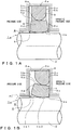
- a sealing apparatus of the present embodiment is applicable to a rotating portion of a hydraulic machining device and the like, and, as shown in Fig. 1A , seals an annular gap S formed between a housing (one member) 1 and a cylindrical shaft (the other member) 2 inserted through a shaft hole 1a in the housing 1 while allowing a relative rotation between the two members 1 and 2.
- This sealing apparatus has a D-ring (backup ring) and a seal ring 4. Both rings 3 and 4 are installed in an annular groove for sealing 5 that has a rectangular cross section and formed in an inner surface portion of the shaft hole 1a along a peripheral direction.
- the D-ring 3 is provided in contact with a bottom surface 5a of the annual groove for sealing 5.
- the D-ring 3 is a sealing member made of rubber and having a substantially D-shaped cross section, with its outer peripheral surface 3a being a surface having a cylindrical shape similar to the bottom surface 5a of the annual groove for sealing 5 and its inner peripheral surface 3b being a toric convex surface having a constant radius of curvature in an axial direction.
- the seal ring 4 is a sealing member made of resin of polyethylene or polyamide, with its outer peripheral surface 4a being a surface having a cylindrical shape and its inner peripheral surface 4b being a toric convex surface having a constant radius of curvature in the axial direction.
- An axial-direction radius of curvature of the inner peripheral surface 4b of the seal ring 4 is selected to be smaller than an axial-direction radius of curvature of the inner peripheral surface 3b of the D-ring 3.
- the seal ring 4 is provided in a tightly fit manner against the inner peripheral surface 3b of the backup ring 3 through an entire periphery, and rotationally slide relatively while being tightly pressed in contact with an entire periphery of an outer peripheral surface of the shaft 2.
- An inner diameter size of the D-ring 3 is substantially equal to an outer diameter size of the seal ring 4, and the D-ring 3 and the seal ring 4 are installed in the annual groove for sealing 5 in a state where they are in close contact with each other.
- the D-ring 3 When installed, the D-ring 3 is interposed between the seal ring 4 and the bottom surface 5a of the annual groove for sealing 5, and compressed in a radial direction.
- An elastic restoring force of the D-ring 3 acts as a pressing force that urges the seal ring 4 towards the shaft 2.
- tapered faces 4c and 4d are formed in such a manner that a distance from a side surface 5b of the groove 5 becomes larger as towards the bottom surface 5a of the annual groove for sealing 5.
- the seal ring 4 Since the seal ring 4 is configured in such a manner that its outer peripheral surface 4a is a surface having a cylindrical shape whereas its inner peripheral surface 4b is a toric convex surface having a constant radius of curvature in the axial direction, the seal ring 4 inclines by being subject to the hydraulic pressure P and the pressing force by the D-ring 3, and stabilizes at a position where an entirety of the tapered face 4c on the opposite pressure side is in surface contact with the side surface 5b on the opposite pressure side of the annual groove for sealing 5.
- the inner peripheral surface 4b of the seal ring 4 which is in contact with the shaft 2 is a toric convex surface having a constant radius of curvature in an axial direction, and by selecting this radius of curvature to be smaller than the axial-direction radius of curvature of the inner peripheral surface 3b of the D-ring 3, an inclining movement of the seal ring 4 to a stable position, which is caused by being subject to the hydraulic pressure P and the pressing force of the D-ring 3, is performed smoothly in a non-stepped manner.
- the outer peripheral surface 3a of the D-ring 3 is a surface having a cylindrical shape, the operating oil is not allowed to enter between the D-ring 3 and the bottom surface 5a of the annual groove for sealing 5 even when the hydraulic pressure P is being applied, an entirety of the outer peripheral surface 3a of the D-ring 3 always remains in contact with the bottom surface 5a of the annual groove for sealing 5. Therefore, by always effectively causing the elastic recovering force of the D-ring 3 to act as the pressing force that urges the seal ring 4 towards the shaft 2, a stable sealing performance can be always achieved.
- a ring made of resin of polyethylene or polyamide is employed as the seal ring 4
- a wear of the D-ring 3 made of rubber due to the friction between the rings 3 and 4 can be minimized, and a durability of the seal ring 4 against a high fluid pressure and a slidability with respect to the shaft 2 can be ensured.
- this sealing apparatus can be preferably used for the rotating portion of the hydraulic apparatus in which a direction of action of the hydraulic pressure P switches over during operation.
- the tapered faces 4c and 4c are formed on both end surfaces of the seal ring 4, but a tapered face may be provided on the end surface portion on the opposite pressure side only.
Landscapes
- Engineering & Computer Science (AREA)
- General Engineering & Computer Science (AREA)
- Mechanical Engineering (AREA)
- Sealing Devices (AREA)
Claims (3)
- Appareil d'étanchéité pour étanchéifier un espace annulaire (S) formé entre deux éléments intérieur (2) et extérieur (1) qui tournent de manière coaxiale l'un par rapport à l'autre, l'appareil d'étanchéité comprenant : une bague de fond (3) prévue en contact avec une surface inférieure (5a) d'une rainure annulaire (5) pour l'étanchéité, la rainure annulaire (5) pour l'étanchéité étant formée le long d'une direction périphérique dans l'un des éléments (1) et présentant une section rectangulaire, et une bague d'étanchéité (4) prévue sur un côté d'ouverture de la rainure annulaire (5) pour l'étanchéité, la bague d'étanchéité (4) présentant un contact à glissement avec l'autre élément (2) par le biais de toute une périphérie en étant pressée par bague de fond (3) et étant apte au glissement par rotation par rapport à l'autre élément (2),
une surface de contact (3b) de la bague de fond (3) contre la bague d'étanchéité (4) étant une surface convexe torique présentant un rayon constant de courbure dans une direction axiale,
une surface de contact (4a) de la bague d'étanchéité (4) contre la bague de fond (3) étant une surface présentant une forme cylindrique,
caractérisé en ce que
une surface de contact (3a) de la bague de fond (3) contre la surface inférieure (5a) est une surface présentant une forme cylindrique, et une surface de contact (4b) de la bague d'étanchéité (4) contre l'autre élément (2) est une surface convexe torique présentant un rayon constant de courbure dans une direction axiale. - Appareil d'étanchéité selon la revendication 1, dans lequel
la bague de fond (3) est une bague en D en caoutchouc, et
la bague d'étanchéité (4) est une bague en résine fabriquée soit en polyéthylène, soit en polyamide. - Appareil d'étanchéité selon la revendication 1 ou 2, dans lequel une surface d'extrémité (4c, 4d) de la bague d'étanchéité (4) présente une face à amincissement progressif qui s'incline de telle sorte qu'une distance à partir d'une surface latérale (4c, 4d) de la rainure annulaire (5) pour étanchéifier s'agrandit vers la surface inférieure (5a) de la rainure annulaire (5) pour étanchéifier.
Applications Claiming Priority (2)
| Application Number | Priority Date | Filing Date | Title |
|---|---|---|---|
| JP2010047352 | 2010-03-04 | ||
| PCT/JP2011/050724 WO2011108298A1 (fr) | 2010-03-04 | 2011-01-18 | Dispositif d'étanchéité |
Publications (3)
| Publication Number | Publication Date |
|---|---|
| EP2543912A1 EP2543912A1 (fr) | 2013-01-09 |
| EP2543912A4 EP2543912A4 (fr) | 2016-10-12 |
| EP2543912B1 true EP2543912B1 (fr) | 2018-03-07 |
Family
ID=44541966
Family Applications (1)
| Application Number | Title | Priority Date | Filing Date |
|---|---|---|---|
| EP11750411.8A Active EP2543912B1 (fr) | 2010-03-04 | 2011-01-18 | Dispositif d'étanchéité |
Country Status (5)
| Country | Link |
|---|---|
| US (1) | US8985591B2 (fr) |
| EP (1) | EP2543912B1 (fr) |
| JP (1) | JP5765670B2 (fr) |
| CN (1) | CN102782376B (fr) |
| WO (1) | WO2011108298A1 (fr) |
Families Citing this family (3)
| Publication number | Priority date | Publication date | Assignee | Title |
|---|---|---|---|---|
| JP7468244B2 (ja) * | 2020-08-20 | 2024-04-16 | 株式会社デンソー | 高圧燃料ポンプ |
| CN115899265A (zh) * | 2022-12-21 | 2023-04-04 | 上海非夕机器人科技有限公司 | 密封装置及具有其的设备和机器人 |
| CN117913690B (zh) * | 2024-03-20 | 2024-05-24 | 四川电器集团中低压智能配电有限公司 | 一种新能源用开关设备 |
Family Cites Families (21)
| Publication number | Priority date | Publication date | Assignee | Title |
|---|---|---|---|---|
| US3663024A (en) | 1970-07-02 | 1972-05-16 | Shamban & Co W S | Sealing assembly |
| JPH01113688A (ja) | 1987-10-28 | 1989-05-02 | Agency Of Ind Science & Technol | レーザ測距装置 |
| DE3835505A1 (de) * | 1988-10-19 | 1990-05-03 | Ammann Siegfried | Abdichtung fuer hin- und hergehende kolben, plunger, stangen, zylinder und stangenlager |
| JP2974697B2 (ja) | 1989-09-20 | 1999-11-10 | 豊田工機株式会社 | 焼結メタルボンド砥石及びその製造方法 |
| JPH03104564U (fr) * | 1990-02-09 | 1991-10-30 | ||
| JPH0456269U (fr) * | 1990-09-19 | 1992-05-14 | ||
| JPH056269A (ja) | 1991-06-28 | 1993-01-14 | Matsushita Electric Ind Co Ltd | プログラム結合装置 |
| JP4081800B2 (ja) | 1998-03-05 | 2008-04-30 | Nok株式会社 | 密封装置 |
| US6450502B1 (en) * | 1998-11-14 | 2002-09-17 | Ti Specialty Polymer Products, Inc. | Rotary seal with relief angle for controlled tipping |
| DE10145914A1 (de) * | 2001-09-18 | 2003-05-08 | Busak & Shamban Gmbh | Hochdruckdichtungsanordnung |
| JP2005054827A (ja) * | 2003-08-07 | 2005-03-03 | Nok Corp | 密封装置 |
| JP2005282820A (ja) * | 2004-03-30 | 2005-10-13 | Tokai Rubber Ind Ltd | 低透過性弾性シールリング |
| EP1715222A1 (fr) * | 2005-04-20 | 2006-10-25 | Carl Freudenberg KG | Joint à friction réduite |
| DE102005018442A1 (de) * | 2005-04-20 | 2006-10-26 | Weber-Hydraulik Gmbh | Hydraulische Zylindereinheit |
| JP2007092791A (ja) * | 2005-09-27 | 2007-04-12 | Nok Corp | シールリング |
| JP5293914B2 (ja) * | 2006-02-21 | 2013-09-18 | Nok株式会社 | 往復動用密封リング |
| JP4638397B2 (ja) * | 2006-08-10 | 2011-02-23 | Ntn株式会社 | シール部材 |
| CN101657661B (zh) * | 2007-04-09 | 2013-02-13 | Nok株式会社 | 密封装置 |
| JP5045358B2 (ja) * | 2007-10-05 | 2012-10-10 | Nok株式会社 | 密封構造 |
| CN101408248A (zh) * | 2008-07-02 | 2009-04-15 | 广州机械科学研究院 | 一种弹性补偿同轴组合密封圈 |
| CN201250905Y (zh) * | 2008-08-13 | 2009-06-03 | 广州机械科学研究院 | 孔用密封圈 |
-
2011
- 2011-01-18 CN CN201180007831.6A patent/CN102782376B/zh active Active
- 2011-01-18 JP JP2011538777A patent/JP5765670B2/ja active Active
- 2011-01-18 US US13/582,713 patent/US8985591B2/en active Active
- 2011-01-18 WO PCT/JP2011/050724 patent/WO2011108298A1/fr not_active Ceased
- 2011-01-18 EP EP11750411.8A patent/EP2543912B1/fr active Active
Non-Patent Citations (1)
| Title |
|---|
| None * |
Also Published As
| Publication number | Publication date |
|---|---|
| EP2543912A1 (fr) | 2013-01-09 |
| JP5765670B2 (ja) | 2015-08-19 |
| JPWO2011108298A1 (ja) | 2013-06-24 |
| WO2011108298A1 (fr) | 2011-09-09 |
| CN102782376A (zh) | 2012-11-14 |
| EP2543912A4 (fr) | 2016-10-12 |
| CN102782376B (zh) | 2015-09-02 |
| US8985591B2 (en) | 2015-03-24 |
| US20120319359A1 (en) | 2012-12-20 |
Similar Documents
| Publication | Publication Date | Title |
|---|---|---|
| JP7014815B2 (ja) | シール組立体 | |
| EP3199846B1 (fr) | Joint d'étanchéité mécanique | |
| EP2543912B1 (fr) | Dispositif d'étanchéité | |
| CN101878388B (zh) | 密封件 | |
| JP2013177914A (ja) | メカニカルシール | |
| CA2948211C (fr) | Joint rotatif pour fluide a haute pression | |
| US9746080B2 (en) | High pressure seal assembly for a moveable shaft | |
| JP2010084802A (ja) | ロータリーシール | |
| CN107949733B (zh) | 高压密封件 | |
| US10816045B2 (en) | Clutch structure | |
| CA3120943A1 (fr) | Ensemble joint ayant des caracteristiques anti-rotation et de stabilite | |
| WO2018180307A1 (fr) | Structure d'agencement pour matériau d'étanchéité | |
| WO2013076445A1 (fr) | Joint de composant | |
| JP4283265B2 (ja) | スラリー流体用メカニカルシール | |
| JP2004332920A (ja) | 密封構造及び端面シール | |
| JP2009097607A (ja) | オイルシール | |
| JP5066787B2 (ja) | 密封構造 | |
| JP2005240932A (ja) | 密封装置 | |
| JP5459501B2 (ja) | 密封装置 | |
| JP2017145852A (ja) | 密封装置 | |
| JP5617658B2 (ja) | 密封装置 | |
| JP2005273693A (ja) | 密封装置 | |
| JP2006071058A (ja) | 密封装置 | |
| JP4695868B2 (ja) | オイルシール付き装置及びオイルシール | |
| JPH11351401A (ja) | 密封装置 |
Legal Events
| Date | Code | Title | Description |
|---|---|---|---|
| PUAI | Public reference made under article 153(3) epc to a published international application that has entered the european phase |
Free format text: ORIGINAL CODE: 0009012 |
|
| 17P | Request for examination filed |
Effective date: 20120904 |
|
| AK | Designated contracting states |
Kind code of ref document: A1 Designated state(s): AL AT BE BG CH CY CZ DE DK EE ES FI FR GB GR HR HU IE IS IT LI LT LU LV MC MK MT NL NO PL PT RO RS SE SI SK SM TR |
|
| DAX | Request for extension of the european patent (deleted) | ||
| RA4 | Supplementary search report drawn up and despatched (corrected) |
Effective date: 20160909 |
|
| RIC1 | Information provided on ipc code assigned before grant |
Ipc: F16J 15/18 20060101AFI20160905BHEP Ipc: F16J 15/24 20060101ALI20160905BHEP |
|
| GRAP | Despatch of communication of intention to grant a patent |
Free format text: ORIGINAL CODE: EPIDOSNIGR1 |
|
| STAA | Information on the status of an ep patent application or granted ep patent |
Free format text: STATUS: GRANT OF PATENT IS INTENDED |
|
| INTG | Intention to grant announced |
Effective date: 20170809 |
|
| GRAS | Grant fee paid |
Free format text: ORIGINAL CODE: EPIDOSNIGR3 |
|
| GRAA | (expected) grant |
Free format text: ORIGINAL CODE: 0009210 |
|
| STAA | Information on the status of an ep patent application or granted ep patent |
Free format text: STATUS: THE PATENT HAS BEEN GRANTED |
|
| AK | Designated contracting states |
Kind code of ref document: B1 Designated state(s): AL AT BE BG CH CY CZ DE DK EE ES FI FR GB GR HR HU IE IS IT LI LT LU LV MC MK MT NL NO PL PT RO RS SE SI SK SM TR |
|
| REG | Reference to a national code |
Ref country code: GB Ref legal event code: FG4D |
|
| REG | Reference to a national code |
Ref country code: CH Ref legal event code: EP Ref country code: AT Ref legal event code: REF Ref document number: 976916 Country of ref document: AT Kind code of ref document: T Effective date: 20180315 |
|
| REG | Reference to a national code |
Ref country code: IE Ref legal event code: FG4D |
|
| REG | Reference to a national code |
Ref country code: DE Ref legal event code: R096 Ref document number: 602011046285 Country of ref document: DE |
|
| REG | Reference to a national code |
Ref country code: NL Ref legal event code: MP Effective date: 20180307 |
|
| REG | Reference to a national code |
Ref country code: LT Ref legal event code: MG4D |
|
| PG25 | Lapsed in a contracting state [announced via postgrant information from national office to epo] |
Ref country code: ES Free format text: LAPSE BECAUSE OF FAILURE TO SUBMIT A TRANSLATION OF THE DESCRIPTION OR TO PAY THE FEE WITHIN THE PRESCRIBED TIME-LIMIT Effective date: 20180307 Ref country code: CY Free format text: LAPSE BECAUSE OF FAILURE TO SUBMIT A TRANSLATION OF THE DESCRIPTION OR TO PAY THE FEE WITHIN THE PRESCRIBED TIME-LIMIT Effective date: 20180307 Ref country code: LT Free format text: LAPSE BECAUSE OF FAILURE TO SUBMIT A TRANSLATION OF THE DESCRIPTION OR TO PAY THE FEE WITHIN THE PRESCRIBED TIME-LIMIT Effective date: 20180307 Ref country code: FI Free format text: LAPSE BECAUSE OF FAILURE TO SUBMIT A TRANSLATION OF THE DESCRIPTION OR TO PAY THE FEE WITHIN THE PRESCRIBED TIME-LIMIT Effective date: 20180307 Ref country code: HR Free format text: LAPSE BECAUSE OF FAILURE TO SUBMIT A TRANSLATION OF THE DESCRIPTION OR TO PAY THE FEE WITHIN THE PRESCRIBED TIME-LIMIT Effective date: 20180307 Ref country code: NO Free format text: LAPSE BECAUSE OF FAILURE TO SUBMIT A TRANSLATION OF THE DESCRIPTION OR TO PAY THE FEE WITHIN THE PRESCRIBED TIME-LIMIT Effective date: 20180607 |
|
| REG | Reference to a national code |
Ref country code: AT Ref legal event code: MK05 Ref document number: 976916 Country of ref document: AT Kind code of ref document: T Effective date: 20180307 |
|
| PG25 | Lapsed in a contracting state [announced via postgrant information from national office to epo] |
Ref country code: BG Free format text: LAPSE BECAUSE OF FAILURE TO SUBMIT A TRANSLATION OF THE DESCRIPTION OR TO PAY THE FEE WITHIN THE PRESCRIBED TIME-LIMIT Effective date: 20180607 Ref country code: RS Free format text: LAPSE BECAUSE OF FAILURE TO SUBMIT A TRANSLATION OF THE DESCRIPTION OR TO PAY THE FEE WITHIN THE PRESCRIBED TIME-LIMIT Effective date: 20180307 Ref country code: GR Free format text: LAPSE BECAUSE OF FAILURE TO SUBMIT A TRANSLATION OF THE DESCRIPTION OR TO PAY THE FEE WITHIN THE PRESCRIBED TIME-LIMIT Effective date: 20180608 Ref country code: SE Free format text: LAPSE BECAUSE OF FAILURE TO SUBMIT A TRANSLATION OF THE DESCRIPTION OR TO PAY THE FEE WITHIN THE PRESCRIBED TIME-LIMIT Effective date: 20180307 Ref country code: LV Free format text: LAPSE BECAUSE OF FAILURE TO SUBMIT A TRANSLATION OF THE DESCRIPTION OR TO PAY THE FEE WITHIN THE PRESCRIBED TIME-LIMIT Effective date: 20180307 |
|
| PG25 | Lapsed in a contracting state [announced via postgrant information from national office to epo] |
Ref country code: RO Free format text: LAPSE BECAUSE OF FAILURE TO SUBMIT A TRANSLATION OF THE DESCRIPTION OR TO PAY THE FEE WITHIN THE PRESCRIBED TIME-LIMIT Effective date: 20180307 Ref country code: PL Free format text: LAPSE BECAUSE OF FAILURE TO SUBMIT A TRANSLATION OF THE DESCRIPTION OR TO PAY THE FEE WITHIN THE PRESCRIBED TIME-LIMIT Effective date: 20180307 Ref country code: NL Free format text: LAPSE BECAUSE OF FAILURE TO SUBMIT A TRANSLATION OF THE DESCRIPTION OR TO PAY THE FEE WITHIN THE PRESCRIBED TIME-LIMIT Effective date: 20180307 Ref country code: AL Free format text: LAPSE BECAUSE OF FAILURE TO SUBMIT A TRANSLATION OF THE DESCRIPTION OR TO PAY THE FEE WITHIN THE PRESCRIBED TIME-LIMIT Effective date: 20180307 Ref country code: EE Free format text: LAPSE BECAUSE OF FAILURE TO SUBMIT A TRANSLATION OF THE DESCRIPTION OR TO PAY THE FEE WITHIN THE PRESCRIBED TIME-LIMIT Effective date: 20180307 |
|
| PG25 | Lapsed in a contracting state [announced via postgrant information from national office to epo] |
Ref country code: AT Free format text: LAPSE BECAUSE OF FAILURE TO SUBMIT A TRANSLATION OF THE DESCRIPTION OR TO PAY THE FEE WITHIN THE PRESCRIBED TIME-LIMIT Effective date: 20180307 Ref country code: SM Free format text: LAPSE BECAUSE OF FAILURE TO SUBMIT A TRANSLATION OF THE DESCRIPTION OR TO PAY THE FEE WITHIN THE PRESCRIBED TIME-LIMIT Effective date: 20180307 Ref country code: CZ Free format text: LAPSE BECAUSE OF FAILURE TO SUBMIT A TRANSLATION OF THE DESCRIPTION OR TO PAY THE FEE WITHIN THE PRESCRIBED TIME-LIMIT Effective date: 20180307 Ref country code: SK Free format text: LAPSE BECAUSE OF FAILURE TO SUBMIT A TRANSLATION OF THE DESCRIPTION OR TO PAY THE FEE WITHIN THE PRESCRIBED TIME-LIMIT Effective date: 20180307 |
|
| REG | Reference to a national code |
Ref country code: DE Ref legal event code: R097 Ref document number: 602011046285 Country of ref document: DE |
|
| PG25 | Lapsed in a contracting state [announced via postgrant information from national office to epo] |
Ref country code: PT Free format text: LAPSE BECAUSE OF FAILURE TO SUBMIT A TRANSLATION OF THE DESCRIPTION OR TO PAY THE FEE WITHIN THE PRESCRIBED TIME-LIMIT Effective date: 20180709 |
|
| PLBE | No opposition filed within time limit |
Free format text: ORIGINAL CODE: 0009261 |
|
| STAA | Information on the status of an ep patent application or granted ep patent |
Free format text: STATUS: NO OPPOSITION FILED WITHIN TIME LIMIT |
|
| PG25 | Lapsed in a contracting state [announced via postgrant information from national office to epo] |
Ref country code: DK Free format text: LAPSE BECAUSE OF FAILURE TO SUBMIT A TRANSLATION OF THE DESCRIPTION OR TO PAY THE FEE WITHIN THE PRESCRIBED TIME-LIMIT Effective date: 20180307 |
|
| 26N | No opposition filed |
Effective date: 20181210 |
|
| PG25 | Lapsed in a contracting state [announced via postgrant information from national office to epo] |
Ref country code: SI Free format text: LAPSE BECAUSE OF FAILURE TO SUBMIT A TRANSLATION OF THE DESCRIPTION OR TO PAY THE FEE WITHIN THE PRESCRIBED TIME-LIMIT Effective date: 20180307 Ref country code: IT Free format text: LAPSE BECAUSE OF FAILURE TO SUBMIT A TRANSLATION OF THE DESCRIPTION OR TO PAY THE FEE WITHIN THE PRESCRIBED TIME-LIMIT Effective date: 20180307 |
|
| PG25 | Lapsed in a contracting state [announced via postgrant information from national office to epo] |
Ref country code: MC Free format text: LAPSE BECAUSE OF FAILURE TO SUBMIT A TRANSLATION OF THE DESCRIPTION OR TO PAY THE FEE WITHIN THE PRESCRIBED TIME-LIMIT Effective date: 20180307 |
|
| REG | Reference to a national code |
Ref country code: CH Ref legal event code: PL |
|
| PG25 | Lapsed in a contracting state [announced via postgrant information from national office to epo] |
Ref country code: LU Free format text: LAPSE BECAUSE OF NON-PAYMENT OF DUE FEES Effective date: 20190118 |
|
| REG | Reference to a national code |
Ref country code: BE Ref legal event code: MM Effective date: 20190131 |
|
| REG | Reference to a national code |
Ref country code: IE Ref legal event code: MM4A |
|
| PG25 | Lapsed in a contracting state [announced via postgrant information from national office to epo] |
Ref country code: BE Free format text: LAPSE BECAUSE OF NON-PAYMENT OF DUE FEES Effective date: 20190131 |
|
| PG25 | Lapsed in a contracting state [announced via postgrant information from national office to epo] |
Ref country code: LI Free format text: LAPSE BECAUSE OF NON-PAYMENT OF DUE FEES Effective date: 20190131 Ref country code: CH Free format text: LAPSE BECAUSE OF NON-PAYMENT OF DUE FEES Effective date: 20190131 |
|
| PG25 | Lapsed in a contracting state [announced via postgrant information from national office to epo] |
Ref country code: IE Free format text: LAPSE BECAUSE OF NON-PAYMENT OF DUE FEES Effective date: 20190118 |
|
| PG25 | Lapsed in a contracting state [announced via postgrant information from national office to epo] |
Ref country code: TR Free format text: LAPSE BECAUSE OF FAILURE TO SUBMIT A TRANSLATION OF THE DESCRIPTION OR TO PAY THE FEE WITHIN THE PRESCRIBED TIME-LIMIT Effective date: 20180307 |
|
| PG25 | Lapsed in a contracting state [announced via postgrant information from national office to epo] |
Ref country code: MT Free format text: LAPSE BECAUSE OF NON-PAYMENT OF DUE FEES Effective date: 20190118 |
|
| PG25 | Lapsed in a contracting state [announced via postgrant information from national office to epo] |
Ref country code: IS Free format text: LAPSE BECAUSE OF FAILURE TO SUBMIT A TRANSLATION OF THE DESCRIPTION OR TO PAY THE FEE WITHIN THE PRESCRIBED TIME-LIMIT Effective date: 20180707 |
|
| PG25 | Lapsed in a contracting state [announced via postgrant information from national office to epo] |
Ref country code: HU Free format text: LAPSE BECAUSE OF FAILURE TO SUBMIT A TRANSLATION OF THE DESCRIPTION OR TO PAY THE FEE WITHIN THE PRESCRIBED TIME-LIMIT; INVALID AB INITIO Effective date: 20110118 |
|
| PG25 | Lapsed in a contracting state [announced via postgrant information from national office to epo] |
Ref country code: MK Free format text: LAPSE BECAUSE OF FAILURE TO SUBMIT A TRANSLATION OF THE DESCRIPTION OR TO PAY THE FEE WITHIN THE PRESCRIBED TIME-LIMIT Effective date: 20180307 |
|
| PGFP | Annual fee paid to national office [announced via postgrant information from national office to epo] |
Ref country code: GB Payment date: 20251127 Year of fee payment: 16 |
|
| PGFP | Annual fee paid to national office [announced via postgrant information from national office to epo] |
Ref country code: FR Payment date: 20251128 Year of fee payment: 16 |
|
| PGFP | Annual fee paid to national office [announced via postgrant information from national office to epo] |
Ref country code: DE Payment date: 20251203 Year of fee payment: 16 |