EP2543926A2 - Lentille pour concentrer la lumière envoyée d'au moins une source de lumière semi-conductrice (LED) - Google Patents
Lentille pour concentrer la lumière envoyée d'au moins une source de lumière semi-conductrice (LED) Download PDFInfo
- Publication number
- EP2543926A2 EP2543926A2 EP20120174888 EP12174888A EP2543926A2 EP 2543926 A2 EP2543926 A2 EP 2543926A2 EP 20120174888 EP20120174888 EP 20120174888 EP 12174888 A EP12174888 A EP 12174888A EP 2543926 A2 EP2543926 A2 EP 2543926A2
- Authority
- EP
- European Patent Office
- Prior art keywords
- light
- attachment
- optics
- boundary
- light source
- Prior art date
- Legal status (The legal status is an assumption and is not a legal conclusion. Google has not performed a legal analysis and makes no representation as to the accuracy of the status listed.)
- Withdrawn
Links
Images





Classifications
-
- F—MECHANICAL ENGINEERING; LIGHTING; HEATING; WEAPONS; BLASTING
- F21—LIGHTING
- F21S—NON-PORTABLE LIGHTING DEVICES; SYSTEMS THEREOF; VEHICLE LIGHTING DEVICES SPECIALLY ADAPTED FOR VEHICLE EXTERIORS
- F21S41/00—Illuminating devices specially adapted for vehicle exteriors, e.g. headlamps
- F21S41/30—Illuminating devices specially adapted for vehicle exteriors, e.g. headlamps characterised by reflectors
- F21S41/32—Optical layout thereof
- F21S41/33—Multi-surface reflectors, e.g. reflectors with facets or reflectors with portions of different curvature
- F21S41/334—Multi-surface reflectors, e.g. reflectors with facets or reflectors with portions of different curvature the reflector consisting of patch like sectors
- F21S41/336—Multi-surface reflectors, e.g. reflectors with facets or reflectors with portions of different curvature the reflector consisting of patch like sectors with discontinuity at the junction between adjacent areas
-
- F—MECHANICAL ENGINEERING; LIGHTING; HEATING; WEAPONS; BLASTING
- F21—LIGHTING
- F21S—NON-PORTABLE LIGHTING DEVICES; SYSTEMS THEREOF; VEHICLE LIGHTING DEVICES SPECIALLY ADAPTED FOR VEHICLE EXTERIORS
- F21S41/00—Illuminating devices specially adapted for vehicle exteriors, e.g. headlamps
- F21S41/10—Illuminating devices specially adapted for vehicle exteriors, e.g. headlamps characterised by the light source
- F21S41/14—Illuminating devices specially adapted for vehicle exteriors, e.g. headlamps characterised by the light source characterised by the type of light source
- F21S41/141—Light emitting diodes [LED]
- F21S41/143—Light emitting diodes [LED] the main emission direction of the LED being parallel to the optical axis of the illuminating device
-
- F—MECHANICAL ENGINEERING; LIGHTING; HEATING; WEAPONS; BLASTING
- F21—LIGHTING
- F21S—NON-PORTABLE LIGHTING DEVICES; SYSTEMS THEREOF; VEHICLE LIGHTING DEVICES SPECIALLY ADAPTED FOR VEHICLE EXTERIORS
- F21S41/00—Illuminating devices specially adapted for vehicle exteriors, e.g. headlamps
- F21S41/10—Illuminating devices specially adapted for vehicle exteriors, e.g. headlamps characterised by the light source
- F21S41/14—Illuminating devices specially adapted for vehicle exteriors, e.g. headlamps characterised by the light source characterised by the type of light source
- F21S41/141—Light emitting diodes [LED]
- F21S41/151—Light emitting diodes [LED] arranged in one or more lines
- F21S41/153—Light emitting diodes [LED] arranged in one or more lines arranged in a matrix
-
- F—MECHANICAL ENGINEERING; LIGHTING; HEATING; WEAPONS; BLASTING
- F21—LIGHTING
- F21S—NON-PORTABLE LIGHTING DEVICES; SYSTEMS THEREOF; VEHICLE LIGHTING DEVICES SPECIALLY ADAPTED FOR VEHICLE EXTERIORS
- F21S41/00—Illuminating devices specially adapted for vehicle exteriors, e.g. headlamps
- F21S41/20—Illuminating devices specially adapted for vehicle exteriors, e.g. headlamps characterised by refractors, transparent cover plates, light guides or filters
- F21S41/24—Light guides
-
- F—MECHANICAL ENGINEERING; LIGHTING; HEATING; WEAPONS; BLASTING
- F21—LIGHTING
- F21S—NON-PORTABLE LIGHTING DEVICES; SYSTEMS THEREOF; VEHICLE LIGHTING DEVICES SPECIALLY ADAPTED FOR VEHICLE EXTERIORS
- F21S41/00—Illuminating devices specially adapted for vehicle exteriors, e.g. headlamps
- F21S41/20—Illuminating devices specially adapted for vehicle exteriors, e.g. headlamps characterised by refractors, transparent cover plates, light guides or filters
- F21S41/285—Refractors, transparent cover plates, light guides or filters not provided in groups F21S41/24 - F21S41/2805
-
- F—MECHANICAL ENGINEERING; LIGHTING; HEATING; WEAPONS; BLASTING
- F21—LIGHTING
- F21S—NON-PORTABLE LIGHTING DEVICES; SYSTEMS THEREOF; VEHICLE LIGHTING DEVICES SPECIALLY ADAPTED FOR VEHICLE EXTERIORS
- F21S41/00—Illuminating devices specially adapted for vehicle exteriors, e.g. headlamps
- F21S41/30—Illuminating devices specially adapted for vehicle exteriors, e.g. headlamps characterised by reflectors
- F21S41/32—Optical layout thereof
- F21S41/322—Optical layout thereof the reflector using total internal reflection
Definitions
- the present invention relates to a front optics made of a transparent material for use in a light module of a motor vehicle headlight.
- the optical attachment is designed such that it bundles light emitted by at least one semiconductor light source to produce a predetermined light distribution with a light-dark boundary.
- the attachment optics comprises at least one light coupling surface for coupling at least part of the light emitted by the at least one semiconductor light source, reflecting interfaces for reflecting at least part of the injected light, and at least one light coupling surface for coupling at least part of the light coupled into the optical attachment, possibly after one Reflection at one of the at least one reflective interfaces.
- the subject of the invention is a light module of a Motor vehicle headlamps, wherein the light module comprises at least one semiconductor light source for emitting light and at least one of the at least one semiconductor light source associated auxiliary optics for focusing the light emitted from the at least one semiconductor light source and for generating a predetermined light distribution with a light-dark boundary.
- Light modules of a motor vehicle headlight which have light sources designed as semiconductor light sources, are known to have auxiliary optics of the type described above as primary optics for focusing the light emitted by the light sources.
- the semiconductor light sources are preferably designed as light-emitting diodes (LEDs).
- the attachment optics are arranged in front of them in a main emission direction of the semiconductor light sources, so that the light emitted by the semiconductor light sources is coupled into the attachment optics.
- the attachment optics preferably consist of a transparent material, in particular glass or plastic, and have reflective, in particular totally reflecting properties, on preferably laterally extending, funnel-shaped boundary surfaces.
- An optical attachment can be assigned one or more semiconductor light sources.
- Automotive headlamps can, especially if they are operated with semiconductor light sources, be of modular design, so that in the headlight, for example, a plurality of light modules are arranged, each having only a partial light distribution (Eg spotlight for illuminating a long range of a total light distribution or a base light distribution for illuminating the lateral areas of the total light distribution) of a desired overall light distribution (eg a dimmed light distribution, such as low beam, fog light, cornering light, etc.) produce.
- the partial light distributions are then superimposed to the desired complete light distribution.
- Each partial light distribution can be generated by a separate light module.
- the modular structure can also be implemented in a single light module, wherein different parts of the light module (so-called functional groups) form different partial light distributions, which are superimposed to the desired overall light distribution.
- a functional group comprises one or more semiconductor light sources that emit light that is shaped by the associated optical attachment to a partial light distribution.
- the diaphragm or diaphragm arrangement when it is arranged in the beam path, shadows a part of the light bundled by the primary optics, whereby one edge of the diaphragm or of the diaphragm arrangement forms the light-dark boundary of the light distribution.
- imaging optics a so-called secondary optics
- the shaded light distribution with the light-dark border in front of the vehicle can be projected onto the road.
- an edge of the diaphragm or diaphragm arrangement for generating the light-dark boundary is imaged on the road. This corresponds to the function of a known projection module of a headlight.
- a light distribution with a vertical bright-dark boundary can be generated by shading a portion of the collimated light by means of appropriately arranged and aligned aperture or aperture arrangements, a light distribution with a vertical bright-dark boundary, as for example.
- Masked high beam or partial high beam is used.
- the road ahead of the vehicle when there are no other road users in front of the vehicle, is standardly illuminated with a high beam distribution.
- suitable sensors for example in the form of a camera, objects are detected in an area in front of the vehicle. Then depending on the position of the detected objects from the high beam distribution targeted local areas are shadowed, in which there are detected objects. Around the area, the roadway can still be illuminated.
- the diaphragms represent additional components which also have to be partially adjusted by corresponding adjusting elements in order to achieve a desired variability of the light distribution.
- This increases the manufacturing costs of known light modules and headlights.
- light is shaded by the apertures, with the shaded light no contribution can do more to produce the light distribution, but is largely absorbed in the headlight.
- the efficiency of the known light module or headlight is thereby significantly deteriorated.
- the collecting lens can be arranged and configured such that it can directly image an edge of a semiconductor light source assigned to the attachment optics or an edge of the illumination surface of the semiconductor light source.
- the edge in front of the converging lens must be arranged at a distance from the converging lens, which is greater than the focal length of the converging lens.
- Such a punctiform light source would lead to the known intent optics to a narrow line-shaped image of the light, which leads to the generation of a light-dark boundary can be used.
- the line-shaped image would, for example, extend parallel to a horizontal axis on a measuring screen arranged at a distance from the optical attachment.
- light sources always have a longitudinal extension, preferably transverse to the optical axis of the optical attachment, so that in practice results in a softening of the thin line-shaped image in both the vertical and in the horizontal direction.
- the resulting light beam can thus be used at most to achieve a blurred light-dark boundary, wherein the degree of softening of the light beam depends on the size of the luminous area of the semiconductor light source and on the size of the light outcoupling surface of the optical attachment.
- the present invention has the object, a To create cost effective and efficient working optics, which can produce a light distribution with a sharp light-dark border without additional screens or aperture arrangements.
- the reflective interfaces of the optical attachment are divided into several areas, each of the areas is assigned to a defined point of a luminous surface of at least one semiconductor light source.
- the points associated with the areas comprise at least two spaced-apart points of the luminous area.
- the regions of the reflective interfaces are formed such that each of the regions generates the light-dark boundary of the light distribution or a part thereof.
- the defined points associated with the areas are preferably arranged on the edge of the luminous area.
- the luminous surface itself can have any shape, for example a circular or elliptical surface, or the shape of any polygon, in particular a rectangle or a square.
- the reflective interfaces may be formed by selecting a suitable material of the optical attachment and a suitable design and arrangement of the interfaces as total reflecting surfaces, so that in a sufficiently flat on the boundary surfaces incident light beams are totally reflected.
- the interfaces may also be formed as simply reflecting surfaces, for example by applying a reflective layer to the outside of the interfaces.
- Simply reflecting interfaces have the advantage that a reflection of the incident light is possible even then if the conditions of total reflection are not met.
- Total reflecting surfaces have the advantage of greater efficiency, since the Fresnel losses of the reflected light are lower.
- the intended regions of the reflective boundary surfaces are preferably designed such that the images of the luminous area of the at least one semiconductor light source generated by them produce a desired light distribution with a sharply imaging light-dark boundary.
- the design of the light incoupling surface and / or the light output surface of the attachment optics can thereby assist, i.
- the passing light rays break, so that the images produced by the light rays produce the sharp-imaging light-dark boundary.
- the at least one semiconductor light source assigned to the respective intent optics is an extended light source which has a certain areal extent.
- the intent optical system according to the invention can produce a light distribution with a particularly sharply defined light-dark boundary without the need for additional aids, for example diaphragms or diaphragm arrangements arranged in the beam path, for generating the light-dark boundary in the light module.
- the present invention is based on the idea of subdividing the interfaces of the optical attachment into several areas, each of the areas having a specific area Point of the luminous surface of the at least one semiconductor light source is assigned.
- the regions are each designed in such a way that a point of the area of the illuminated area of the at least one semiconductor light source produced by the interface region, which is closest to a light-dark boundary of the overall light distribution, is either at the light-dark boundary or closely below (at a horizontal light-dark boundary) or next to it (at a vertical light-dark boundary) of the light-dark boundary, if possible not beyond the light-dark boundary, ie not in the dark area of the light distribution, for example above a horizontal light-dark boundary.
- the complete overall light distribution can be generated by a single optical attachment. However, it can also be produced by an arrangement of several auxiliary optics, with the individual sub-light distributions generated by the auxiliary optics being superimposed or supplementing the overall light distribution.
- the auxiliary optics which generate the overall light distribution, be part of a single light module or different light modules.
- Each attachment optics may be associated with one or more semiconductor light sources. It is also possible that further, for example arranged in the optical attachment optical elements, contribute to the generation of the total light distribution of the light module or the motor vehicle headlight.
- the regions of the reflective boundary surfaces produce images of the luminous area of the at least one semiconductor light source which lie completely below a horizontal light-dark boundary or at most at a point on the light-dark boundary.
- a defined point of the luminous area which is assigned to at least one of the areas, corresponds to a specific corner of the luminous area of the semiconductor light source. It is assumed that a square, preferably square, configuration of the luminous surface of the semiconductor light source.
- a round contour of the luminous surface of the semiconductor light source would also be possible, in which case four (but also more or less) selectively selected points, if possible in a symmetrical arrangement, can be defined on the round luminous area and areas of the interface of the optical attachment can be assigned to these points become.
- the luminous area can also be designed as an arbitrary polygon, wherein the areas of the interface are assigned to selected (corner) points.
- each of the regions assigned to a defined point of the luminous area produces images of the luminous area on a measuring screen arranged at a distance from the optical attachment, wherein for all regions, when a horizontal bright-dark boundary is generated, the defined point of the luminous area assigned to a specific area is the uppermost point of the image generated by the area of the luminous surface forms.
- the uppermost point of the image produced by imaging the defined point of the luminous area is located just below or even at the light-dark boundary.
- the defined point assigned to a specific area forms the Luminous surface accordingly coming from the illuminated part of the light-dark boundary laterally closest to the light-dark boundary point of the generated image of the area of the luminous area.
- the point of the image produced closest to the light-dark boundary by the image of the defined point of the luminous area lies close to or even at the light-dark boundary on the illuminated part of the light distribution.
- a certain area of the boundary surface is assigned to a specific point of the luminous area if, for a horizontal light-dark boundary, an image of the point on a measuring screen arranged at a distance from the attachment optics forms the highest point of the resulting image of the luminous area.
- each of the regions of the totally reflecting interfaces assigned to a certain point must be designed, aligned and / or arranged in such a way that the uppermost point of the resulting image of the luminous area lies exactly at or as close as possible to the light-dark boundary.
- This automatically results in that light rays from the other corners and points of the luminous area after total reflection at the area associated with the particular point are all below the light-dark boundary.
- the optical attachment designed in this way almost the entire light coupled into the optical attachment can be used to generate the desired light distribution, since no light is shadowed, so that the optical attachment according to the invention has a particularly good efficiency.
- a semiconductor light source array consisting of several adjacent matrix and Semiconductor light sources arranged one above the other are preferably defined such that the respective outer corner points of the entire array are defined as the points assigned to the different regions of the interfaces.
- the intent optical system according to the invention is preferably configured not rotationally symmetrical.
- the total reflecting interfaces preferably have a funnel-shaped arrangement, wherein the diameter of the optical attachment increases transversely to the optical axis of the light input surfaces to the light outcoupling surfaces.
- the boundary surfaces are preferably subdivided into eight areas, with each corner point of a quadrangular luminous area being assigned in each case two of the boundary area areas.
- the intent optical system according to the invention is preferably configured not point-symmetrical.
- the regions of the totally reflecting boundary surfaces are preferably formed point-symmetrically in a plane perpendicular to the optical axis of the attachment optics, so that after rotation of the attachment optics by 180 ° around the optical axis, the original at the beginning of the rotation Design and arrangement of the interfaces results.
- a transition between the individual regions can be designed to be visible to the human eye as a kink, edge or step. However, it is also conceivable that the transitions between the various regions are hardly perceptibly fluent, ie without visible kinks, edges and steps.
- Boundary lines between the interface areas can be formed arbitrarily, for example, at least partially linear or hyperbolic.
- two interface areas lying diagonally opposite one another with respect to the optical axis can be assigned to the same point of the luminous area.
- the number of areas can deviate from eight areas, in order to achieve, for example, even more defined areas of particularly fine subdivided images of the illuminated area on the screen and thus also on the roadway.
- the areas of the totally reflecting interfaces are delimited by steps to each other. These steps result from the fact that the defined points of the luminous area, which are assigned to the individual areas of the interface, have a distance from each other and cause a shift of the image from one area to the next area.
- the luminous area is not assumed to be an idealized punctiform light source but rather a light source with a surface area, as it is given in practice.
- the steps between the individual interface areas could, however, be avoided, or at least reduced in height, if, in the transition between two adjacent or adjoining areas, the optimal target is to place the points of the illuminated area assigned to the areas as precisely as possible to the light-dark boundary , deviates.
- the defined points are then placed in the transition between two adjoining areas slightly below the horizontal Voloscuro boundary. This can be achieved, for example, by a rounding of the transition between two adjacent areas.
- the rounding blurs the strigoscuro limit to a certain extent, which in some Applications may even be desirable, for example, in low beam or fog light.
- the light-dark boundary remains substantially sharper than in the known auxiliary optics, as for example. From the DE 103 10 263 A1 or the DE 103 12 364 A1 are known.
- the total reflecting interfaces and / or the light outcoupling surfaces of the attachment optics are designed such that the attachment optics a light beam - at a horizontal light-dark boundary - diverging in the horizontal direction and / or - at a vertical light-dark boundary - with in the vertical direction of the Bright-dark border away and directed to the illuminated area of the overall light distribution towards divergent rays generated.
- a surface area of the light source is taken into account.
- the interface regions are formed, aligned and / or arranged such that the partial light distribution formed by the optical attachment produces the diverging light rays.
- the partial light distribution produced in this way can correspond to a spotlight distribution with, for example, a horizontal extent of approximately +/- 5 ° and a vertical extent of approximately 5 °.
- the interfaces can also do so be formed, aligned and / or arranged that the resulting partial light distribution is further stretched and, for example, even generates a basic light distribution for low beam, which arranged on a at a distance to the illumination device with the optical attachment according to the invention, vertical screen, for example, a horizontal extension of approx +/- 28 ° and a vertical extent of about 7 °.
- a first light beam is formed, in particular, by light beams which are emitted obliquely by the semiconductor light source and are coupled into the attachment optics via the coupling surfaces that are approximately vertical (parallel to the optical axis of the attachment optics). After the coupling, these light beams strike the areas of the totally reflecting boundary surfaces and are totally reflected there at least once and directed to the light output surface.
- a second light beam is formed by the semiconductor light source in approximately parallel to the main emission direction emitted light beams, which are coupled by approximately horizontally (perpendicular to the optical axis of the optical attachment) arranged coupling surfaces in the optical attachment and reach a total reflection at the interfaces to the decoupling surface.
- a directly imaging lens is preferably provided in the optical attachment, for example, at the light coupling surfaces and / or the light coupling surfaces, which bundles the light without reflection at the interfaces, in particular largely collimated (parallelized).
- This second light beam must also produce the desired light-dark border. Therefore, the lens formed in the optical attachment is arranged and shaped for light beams emitted essentially parallel to the optical axis or to the main emission direction such that an edge of the luminous area of the at least one semiconductor light source is imaged as a light-dark boundary of the resulting light distribution or as a part thereof.
- this second light bundle can supplement or support the first light bundle generated by reflection at the totally reflecting boundary surfaces during the generation of the light-dark boundary. Since the intent optics designed in this way directs and shapes the light beams of the two light bundles independently of each other, so that both light bundles complement each other to the desired partial light distribution, the optical attachment is very compact and advantageously requires little installation space.
- the light output surface of the attachment optics comprises curved surfaces, in particular cylindrical lenses or cylindrical lens segments, whose cylinder axis preferably extends transversely to the course of the light-dark boundary.
- curved surfaces in particular cylindrical lenses or cylindrical lens segments, whose cylinder axis preferably extends transversely to the course of the light-dark boundary.
- the curved surfaces can not only generate diverging (scattering) rays, but also converging (bundling) rays.
- Converging and diverging light beams are suitable, for example, for generating a fog light distribution, a basic light distribution of a low beam or a cornering light distribution, in each case in order to achieve the widest possible light distribution and thereby to improve the driver's view in the corresponding driving situations.
- such a scattering of the light can alternatively also by a corresponding configuration of the light incoupling surface, the total reflecting interface, and / or arranged in the interior of the optical attachment lens, so without corresponding design of the light outcoupling surfaces are designed.
- the totally reflecting interface with correspondingly formed facets, which form the light already in the optical attachment accordingly, so that it is scattered after passing through the light coupling-out surfaces.
- an additional, separately manufactured optical element with refractive and / or reflective properties is arranged in front of the light outcoupling surface in order to shape the decoupled light of the optical attachment after emerging from the optical attachment.
- the total reflecting interfaces comprise at least one interface running obliquely to an optical axis of the attachment optics, which deflects the light passing through the attachment optics onto the light extraction surface, wherein an exit direction of the light from the attachment optics is at an angle is directed to the optical axis and thus to the main exit direction of the light rays from the at least one light source.
- the light can also be reflected by total reflection at the inclined boundary surface and, depending on the design of the inclined boundary surface, can produce a scattering or bundling of the light.
- the light emerging from the optical attachment at any angle to the main emission direction of the semiconductor light source preferably pivoted by 90 °, can escape.
- Such an embodiment could allow, for example, a better positioning of the attachment optics in the light module, whereby advantageously a predetermined space in the headlight space could be better used.
- At least one of the regions of the totally reflecting boundary surfaces has steps.
- a wider shape of the attachment optics can be achieved, wherein the attachment optics, for example, can be fitted flush in a given installation space.
- the distance of the areas of the interfaces to the light source can be changed, whereby the images of the luminous area can optionally be increased or decreased.
- a zone of maximum light intensity in the generated partial light distribution can thereby be selectively shifted.
- the step-shaped formation may concern individual sections of the totally reflecting interfaces, but of course it may also relate to an entire interface.
- the attachment optics together with the semiconductor light source is rotated so that the assignment of the regions of the totally reflecting boundary surfaces to the defined points of the luminous area of the semiconductor light source is maintained. This possibility can be used particularly advantageous if the desired overall light distribution by Overlay several sub-light distributions is generated.
- a first headlamp module with a first intent optic may create a horizontal portion of an asymmetric Cadoscuro boundary
- another headlamp module with a 15 degree rotated intent optic may produce the 15 degree increase in the light-dark boundary.
- the resulting light distribution with the asymmetrical light-dark boundary is thus composed of the light of two optical head units and can be used, for example, for a spotlight distribution as part of a low beam distribution or a finished low beam distribution. If the resulting light distribution is a spotlight distribution, another module could generate a base light distribution such that a superposition of the spotlight distribution and the basic light distribution produces the resulting total low beam distribution that meets the legal requirements.
- a vertical bright-dark boundary can be generated, which can also be modularly integrated into an overall system for generating an overall light distribution, for example in the form of a partial high-beam.
- At least one of the attachment optics is preferably pivotable together with the at least one semiconductor light source associated therewith about an axis of rotation that runs transversely to the optical axis of the attachment optics.
- the intent optical system according to the invention can also be used for the realization of dynamic light functions. In this case, no modifications to the attachment optical system according to the invention itself must be made.
- the drive elements necessary for setting the dynamic light functions can thereby attack directly on the attachment optics.
- a dynamic headlamp leveling can be realized, in which an adaptation of the bright-dark boundary is realized at a pitch angle of the vehicle.
- a horizontal pivoting of the attachment optics about a vertical axis a dynamic cornering light, in which when cornering a main emission or the optical axis of the attachment optics is given away in the direction of a curve inside.
- the above-described rotation of the optical attachment to the optical axis is also possible while driving, for example, in a highway driving the 15 degree increase in asymmetric light-dark boundary of a low-beam distribution while driving can be reduced, for example, be reduced to zero degrees, so that a continuous horizontal Patoscuro border arises, as is advantageous, for example, in a motorway light distribution.
- the optical axis of the optical attachment could be increased to increase the range of the emitted light distribution during a highway ride. In another application, it is e.g.
- Light modules of a motor vehicle headlight or a motor vehicle light which are operated with semiconductor light sources, often have attachment optics for focusing the light emitted from the light source.
- the attachment optics are made of a transparent material, especially glass or plastic.
- the light to be focused of the light source is at least partially coupled into at least one light input surface in the intent optics, partially reflected at lateral interfaces of the optical attachment total and finally decoupled the coupled light via at least one Lichtauskoppel types from the attachment optics. Bundling of the light is achieved by refraction at the Lichteinkoppel- and / or Lichtauskoppel inhabit and / or by total reflection at the lateral interfaces.
- An optical attachment can be assigned one or more semiconductor light sources.
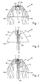
- FIGS. 1 to 5 show an example of a known from the prior art intent optics 10 with exemplified light beam progressions.
- the attachment optics 10 is a semiconductor light source 12, which is preferably designed as a light emitting diode assigned.
- FIG. 1 1 shows a first possible beam path of the light emitted by the semiconductor light source 12 within the optical attachment 10.
- the semiconductor light source 12 is arranged relative to the attachment optics 10 such that as much emitted light of the semiconductor light source 12 radiates in the direction of light coupling surfaces 14 of the attachment optics 10.
- a preferably cylindrical or frustoconical recess 11 is formed on the back of the attachment optics 10, in which the light source 12 is arranged.
- the recess comprises lateral, light coupling surfaces 14a, which extend approximately parallel or at a small angle to an optical axis 20 of the optical attachment 10.
- the Lichteinkoppel vom 14a correspond to a jacket of a recess 11 forming cylinder or a truncated cone.
- the recess 11 preferably has a circular cross-section. Of course, the recess 11 may also have an oval or polygonal cross-section.
- a main emission direction of the light emitted by the light-emitting diode 12 extends substantially parallel to the optical axis 20 of the attachment optics 10.
- a first ray path of the light comprises light beams of the semiconductor light source 12 which are emitted obliquely to the main emission direction and are coupled into the attachment optics 10 at the lateral light coupling surface 14a , The light coupled to the light coupling surfaces 14a then strikes boundary surfaces 16 of the attachment optics 10, where it is reflected by total reflection and deflected in the direction of outcoupling surfaces 18a.
- the light can be bundled, preferably parallelized (collimated). Subsequently, the bundled light at the light output surfaces 18a of the optical attachment 10 is coupled out of this. In this case, the light totally reflected at the boundary surfaces 16 preferably emerges from the attachment optics at decoupling surfaces 18a arranged at a distance from the optical axis 20. Both when entering through the light coupling surfaces 14a and when exiting through the light output surfaces 18a, the light can be refracted, which can be used in addition to the bundling of light. After decoupling from the optical attachment 10, the light beams are substantially parallel.
- FIG. 2 shows a second possible beam path of the emitted light from the semiconductor light source 12 within the attachment optics 10.
- light emitted by the light emitting diode 12 substantially parallel to the main emission direction, via a substantially transverse to the optical axis 20 extending light input surface 14b at the bottom of Well 11 coupled into the optical attachment 10.
- the second beam path of the light runs within the attachment optics 10 substantially along the optical axis 20 of the attachment optics 10.
- the emitted light of the semiconductor light source 12 can meet directly behind the light coupling surface 14 on a lens 22 arranged there, the light, possibly in cooperation with the transverse to the optical axis 20 extending light input surface 14b, bundles, preferably parallelized.
- the lens 22 may also be an integral part of the light input surface 14b. Subsequently, the light strikes a central light output surface 18b, through which the optical axis 20 passes. This too Light is decoupled in a parallel direction at the light outcoupling surface 18b, analogous to the first beam path. In a real operation of the attachment optics 10 both ray trajectories take place simultaneously.
- FIG. 3 shows the interaction of the first and the second beam path in the known optical attachment 10th
- the boundary surfaces 16 and / or the light output surfaces 18 By deforming the light input surfaces 14, the boundary surfaces 16 and / or the light output surfaces 18, the beam path through the optical attachment 10 and thus the light distribution generated can be influenced. So are in FIG. 4 the boundary surface 16 more concave curved than in the FIGS. 1 to 3 shown intent optics 10 and the light output surfaces 18 are also slightly convex curved.
- FIGS. 1 to 4 has been assumed by an ideal point light source.
- the semiconductor light source 12 is an areally extended light source with corresponding surface dimensions.
- FIG. 5 shows such a realistic formed semiconductor light source 12 with the resulting due to the surface extension of the light source 12 beam paths.
- the light distribution is widened and scattered.
- the result of this shape of the surfaces can not produce a sharp gradient of light intensity in the resulting light distribution, for example, to produce a sharp light-dark boundary 42 (see Figures 14 . 20 and 23 ) necessary is.
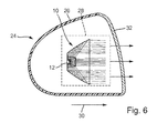
- FIG. 6 shows a headlight according to the invention 24 in a vertical longitudinal section.
- the headlight 24 includes a housing 26 in which a light module 28 for generating a partial light distribution is arranged.
- the light module 28 is preferably used to generate a dimmed partial light distribution with a horizontal light-dark boundary, such as a spotlight distribution or a basic light distribution of a low beam or a fog light.
- the module 28 can also be designed to generate a light distribution with a vertical light-dark boundary, as it is, for example, in a Operafernlicht application.
- An overall light distribution produced by the headlight 24 is preferably obtained by superposing the partial light distribution produced by the module 28 with other partial light distributions generated by other light modules (not shown) arranged in the housing 26.
- the partial light distribution generated by the light module 28 forms the overall light distribution of the headlamp 24 without overlapping with other partial light distributions.
- the headlamp 24 may additionally also comprise any luminaire modules for generating any desired luminaire functions (for example flashing light, daytime running light, parking light, position light).
- the housing 26 of the headlamp 24 has in the light exit direction 30 on a light exit opening, which is closed with a translucent cover 32 to prevent the ingress of dirt and moisture.
- the cover 32 may be formed as a so-called. Clear disc without optically active elements or as a so-called. Lens which is at least partially provided with optically active elements, for example in the form of cylindrical lenses or prisms.
- the light module 28 has the semiconductor light source 12, to which a front attachment 10 according to the invention is assigned.
- the light module 28 may also include a plurality of semiconductor light sources 12 each having an associated attachment optics 10. It is also possible for a plurality of semiconductor light sources 12 to be assigned to a common optical attachment 10.
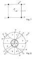
- FIG. 7 shows a plan view of an exemplary luminous surface 13 of the semiconductor light source 12 in a schematic representation.
- the luminous surface 13 has in this embodiment, a quadrangular, substantially square contour, wherein the four vertices of the luminous surface 13 are denoted by the letters A-D.
- Another polygonal contour of the luminous surface 13 is also possible. Even a round or oval contour of the luminous surface 13 would be possible.
- FIG. 8 shows a rear view in the light exit direction 30 as viewed on the attachment optics 10 according to the invention.
- the luminous area 13 of the semiconductor light source 12 is marked with the vertices A to D.
- An essential aspect of the present invention is the subdivision of the boundary surfaces 16 of the optical attachment 10 into a plurality of regions 34, each of which is associated with defined, mutually spaced points of the luminous surface 13. These are preferably arranged along the outer edges of the luminous surface 13. Particularly preferably, the regions 34 are assigned to the corner points A to D of the luminous surface 13 of the semiconductor light source 12. In a round or oval configuration of the luminous surface 13, the points assigned to the regions 34 can be defined as desired, preferably along the outer edges of the luminous surface 13.
- the defined points A to D of the luminous surface 13 are arranged as uniformly as possible spaced apart along the outer edge and each two of the points A to D are arranged diagonally opposite to each other with respect to a center of gravity of the luminous surface 13, respectively.
- the interface 16 is divided into eight regions 34.
- the regions 34 are partly separated by linear boundary lines 36 or by substantially hyperbolic boundary lines 38 due to their construction.
- the boundary surface 16 can be separated along the borderlines 36 and 38.
- Each of the demarcated areas 34 is associated with a specific corner A to D of the luminous area 13 of the semiconductor light source 12.
- the individual areas 34 respectively associated corner A to D of the luminous surface 13 is illustrated by indicating the name of the corner A to D.
- the shape of the boundary line 36; 38 is determined in particular by the condition that only one corner A of a region 34; B; C or D produces the highest point of the image with respect to the Patoscuro boundary.
- the course of the boundary lines 36, 38 is as shown. If the light source 12 has a different shape, a different course of the boundary lines 36, 38 may result.
- the assignment of the points A to D of the luminous surface 13 to the interface regions 34 takes place according to the following principle:
- the regions 34 generate images of the luminous surface 13 of the semiconductor light source 12 on a measuring screen arranged at a distance from the attachment optics 10.
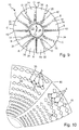
- the images generated by the individual regions 34 are in the FIGS. 9 and 10 drawn by way of example and designated by the reference numeral 35. It will be appreciated that due to the curvature of the regions 34, the images are partially distorted and / or rotated. Due to the curvature you can not turn images.
- the orientation of the images results from the position / shape of the light source 12 and the viewing angle, in which one looks at the light source 12. For each region 34, it holds that when a horizontal light-dark boundary 42 is generated (cf.
- Figures 14 . 20 and 23 the light distribution of the defined point A associated with the area 34; B; C; D of the luminous surface 13 forms the uppermost point of the image 35 generated by the region 34.
- the regions 34 must be formed such that this topmost point of the image 35 is exactly at or as close as possible to the light-dark boundary 42 (cf. Figures 14 and 23 ) lies. This automatically results in that rays from other points or sections of the luminous surface 13 are always below the light-dark boundary 42.
- An area 34 is thus characterized in that a corner point A; B; C or D of the light source 12 is the point which is highest in the light-dark boundary.
- FIG. 9 shows by way of example a plurality of possible images 35 of the luminous surface 13 of the semiconductor light source 12, which are generated by the regions 34 on which the images 35 are drawn.
- the uppermost point is denoted by one of the letters A to D, which is an indication of the corner A to D of the luminous surface 13 which, in the case of the image 35 of the luminous surface 13 generated by the region 34, is the uppermost point of the luminous surface 13 Image 35 forms.
- the attachment optics 10 comprises a plurality of semiconductor light sources 12, for example in the form of a semiconductor light source array (not shown), the points of the luminous area associated with the individual regions 34 of the interface 16 can be defined as the outer corner points of the total luminous area of the entire semiconductor light source array.
- FIG. 10 shows exemplary images 35 in two selected areas 34 of the interface 16 in detail.
- the corner A in FIG. 10 indicated by a circle and the corner B by a filled dot.
- the corner of the image 35 labeled A represents the uppermost corner.
- the corner B identified by way of example and the further corners C and D (not marked) are located in the images generated by the region 34' 35 of the luminous surface 13 always below the corner A or at most at the same height with the corner A.
- the corner B assigned area 34 '' is marked with B corner of the image 35, the top corner, the corner A and the other corners C and D (not marked) are always below the corner B at the images 35 of the luminous surface 13 produced by the region 34 "or at the same height as the corner B.
- FIG. 9 It can also be seen that the regions 34 are delimited or stepped by steps 40 relative to each other.
- the steps 40 may be provided to compensate for a shift of the images 35 generated by the regions 34 due to the distance between the corners A to D of the luminous surface 13.
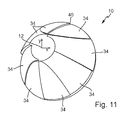
- FIG. 11 shows a perspective rear view of the optical attachment 10, from which also the steps 40 between adjacent areas 34 can be seen.
- 34 steps 40 may be formed between all areas, wherein the height and configuration of the steps 40 may vary almost arbitrarily. It is also conceivable to round off the transitions between the areas 34 so that a continuous rear surface of the attachment optics 10 without kinks, edges and steps is formed.
- the light-dark boundary 42 produced by the optical attachment 10 according to the invention is substantially sharper than the light-dark boundary produced by the known auxiliary optics, while at the same time significantly improving the efficiency of the attachment optics 10.
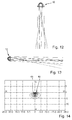
- FIG. 12 shows the attachment optics 10 with the corresponding beam path in a view of the attachment optics 10 in the vertical direction.
- FIG. 13 shows the attachment optics 10 with the corresponding beam path in a view in the horizontal direction from the side of the attachment optics 10.
- a through the beam paths of the FIGS. 12 and 13 generated light distribution on a arranged at a distance from the attachment optics 10 measuring screen shows FIG. 14 ,
- the light distribution has only a small horizontal scattering with an extension of about +/- 5 ° to the right and left of a vertical VV.
- a horizontal light-dark boundary 42 which is approximately at a horizontal HH or just below it, is sharply defined, at least in a range between +/- 3 °.
- the extension of the light bundle in the vertical direction is also relatively small and extends approximately from the horizontal HH downwards by approximately 5 °.
- the light distribution produced in this way represents a spotlight distribution that is in a spotlight module, for example, for improved illumination of the long range of a Low beam distribution, can be used.
- FIGS. 15 to 17 show a further embodiment of the attachment optics 10 of the invention.
- curved surfaces 44 are formed.
- the curved surfaces 44 preferably have a longitudinal extent and are formed, for example, in the form of cylindrical or cylindrical segment-shaped lenses.
- the longitudinal axes of the curved surfaces, in particular the cylinder axes of cylindrical or cylindrical segment-shaped lenses, preferably extend (perpendicularly) transversely to the course of the light-dark boundary 42.
- FIG. 15 shows a plan view in the vertical direction on the attachment optics 10.
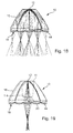
- the decoupled from the outcoupling surface 18 with the curved surfaces 44 light rays are scattered transversely to the extension of the longitudinal axis in the horizontal direction, which is based on the in the FIGS. 18 and 19 illustrated beam trajectories is illustrated.
- the curved surfaces 44 can be arranged either as an integral part of the decoupling surface 18 or as a separate optical element at a distance from the decoupling surface 18 in the beam path of the decoupled light beams.
- FIG. 17 shows a sectional view through the optical attachment 10 from FIG. 15 along the line XVII-XVII with an exemplary drawn beam path. So while the FIGS. 18 and 19 the horizontal scattering of passing through the optical attachment 10 light beams can be seen, shows the FIG. 17 a (hardly existing) vertical scattering of the passing light rays. In the vertical direction, the light passing through the attachment optics 10 is thus bundled relatively strongly. An upper side of the resulting partial light distribution can be used for Generation of the light-dark boundary 42 are used.
- FIG. 17 only shows the so-called second possible beam path according to FIG. 2 which impinges on the decoupling surface 18 via the light-injecting surface 14b through the direct-imaging lens 22 without total internal reflection at the interfaces 16.
- the curved surfaces 44 lead in a corresponding manner also in the first possible beam path according to FIG. 1 in that the light beams coupled into the optical attachment 10 via the lateral coupling-in surfaces 14 strike the decoupling surfaces 18 after a total reflection at the boundary surfaces 16 and are hardly scattered by the curved surfaces in the vertical direction, but rather are bundled.
- boundary surface 16 or the regions 34 with correspondingly configured facets in order to achieve a scattering of the light coupled out of the attachment optics 10.
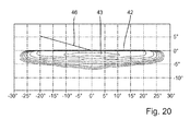
- the optical attachment 10 can be used in a light module 28 of a headlight 24 for generating a light distribution, as exemplified in FIG. 20 is shown.
- This light distribution is well suited for a fog light, a basic light distribution of a low beam headlight or for a turn-off spotlight.
- the light distribution is relatively widely scattered in the horizontal direction (about +/- 28 °) and has a sharp horizontal light-dark boundary 42 on its upper side. Even a region 43 with high light intensity in the center of the light distribution extends in the horizontal direction relatively wide (about +/- 10 °).
- the light distribution causes a wide illumination of the road ahead of the vehicle, especially in the area of the road edges.
- FIG. 20 When the light distribution off FIG. 20 represents a basic light distribution of a low-beam distribution, it can with a spot light distribution (see. FIG. 14 ) are superimposed.
- the spotlight distribution has only a relatively small horizontal extension (about +/- 4 °) and a highly concentrated central region 45 with high light intensity.
- the spotlight distribution when superposed with the basic light distribution, ensures good illumination of a long range of the low beam distribution immediately below the light-dark boundary 42.
- the optical attachment 10 can be rotated together with the light source 12 or the entire light module 28 by 15 ° about the optical axis 20.
- the inclined spotlight distribution which then results on a screen, with its inclined section 42 'of the light-dark boundary is in FIG. 22 shown.
- the from a superposition of the spotlight distribution FIG. 22 and the basic light distribution FIG. 20 resulting low beam distribution is in FIG. 23 represented, wherein in the Figures 22 and 23 shown light distributions are provided for left-hand traffic. In a low beam distribution for legal traffic in the FIG.
- a vertical light-dark boundary (not shown) can be generated, which then also integrates modularly into an overall system for generating a total light distribution, for example a light distribution of a partial high-beam or masked high-beam can be.
- the optical attachment 10 together with the semiconductor light source 12 and the entire light module 28 about axes of rotation which are arranged perpendicular to the optical axis 20, is pivotable.
- the intent optical system 10 according to the invention can also be used for the realization of dynamic lighting functions, since the rotation of the attachment optics 10 and the light module 28 is also possible during a journey.
- a modification of the attachment optics 10 according to the invention, in particular with regard to the configuration of the regions 34 of the interfaces 16, is not necessary for this purpose.
- the drive elements necessary for setting the dynamic light functions can act directly on the attachment optics 10 or the light module 28.
- a dynamic headlamp leveling can be realized, in which an adjustment of the light-dark boundary 42 to a pitch angle of the vehicle, ie to a longitudinal inclination of the vehicle is realized.
- a horizontal pivoting of the attachment optics 10 to a vertical axis to realize a dynamic cornering light, in which when passing through curves, the optical axis 20 is tracked in the direction of the curve.
- the light output surface 18 is not aligned transversely, but substantially parallel to the optical axis 20.
- the coupled into the optical attachment 10 light is reflected at an additional provided, obliquely to the optical axis 20 extending boundary surface 48 in the direction of the decoupling surface 18, preferably totally reflected.
- the further boundary surface 48 can redirect the light coupled into the optical attachment 10, if appropriate after reflection at the boundary surfaces 16, in such a way that a main light exit direction 30 of the light from the attachment optics 10 is at an angle to the optical axis 20, preferably approximately 90 °, is directed.
- the light can be coupled out at any other angles to the optical axis 20 of the attachment optics 10.
- the further boundary surface 48 may be formed such that the light is scattered or bundled after an exit of the light from the light output surface 18. In the in FIG. 24 In the embodiment shown, the further boundary surface 48 is slightly convex, so that the light is scattered slightly out of the light output surface 18. In a more concave formation of the further boundary surface 48, the light would be bundled after emerging from the light output surface 18. Such a configuration of the attachment optics 10 offers the possibility of being able to adapt the attachment optics 10 better to an available installation space.
- the optical attachment 10 it is possible for the optical attachment 10 to have at least one of the regions 34 of the interfaces 16 having steps 50.
- a step-shaped formation of at least one region 34 the distance of the region 34 to the semiconductor light source 12 can be changed, whereby the images of the luminous surface 13 can be increased or decreased.
- steps 50 it is also possible, for example, a zone 43, 45 of the greatest light intensity in the generated light distribution (cf. Figures 20 and 22 ) to move.
- the step-shaped formation may relate to only a single area 34 of the boundary surfaces 16, it may of course also affect several or all areas 34 of the interface 16.
- the invention has been described in such a way that the light-dark boundary is produced by means of the (totally) reflecting boundary surfaces 16.
- the coupling surfaces 14; 14a, 14b and / or the decoupling surfaces 18; 18a, 18b participate in the generation of the light-dark boundary.
- the coupling surfaces 14; 14a, 14b and / or the decoupling surfaces 18; 18a, 18b the light-dark boundary alone, i. generate without the cooperation of the interfaces 16. In this case, all the surfaces 16, 16 cooperating with the generation of the light-dark boundary would then have to be used.
- 14; 14a, 14b; 18; 18a, 18b be divided into areas, wherein an interaction of the area cooperating surfaces 16; 14; 14a, 14b; 18; 18a, 18b, characterized in that by the interaction of the areas of the surfaces a corner A; B; C or D of the light source 12 is the point which is highest in the light-dark boundary.
Landscapes
- Engineering & Computer Science (AREA)
- General Engineering & Computer Science (AREA)
- Physics & Mathematics (AREA)
- Microelectronics & Electronic Packaging (AREA)
- Optics & Photonics (AREA)
- Mathematical Physics (AREA)
- Non-Portable Lighting Devices Or Systems Thereof (AREA)
Applications Claiming Priority (1)
| Application Number | Priority Date | Filing Date | Title |
|---|---|---|---|
| DE201110078653 DE102011078653B4 (de) | 2011-07-05 | 2011-07-05 | Vorsatzoptik zur Bündelung von ausgesandtem Licht mindestens einer Halbleiterlichtquelle |
Publications (2)
| Publication Number | Publication Date |
|---|---|
| EP2543926A2 true EP2543926A2 (fr) | 2013-01-09 |
| EP2543926A3 EP2543926A3 (fr) | 2015-05-20 |
Family
ID=46458291
Family Applications (1)
| Application Number | Title | Priority Date | Filing Date |
|---|---|---|---|
| EP20120174888 Withdrawn EP2543926A3 (fr) | 2011-07-05 | 2012-07-04 | Lentille pour concentrer la lumière envoyée d'au moins une source de lumière semi-conductrice (LED) |
Country Status (2)
| Country | Link |
|---|---|
| EP (1) | EP2543926A3 (fr) |
| DE (1) | DE102011078653B4 (fr) |
Cited By (6)
| Publication number | Priority date | Publication date | Assignee | Title |
|---|---|---|---|---|
| JP2014167879A (ja) * | 2013-02-28 | 2014-09-11 | Koito Mfg Co Ltd | 車両用灯具 |
| EP2818789A3 (fr) * | 2013-04-17 | 2015-08-12 | Stanley Electric Co., Ltd. | Unité d'éclairage pour une lampe de véhicule |
| EP2837566B1 (fr) * | 2013-08-13 | 2019-10-02 | Goodrich Lighting Systems GmbH | Unité extérieure d'éclairage d'aéronef et aéronef comprenant l'unité extérieure d'éclairage d'aéronef |
| WO2020064259A1 (fr) * | 2018-09-28 | 2020-04-02 | Lumileds Holding B.V. | Lentille collimatrice multifocale et ensemble phare à double fonction |
| WO2023025512A1 (fr) * | 2021-08-25 | 2023-03-02 | Bayerische Motoren Werke Aktiengesellschaft | Phare pour un véhicule automobile |
| EP4386256A1 (fr) * | 2022-12-13 | 2024-06-19 | T.Y.C. Brother Industrial Co., Ltd. | Lentille optique pour un vehicule et ensemble lentille optique la comprenant |
Families Citing this family (10)
| Publication number | Priority date | Publication date | Assignee | Title |
|---|---|---|---|---|
| DE102012104845A1 (de) * | 2012-06-05 | 2013-12-19 | Odelo Gmbh | Leuchtdiode mit Lichtleitkörper, insbesondere für eine Nebelschlusslichtfunktion von Fahrzeugleuchten |
| US9156395B2 (en) | 2013-01-08 | 2015-10-13 | Ford Global Technologies, Llc | Low profile highly efficient vehicular LED modules and headlamps |
| US9476557B2 (en) | 2013-01-08 | 2016-10-25 | Ford Global Technologies, Llc | Low profile highly efficient vehicular LED modules and headlamps |
| DE102013202563A1 (de) | 2013-02-18 | 2014-08-21 | Zumtobel Lighting Gmbh | Optik für LED-Lichtquelle |
| DE102013108801B4 (de) * | 2013-08-14 | 2015-10-01 | Sick Ag | Kamera mit einer Beleuchtungsvorrichtung zum Erzeugen eines Beleuchtungsfeldes |
| DE102015119718A1 (de) * | 2014-11-24 | 2016-05-25 | Ford Global Technologies, Llc | Hochwirksame Fahrzeug-LED-Module und Scheinwerfer mit einem niedrigen Profil |
| DE102016118152A1 (de) | 2016-09-26 | 2018-03-29 | Automotive Lighting Reutlingen Gmbh | Lichtmodul für einen Kraftfahrzeugscheinwerfer |
| DE102017220488B4 (de) | 2016-11-24 | 2023-02-16 | Wuhan Tongchang Automotive Lighting Co., Ltd. | Scheinwerfer für Fahrzeuge |
| DE102020111617A1 (de) * | 2020-04-29 | 2021-11-04 | Trilux Gmbh & Co. Kg | Optischer Körper, Lichtmodul und Lichtsystem |
| DE102021124722A1 (de) | 2021-09-24 | 2023-03-30 | Bartenbach Holding Gmbh | Strahler |
Citations (3)
| Publication number | Priority date | Publication date | Assignee | Title |
|---|---|---|---|---|
| DE10310263A1 (de) | 2002-10-24 | 2004-05-13 | Daimlerchrysler Ag | LED-Scheinwerfer zur asymmetrischen Ausleuchtung |
| DE10312364A1 (de) | 2003-03-20 | 2005-01-27 | Daimlerchrysler Ag | Scheinwerfer zur Erzeugung einer deutlichen Hell-Dunkel-Grenze auf der Fahrbahn |
| DE102008061619A1 (de) | 2007-12-12 | 2009-06-25 | Koito Manufacturing Co., Ltd. | Fahrzeugleuchte |
Family Cites Families (9)
| Publication number | Priority date | Publication date | Assignee | Title |
|---|---|---|---|---|
| ATE383544T1 (de) * | 2004-05-14 | 2008-01-15 | Fiat Ricerche | Einheit zur projektion eines lichtbündels, eine optische vorrichtung für die einheit, und fahrzeug frontlichteinrichtung |
| US8631787B2 (en) * | 2005-07-28 | 2014-01-21 | Light Prescriptions Innovators, Llc | Multi-junction solar cells with a homogenizer system and coupled non-imaging light concentrator |
| US7837349B2 (en) * | 2007-06-15 | 2010-11-23 | Visteon Global Technologies, Inc. | Near field lens |
| DE102008013603B4 (de) * | 2008-03-11 | 2017-06-22 | Automotive Lighting Reutlingen Gmbh | Lichtmodul für eine Beleuchtungseinrichtung |
| JP5070129B2 (ja) * | 2008-05-22 | 2012-11-07 | 株式会社小糸製作所 | 車両用照明灯具 |
| JP5179328B2 (ja) * | 2008-11-20 | 2013-04-10 | 株式会社小糸製作所 | 車両用照明灯具 |
| JP5369359B2 (ja) * | 2009-04-13 | 2013-12-18 | スタンレー電気株式会社 | 灯具 |
| DE102009035544B4 (de) * | 2009-07-31 | 2019-10-24 | Volkswagen Ag | Scheinwerfer in einem Kraftfahrzeug mit mehreren Halbleiterlichtquellen |
| JP5475395B2 (ja) * | 2009-10-23 | 2014-04-16 | スタンレー電気株式会社 | 車両用灯具 |
-
2011
- 2011-07-05 DE DE201110078653 patent/DE102011078653B4/de active Active
-
2012
- 2012-07-04 EP EP20120174888 patent/EP2543926A3/fr not_active Withdrawn
Patent Citations (3)
| Publication number | Priority date | Publication date | Assignee | Title |
|---|---|---|---|---|
| DE10310263A1 (de) | 2002-10-24 | 2004-05-13 | Daimlerchrysler Ag | LED-Scheinwerfer zur asymmetrischen Ausleuchtung |
| DE10312364A1 (de) | 2003-03-20 | 2005-01-27 | Daimlerchrysler Ag | Scheinwerfer zur Erzeugung einer deutlichen Hell-Dunkel-Grenze auf der Fahrbahn |
| DE102008061619A1 (de) | 2007-12-12 | 2009-06-25 | Koito Manufacturing Co., Ltd. | Fahrzeugleuchte |
Cited By (9)
| Publication number | Priority date | Publication date | Assignee | Title |
|---|---|---|---|---|
| JP2014167879A (ja) * | 2013-02-28 | 2014-09-11 | Koito Mfg Co Ltd | 車両用灯具 |
| EP2818789A3 (fr) * | 2013-04-17 | 2015-08-12 | Stanley Electric Co., Ltd. | Unité d'éclairage pour une lampe de véhicule |
| EP2837566B1 (fr) * | 2013-08-13 | 2019-10-02 | Goodrich Lighting Systems GmbH | Unité extérieure d'éclairage d'aéronef et aéronef comprenant l'unité extérieure d'éclairage d'aéronef |
| WO2020064259A1 (fr) * | 2018-09-28 | 2020-04-02 | Lumileds Holding B.V. | Lentille collimatrice multifocale et ensemble phare à double fonction |
| US10890307B2 (en) | 2018-09-28 | 2021-01-12 | Lumileds Llc | Multi-focal collimating lens and bi-function headlight assembly |
| CN113242948A (zh) * | 2018-09-28 | 2021-08-10 | 亮锐有限责任公司 | 多焦点准直透镜和双功能前照灯组件 |
| CN113242948B (zh) * | 2018-09-28 | 2022-05-03 | 亮锐有限责任公司 | 多焦点准直透镜和双功能前照灯组件 |
| WO2023025512A1 (fr) * | 2021-08-25 | 2023-03-02 | Bayerische Motoren Werke Aktiengesellschaft | Phare pour un véhicule automobile |
| EP4386256A1 (fr) * | 2022-12-13 | 2024-06-19 | T.Y.C. Brother Industrial Co., Ltd. | Lentille optique pour un vehicule et ensemble lentille optique la comprenant |
Also Published As
| Publication number | Publication date |
|---|---|
| DE102011078653B4 (de) | 2013-12-12 |
| DE102011078653A1 (de) | 2013-01-10 |
| EP2543926A3 (fr) | 2015-05-20 |
Similar Documents
| Publication | Publication Date | Title |
|---|---|---|
| DE102011078653B4 (de) | Vorsatzoptik zur Bündelung von ausgesandtem Licht mindestens einer Halbleiterlichtquelle | |
| EP3343091B1 (fr) | Module d'éclairage de phare de véhicule automobile | |
| EP3351849B1 (fr) | Module à led et dispositif d'éclairage pour un véhicule automobile pourvu d'une pluralité de tels modules à led | |
| DE10009782B4 (de) | Beleuchtungseinrichtung eines Fahrzeugs | |
| DE102009008631B4 (de) | Projektionsmodul für einen Kraftfahrzeugscheinwerfer | |
| EP2799761B1 (fr) | Module d'éclairage de phare de véhicule automobile | |
| DE102005015007B4 (de) | Fahrzeugleuchte | |
| DE102009053581B3 (de) | Lichtmodul für eine Beleuchtungseinrichtung eines Kraftfahrzeugs | |
| EP2742280B1 (fr) | Module de sources lumineuses à del pour un projecteur de véhicule | |
| EP2523022B1 (fr) | Module d'éclairage pour un phare de véhicule automobile destiné à la production d'une distribution lumineuse variable et phare de véhicule automobile doté d'un tel module d'éclairage | |
| EP2492580B1 (fr) | Dispositif d'éclairage prévu pour l'intégration dans un véhicule automobile | |
| DE102009010558B4 (de) | Lichtmodul für einen Scheinwerfer eines Kraftfahrzeugs und Kraftfahrzeugscheinwerfer mit einem solchen Lichtmodul | |
| DE60302708T2 (de) | Kfz-Scheinwerfer nach dem Projektionsprinzip mit einer sekundären Lichtquelle | |
| DE102014205994B4 (de) | Lichtmodul mit Halbleiterlichtquelle und Vorsatzoptik und Kraftfahrzeugscheinwerfer mit einem solchen Lichtmodul | |
| DE102009022848B4 (de) | Scheinwerferanordnung und Scheinwerfersystem für ein Kraftfahrzeug | |
| DE102011077636A1 (de) | Lichtmodul eines Kraftfahrzeugs zur Erzeugung einer Spotverteilung einer Fernlicht-Lichtverteilung und Kraftfahrzeugscheinwerfer mit einem solchen Modul | |
| DE102009037698A1 (de) | Fahrzeugbeleuchtungseinheit und Fahrzeugleuchte | |
| DE102006037422A1 (de) | Fahrzeugleuchte | |
| EP1864053A1 (fr) | Phare de vehicule | |
| DE202010006097U1 (de) | Lichtmodul für einen Kraftfahrzeugscheinwerfer | |
| DE102009035743A1 (de) | Lichtmodul für einen Kraftfahrzeugscheinwerfer | |
| WO2011154470A1 (fr) | Accessoire optique constitué d'un matériau transparent pour la focalisation de lumière, ensemble de lentilles comportant au moins un tel accessoire optique, et module de lumière doté d'un tel ensemble de lentilles | |
| DE102013220192B4 (de) | LED-Modul eines Kraftfahrzeugscheinwerfers | |
| EP3301350B1 (fr) | Module d'éclairage pour phare de véhicule automobile | |
| WO2014165884A2 (fr) | Unité lumineuse dotée d'un cache pourvu d'au moins une fenêtre optique |
Legal Events
| Date | Code | Title | Description |
|---|---|---|---|
| PUAI | Public reference made under article 153(3) epc to a published international application that has entered the european phase |
Free format text: ORIGINAL CODE: 0009012 |
|
| AK | Designated contracting states |
Kind code of ref document: A2 Designated state(s): AL AT BE BG CH CY CZ DE DK EE ES FI FR GB GR HR HU IE IS IT LI LT LU LV MC MK MT NL NO PL PT RO RS SE SI SK SM TR |
|
| AX | Request for extension of the european patent |
Extension state: BA ME |
|
| PUAL | Search report despatched |
Free format text: ORIGINAL CODE: 0009013 |
|
| AK | Designated contracting states |
Kind code of ref document: A3 Designated state(s): AL AT BE BG CH CY CZ DE DK EE ES FI FR GB GR HR HU IE IS IT LI LT LU LV MC MK MT NL NO PL PT RO RS SE SI SK SM TR |
|
| AX | Request for extension of the european patent |
Extension state: BA ME |
|
| RIC1 | Information provided on ipc code assigned before grant |
Ipc: F21S 8/12 20060101AFI20150410BHEP Ipc: F21V 5/00 20150101ALI20150410BHEP Ipc: F21V 7/00 20060101ALI20150410BHEP Ipc: F21S 8/10 20060101ALI20150410BHEP |
|
| STAA | Information on the status of an ep patent application or granted ep patent |
Free format text: STATUS: THE APPLICATION IS DEEMED TO BE WITHDRAWN |
|
| 18D | Application deemed to be withdrawn |
Effective date: 20151121 |