EP2543977A1 - Procédé et appareil pour diagnostiquer l'état d'un coussinet - Google Patents
Procédé et appareil pour diagnostiquer l'état d'un coussinet Download PDFInfo
- Publication number
- EP2543977A1 EP2543977A1 EP11750503A EP11750503A EP2543977A1 EP 2543977 A1 EP2543977 A1 EP 2543977A1 EP 11750503 A EP11750503 A EP 11750503A EP 11750503 A EP11750503 A EP 11750503A EP 2543977 A1 EP2543977 A1 EP 2543977A1
- Authority
- EP
- European Patent Office
- Prior art keywords
- slide bearing
- acceleration
- value
- correlation
- spectrum
- Prior art date
- Legal status (The legal status is an assumption and is not a legal conclusion. Google has not performed a legal analysis and makes no representation as to the accuracy of the status listed.)
- Granted
Links
Images









Classifications
-
- G—PHYSICS
- G01—MEASURING; TESTING
- G01H—MEASUREMENT OF MECHANICAL VIBRATIONS OR ULTRASONIC, SONIC OR INFRASONIC WAVES
- G01H17/00—Measuring mechanical vibrations or ultrasonic, sonic or infrasonic waves, not provided for in the other groups of this subclass
-
- G—PHYSICS
- G01—MEASURING; TESTING
- G01M—TESTING STATIC OR DYNAMIC BALANCE OF MACHINES OR STRUCTURES; TESTING OF STRUCTURES OR APPARATUS, NOT OTHERWISE PROVIDED FOR
- G01M13/00—Testing of machine parts
- G01M13/04—Bearings
- G01M13/045—Acoustic or vibration analysis
-
- G—PHYSICS
- G01—MEASURING; TESTING
- G01H—MEASUREMENT OF MECHANICAL VIBRATIONS OR ULTRASONIC, SONIC OR INFRASONIC WAVES
- G01H1/00—Measuring characteristics of vibrations in solids by using direct conduction to the detector
-
- G—PHYSICS
- G01—MEASURING; TESTING
- G01H—MEASUREMENT OF MECHANICAL VIBRATIONS OR ULTRASONIC, SONIC OR INFRASONIC WAVES
- G01H1/00—Measuring characteristics of vibrations in solids by using direct conduction to the detector
- G01H1/12—Measuring characteristics of vibrations in solids by using direct conduction to the detector of longitudinal or not specified vibrations
- G01H1/14—Frequency
-
- G—PHYSICS
- G01—MEASURING; TESTING
- G01H—MEASUREMENT OF MECHANICAL VIBRATIONS OR ULTRASONIC, SONIC OR INFRASONIC WAVES
- G01H5/00—Measuring propagation velocity of ultrasonic, sonic or infrasonic waves, e.g. of pressure waves
Definitions
- the present invention relates to a diagnostic method and a diagnostic device for a slide bearing. More particularly, the present invention relates to an improvement of a diagnostic analysis method for detecting a sign of a bearing contact (rubbing) specific to a slide bearing of a ship or a power generation facility.
- the slide bearing is also used as a bearing of a diesel engine for a ship or a power generation facility.
- the slide bearing in general, is not subjected to damage since it is surrounded by an oil film and rotates in a contactless manner.
- an execution failure or a blade unbalance can cause a coupling misalignment, and a rotating shaft can contact (rub) the slide bearing due to an abnormal vibration caused by an oil whip, thereby causing damage.
- a vibration or sound occurs that is different from usual. If an actuation is continued in such a state, damage may be caused.
- a burn may occur, thereby resulting in a stop in the equipment.
- a method using a shaft vibration due to an eddy current type sensor or a bearing housing vibration due to a piezoelectric acceleration sensor is suggested.
- a spectral pattern obtained by applying a fast Fourier transform (FFT) to waveform data such as vibrations or sound which occur from the slide bearing is compared to a preset spectral pattern in an emergency condition, the slide bearing could be diagnosed based on the compared result.
- FFT fast Fourier transform
- the following method comprising: for example, detecting the sound which occurs when the rotating shaft contacts the bearing; retrieving the acoustic signal; subjecting the acoustic signal to an envelope detection process (envelope process); forming data after the envelope detection; comparing a cepstrum value with a reference value; and, based on this determination result, performing a rubbing determination (see patent document 1). If the occurrence of the rubbing phenomenon which is an initial stage of a burn damage of the slide bearing can be detected early, at a minor stage, the burn damage may be obviated.
- Patent Document 1 JP8-261817 A
- the object of the present invention is to provide a diagnostic method and a diagnostic device which is capable of accurately detecting the sign of a minor rubbing abnormality of a slide bearing.
- the present inventors have made various considerations to achieve the accurate detection of the abnormalities specific to slide bearings only with an acceleration sensor and an application to slide bearings which involves a vibration noise associated with a piston movement and a burst or supply/exhaust, as in a diesel engine.
- the acceleration spectrum the spectrum in which the acceleration waveform has been changed to the frequency domain (hereinafter, referred to as the acceleration spectrum) is subjected to a frequency modulation in addition to the amplitude modulation even though the increase in the acceleration level is small.
- the frequency modulation is configured of a plurality of peaks at a rotational frequency interval of a shaft to be detected (hereinafter, simply referred to as the shaft). Furthermore, the present inventors have conceived of quantitatively capturing minor rubbings by subjecting peak information which occurs at a rotational frequency interval of the shaft of the acceleration spectrum to a predetermined signal process using rotational frequency information of the shaft, and thus gaining new knowledge leading to the solving of the problem.
- the present inventors have performed an experiment which forcibly generates a rubbing in the slide bearing and found out that the frequency modulation is clearly generated in a minor rubbing stage. Furthermore, it has been found out that an abnormality detection from the minor rubbing stage would be possible by retrieving the frequency modulation component by a cepstrum analysis. Since the quefrency of a rotational period occurs when a rubbing is generated, a rotational period is automatically calculated from the revolution speed obtained from a revolution indicator to monitor a peak value of the quefrency corresponding to the rotational period. If this peak value exceeds the predetermined threshold value, the occurrence of the rubbing may be informed such as by an alarm device.
- the present invention is based on this finding and is as follows. Namely, the present invention performs the following: detecting waveform data which represents an acceleration of a vibration which occurs when a slide bearing is in operation; transforming acceleration waveform data into an acceleration spectrum of a frequency domain by applying a Fourier transform to the acceleration waveform data; quantifying a plurality of peak information which occurs at a rotational frequency interval of a shaft to be measured in the acceleration spectrum by performing a predetermined signal process combined with rotational frequency information of the shaft; obtaining a characteristic value; monitoring whether the obtained characteristic value has exceeded a predetermined threshold value; and when the characteristic value has exceeded the threshold value, determining that an abnormality has occurred in the slide bearing.
- the sensitivity is higher than that of the conventional detection method which has focused only on amplitude modulation. Even when a vibration noise associated with a piston movement and a burst or supply/exhaust, as in the slide bearing of a diesel engine, are involved, the rubbing phenomenon can be detected in a highly-sensitive manner by detecting the frequency modulation (a plurality of peak information at a rotational frequency interval of a shaft) which is associated with a rubbing.
- a frequency analysis be performed after subjecting a burst type waveform of an acoustic signal, which occurs due to contact of the shaft, to an envelope detection process.
- this method does not detect the frequency modulation but instead diagnoses the slide bearing based only on the amplitude modulation component of the data, and thus it is a method with a different principle than that of the present invention.
- an abnormality such as a backlash, which only occurs with the amplitude modulation component in the slide bearing, occurs, in a frequency analysis after the enveloping, the rotational frequency and the high-order component thereof similar to that during the rubbing occur due to a backlash.
- the present invention which directly analyzes the frequency of the vibration signal and processes the frequency modulation which occurs at a revolution speed interval of the shaft occurring thereat, since there would be no frequency modulation even if a backlash were to occur, the determination of the rubbing abnormality would be possible.
- a diagnostic method it is preferable to perform a cepstrum calculation which applies an inverse Fourier transform after a logarithmic transformation is applied to an acceleration spectrum, obtain time-series data of a quefrency value which is obtained from waveform data after the cepstrum calculation, monitor whether or not the quefrency value has exceeded the predetermined threshold value, and when the quefrency value has exceeded the threshold value, determine that an abnormality has occurred in the slide bearing.
- the cepstrum calculation has a lower frequency dependency of an acceleration spectrum used in a calculation. Therefore, usually, the cesptrum calculation can be applied to the diagnostic technique by calculating within an effective frequency domain determined from the sampling interval of data collection and the sensitivity of the sensor.
- a diagnostic method which is different from the cepstrum calculation
- a diagnostic method that is different from the above two examples, it is preferable to perform a calculation which determines a cross-correlation between the acceleration spectrum and the predetermined spectrum, monitor whether or not the cross-correlation value obtained by the calculation has exceeded the predetermined threshold value and when the cross-correlation value has exceeded the threshold value, determine that an abnormality has occurred in the slide bearing.
- the abnormality When an abnormality has occurred in the slide bearing, unless the acceleration of the vibration which occurs due to the abnormality is significantly large, usually, the abnormality is merely such that the rotating shaft slightly contacts the inner periphery of the bearing, and thus the change in the acceleration waveform data is small. Therefore, it is extremely difficult to detect the abnormality only from the waveform data. However, even if there is a slight contact, in an acceleration spectrum of a frequency domain in which the acceleration waveform data has been Fourier-transformed, the present inventors have found out that the frequency modulation, that is, the plurality of peaks which occurs at a rotational frequency interval of the shaft, will occur.
- the frequency modulation occurs at a rotational frequency interval of the shaft, it is possible to obtain a characteristic value which involves a frequency modulation by performing a predetermined signal process in which the rotational frequency information of the shaft and the acceleration spectrum of the frequency domain are combined.
- the characteristic value is monitored and it exceeds the predetermined threshold value, it can be determined that the slide bearing to be measured is abnormal.
- Various methods may be considered as a method for obtaining the characteristic value and a method for diagnosing an abnormality. For example, when the acceleration spectrum of the frequency domain is converted to a logarithm and an analysis in which this logarithm spectrum is inverse Fourier transformed, i.e. a cepstrum analysis is performed, a cepstrum in which a quefrency of a part corresponding to a rotational period in the slide bearing appears can be obtained.
- the horizontal axis of the cepstrum has a time dimension since the function on the frequency axis is Fourier-transformed.
- time series data on a level of a quefrency value (defined as a quefrency level) which corresponds to a shaft rotational period of a slide bearing part to be diagnosed is obtained, the quefrency level is monitored as to whether or not it has exceeded the predetermined threshold value, and when the quefrency value has exceeded the threshold value during the monitoring, it can be determined that an abnormality has occurred in the slide bearing in accordance with the rotational frequency fr of the slide bearing.
- a cepstrum analysis is an analytical method which applies an inverse Fourier transform after the amplitude of the spectrum which has been obtained by applying a Fourier transform to the acceleration waveform detected by a piezoelectric acceleration sensor has been subjected to a logarithmic transformation, and it finds the regularity of the generation frequency component of the spectrum. If the spectrum has regularity, a peak of a period referred to as the quefrency will occur.
- the characteristic value in addition to the cepstrum analysis or the auto-correlation analysis, it is possible to obtain the characteristic value even in a cross-correlation analysis. Namely, it is possible to obtain the characteristic value by a cross-correlation of the acceleration spectrum X and an artificial spectrum (referred to as the template waveform) Y which has a predetermined peak of a rectangular or Gaussian distribution at a rotational period interval of a shaft.
- the data length of the template waveform Y can be configured from a waveform that is the same as the acceleration spectrum X or shorter. With the length of the Y waveform being M, when the length of M is shorter than that of length N' of the acceleration spectrum X, 0 is added such that the length is the same as that of X and then calculated in formula 2.
- a predetermined artificial spectrum having a peak for each rotational frequency of a shaft is prepared in advance as a spectrum of a frequency domain of a vibration acceleration, a cross-correlation between the artificial spectrum and the acceleration spectrum is calculated, and the characteristic value is calculated in a predetermined frequency domain comprising the highest frequency domain of the cross-correlation.
- the present inventors have found out that it is preferable to limit the frequency domain for calculating the characteristic value in a spectrum of the frequency domain which calculates the above auto-correlation or the cross-correlation. Namely, the present inventors have found out that there exist cases where there is a frequency domain in which a plurality of peaks at a rotational frequency interval of the shaft involved in the occurrence of the rubbing is remarkable and cases where there is a frequency domain in which a peak not at a rotational frequency interval is remarkable. Therefore, it is preferable to limit the frequency domain for obtaining the characteristic value.
- Preferable frequencies mean that the characteristic value is calculated in a predetermined frequency domain from 1,000 [Hz] to 20,000 [Hz].
- the method of determining a predetermined frequency is capable of determining the frequency at the periphery where the peak has occurred in, for example, the frequency spectrum. Moreover, a template having a peak for every rotational frequency of the shaft described above is prepared, a value in which an average of the template length is added to m in formula 2 where the cross-correlation Rxy is at a maximum is calculated, and the frequency corresponding to the calculated value is determined. The frequency thus determined is the one which would have the maximum correlation with the template and such frequency can be determined within a predetermined range comprising said frequency.
- the periphery of the maximum peak in the spectrum of the frequency domain from 1,000 [Hz] to 20,000 [Hz] may alternatively be used, but the above method can obtain more preferable results.
- a minor rubbing can be found quantitatively by using peak information of a plurality of acceleration spectra which is frequency-modulated at a rotational frequency of the shaft as described above.
- an abnormality can be detected early and accurately by only using an acceleration sensor and without the need to use an AE (Acoustic Emission) sensor.
- AE Acoustic Emission
- this can also be applied to a diagnosis in a case where a vibration noise associated with a piston movement and a burst or supply/exhaust, such as in the slide bearing of a diesel engine, is involved.
- an abnormal state of the rubbing which conventionally could not be detected by only an acceleration sensor can be detected accurately and at an early point. Therefore, for example, if a minor rubbing state can be detected at a diagnosis after a periodical inspection during a trial operation of the slide bearing, an execution failure can be corrected, and a trouble resulting in a burn can be obviated.
- Detecting a rubbing abnormality in the slide bearing at an early point contributes to the stabilization of or the extension of the periodical inspection period for the operation of an appliance or piece of equipment (for example, large-sized critical rotating equipment or rapid rotating equipment such as compressors) comprising the slide bearing, and further to the determination of the remaining life thereof.
- the present invention is suitable for being applied to a diesel engine which did not previously have a method of being able to directly diagnose bearing abnormalities.
- a diesel engine in general, is configured of a plurality of cylinders and includes the same number of bearings. Therefore, it is difficult to balance all of the bearings due to distortion and the like of the shaft, and thus it is easy for rubbing to occur.
- the bearing may be mounted inside a movable body in a marine engine, it is placed under an even more severe environment. The damage caused due to a breakage while out at sea is significant. According to the present invention, an abnormality of the slide bearing in such diesel engines can be detected, the handling of the component exchange can be performed systematically before fatal damage occurs, and this could largely contribute to safe operations and a reduction in the risk of accidents.
- a sign of a minor rubbing abnormality of a slide bearing can be accurately detected.
- Figs. 1-6 show an embodiment of a diagnostic method and a diagnostic device for a slide bearing according to the present invention.
- Slide bearing 1 is a bearing device of a rotating shaft 2 which is applicable to large-sized critical rotating equipment such as a turbine and rapid rotating equipment such as a compressor.
- a diagnostic device 10 of the slide bearing 1 according to the present invention comprises a revolution speed detection sensor 11, an acceleration sensor 12, a monitoring device 13 and a reporting device 14.
- a configuration of the diagnostic device 10 will be first described below (see Figs. 1 , 2 , etc.).
- the revolution speed detection sensor 11 is a sensor for detecting the revolution speed of the rotating shaft 2.
- the revolution speed detection sensor 11 is configured of a member to be detected 11b that is provided on a surface of the rotating shaft 2 and is made, for example, of a reflective tape which rotates together with the rotating shaft 2, and a pulse detector 11a which detects the rotational pulse of the rotating shaft 2 through the member to be detected 11b (see Fig. 1 ).
- the data detected by the pulse detector 11a is transmitted to the monitoring device 13.
- the revolution speed of the rotating shaft 2 in a real machine is controlled.
- the pulse can be used to accurately detect the revolution speed even in the case where the revolution speed of the rotating shaft 2 varies from moment to moment.
- the acceleration sensor 12 is a sensor for detecting the acceleration during vibration of the rotating shaft 2 based on the vibration at the time when a rubbing phenomenon occurs.
- a piezoelectric acceleration sensor having a piezo element is used to mount the acceleration sensor 12 to a bearing housing of the slide bearing 1 and detects the acceleration based on the vibration of the bearing housing (see Fig. 1 ).
- the detection data of this acceleration sensor 12 is transmitted to the monitoring device 13.
- the monitoring device 13 is a device which performs a diagnosis of the slide bearing 1 based on the transmission data from the above revolution speed detection sensor 11 and the transmission data from the acceleration sensor 12, and transmits the result to a reporting device 14 when it is determined that an abnormality has occurred.
- the monitoring device 13 of the present embodiment transforms the waveform data representing the acceleration of the vibration detected by the acceleration sensor 12 to a power spectrum of a frequency domain by applying a Fourier transform thereto; quantifies a plurality of peak information occurring at a rotational frequency interval of a shaft in the spectrum by performing a predetermined signal process combined with rotational frequency information of the shaft; obtains a characteristic value; monitors whether the obtained characteristic value has exceeded a predetermined threshold value; and when the characteristic value has exceeded the threshold value, determines that an abnormality has occurred in the slide bearing 1.
- the monitoring device 13 of the present embodiment is connected to an arithmetic processing unit (for example, a personal computer).
- the reporting device 14 is a device for outputting the diagnosis result when the monitoring device 13 determines that an abnormality has occurred in the slide bearing 1 and reporting the same to the user and the involved parties.
- the reporting device 14 may report to the outside, for example, by flashing a light or ringing an alarm sound, or may report to the involved parties by using a screen of the arithmetic processing unit 15.
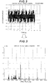
- the acceleration waveform data in which the time is the horizontal axis can be detected (see Fig. 2 ). If an abnormality has occurred in the slide bearing 1, unless the acceleration of the vibration which occurs due to the abnormality is significantly large, the change in acceleration amplitude in the acceleration waveform data, for example, when a minor rubbing has occurred, will be small, and it is extremely difficult to detect the existence of the abnormality only from this waveform data.
- the acceleration waveform data is subjected to a Fourier transform to analyze the frequency, and the waveform data of the frequency domain is obtained (see Fig. 3 ). This causes a power spectrum with the frequency being the horizontal axis to be obtained.
- the plurality of peak information which occurs at a rotational frequency interval of the shaft at the spectrum is quantified by performing a predetermined signal process combined with the rotational frequency information of the shaft to obtain a characteristic value.
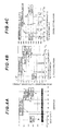
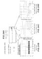
- the logarithm spectrum of the spectrum of the frequency domain is calculated, the logarithm spectrum is subjected to an inverse Fourier transform (cepstrum calculation), and a quefrency value obtained from the waveform data after the cepstrum calculation is used (see Fig. 4A ). Since the quefrency has a peak at a position of a multiple of a rotational period of the shaft, the plurality of peaks may be added to obtain a characteristic value.
- an auto-correlation value of the acceleration spectrum as described below (see Fig. 4B ). Namely, when N-number (524288 in the present embodiment) of acceleration data is collected at a sampling frequency Z[Hz] (51,200 [Hz]) in the present embodiment), the acceleration spectrum of the frequency domain can be decomposed into N-number of frequency domains from Z/N [Hz] to Z [Hz]. However, a commonly effective frequency domain is less than half of Z [Hz].
- the spectrum is shown here with an X as a data column (vector) until length N'. With respect to this X, an auto-correlation as in the above formula 1 is calculated, with m being from 0 to N'-1.
- a large peak value will appear when the m of Rxx(m) (in a frequency conversion, m * Z/N [Hz]) is a value which corresponds to a multiple of the rotational period.
- a peak having other than a multiple of zero, for example, the first peak value, may be the characteristic value.
- the frequency domain of the acceleration spectrum in this process is limited from 1,000 [Hz] to 20,000 [Hz] of the effective frequency as described below.
- a rectangular wave with a peak at a rotational frequency interval is prepared (see Fig. 5 ).
- a rectangular wave with 10 peaks where the length of the peak width is 1/10 th of the rotational period is prepared so as to determine a value of m in which the value of the cross-correlation of formula 2 of this rectangular wave and the acceleration spectrum is at a maximum.
- the average data length w of the rectangular wave is determined.
- the value R [Hz] of the frequency (m+w) x Z/N [Hz] is the center frequency of the acceleration spectrum which has the highest correlation with the rectangular wave.
- the range of ⁇ 1,000 [Hz] of the value R [Hz] is designated.
- the range of 1,000 [Hz] to 3,000 [Hz] is designated. If the value exceeds the upper limit of the effective range (20,000 [Hz] in the present example), the range is 18,000 [Hz] to 20,000 [Hz].
- the rectangular wave used for determining the frequency instead of the rectangular wave used for determining the frequency, other waveforms such as a Gaussian distribution can also be used.
- the peak width or length is not limited to the above.
- the users can determine the range from the acceleration spectrum.
- the peak value of the auto-correlation which is the characteristic value described above may be affected by the base line (see Fig. 4B ), and it is desirable to subtract the base line amount or to divide the peak value by the average value of the base line.
- the average value is subtracted.
- the auto-correlation has a peak at a position of a multiple of a rotational period of the shaft, a plurality of peaks may be added to obtain the characteristic value.
- the characteristic value can be obtained by a cross-correlation of an artificial spectrum (referred to as a template waveform) Y, which has a predetermined peak such as a rectangular or Gaussian distribution at a rotational period interval of a shaft, and the acceleration spectrum X described above.
- the data length of the template waveform Y may be the same as the acceleration spectrum X or may be configured of a shorter waveform.
- the correction of the peak by the base line and the frequency of the acceleration spectrum which calculates the cross-correlation both employ the same method as in the case of the auto-correlation.
- the template which determines the cross-correlation has a width of 1/10 th of the rotational frequency of the shaft, and for the range specified by the acceleration spectrum, the range that is shorter for 2.5 periods of the rotational frequency of the shaft has been used.
- the template has peaks at a rotational frequency interval of the shaft, it is not limited to a rectangular wave. Moreover, the width and the length of the peak are not limited to those of the present embodiment. Since the cross-correlation has peaks at positions for multiples of the rotational period of the shaft, a plurality of peaks may be added to obtain the characteristic value.
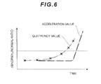
- a predetermined threshold value is set in advance to this characteristic value, and it is determined that an abnormality has occurred in the slide bearing 1 at the time when the temporally-changed characteristic value L has exceeded the threshold value.
- a determination that an abnormality (contact) has occurred in the slide bearing 1 is made when the average value of +3 ⁇ (standard deviation) in a normal state of the quefrency trend level has been exceeded, and this value is the predetermined threshold value.
- the way of thinking regarding the threshold value as described above is the same in the case of using the auto-correlation value of the acceleration spectrum as the characteristic value (see Fig. 4B ) and in the case of using a cross-correlation of the acceleration spectrum as the characteristic value (see Fig. 4C ).
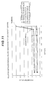
- the threshold value will be further explained based on the specific example shown in Fig. 27 .
- the average value of the quefrency trend level determined by the calculation from the actual data is 0.0343 and the standard deviation ⁇ is 0.0071.
- the average value of +3 ⁇ is 0.00556 (see the broken line which represents the threshold value in Fig. 27 ).
- the threshold value may be a value that is slightly larger than the average value of +3 ⁇ , there is no practical issue.
- the periodicity buried in the spectrum can be detected and the fundamental frequency (or the inverse of the fundamental frequency) can be determined. Based on this, an accurate detection is possible even in the case of a minor rubbing, and the signs thereof can be found at an early stage. Furthermore, in the present embodiment, a diagnosis of the abnormality which directly uses the conventionally-used acceleration sensor is possible.
- the slide bearing 1 according to the present invention is applicable to large-sized critical rotating equipment and rapid rotating equipment, such as a compressor.
- the applicable field or range in this case may include the slide bearing of the rotating appliance in, for example, a petrochemical plant, a nuclear power plant, an oil refinery or a steel plant.
- it may also be applicable to a bearing with a vibration or acoustic noise caused by a piston movement or a burst in a marine diesel engine or a diesel generator, which has been previously difficult to be detected.
- a vibration that receives a frequency modulation once in two rotations due to a burst occurs in a diesel engine even in a normal state.
- the vibration waveform is subjected to a frequency modulation with a periodicity of the rotational frequency due to the strength of the contact pressure by an eccentricity of the main shaft.
- a side band of the rotational period occurs in the vibration acceleration spectrum. That is, the signal by the burst and the signal by the rubbing can be separated depending on the occurrence period of the quefrency.
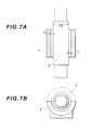
- the rotating shaft 2 was rotated at several speeds (see Figs. 7A and 7B ).
- the peripheries of both ends of the rotating shaft 2 were supported by a support bearing (rolling bearing) and a motor was used to rotate the rotating shaft 2.
- the slide bearing 1 was horizontally moved in a direction perpendicular to the central axis of the rotating shaft 2 by a movement mechanism using a machine bolt (a mechanism which places and pushes the tip of the bolt against the target to be moved so as to move the target) to change the gap B.
- a machine bolt a mechanism which places and pushes the tip of the bolt against the target to be moved so as to move the target
- an experiment was performed with the rotational speeds of 1200 [rpm], 1800 [rpm] and 2800 [rpm] of the rotating shaft 2.
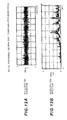
- the present inventors have considered the acceleration waveform and each waveform of the acceleration spectrum when the revolution speed is 1200 [rpm] and the gap is 1/100 [mm] (minor rubbing state) (see Figs. 12A and 12B ). From this result, in the case of a minor rubbing, it has been found that the rising level of the acceleration spectrum was small.
- the present inventors have also considered the waveform of the zooming spectrum when the revolution speed is 1200 [rpm] and the gap is 1/100 [mm] (minor rubbing state) (see Fig. 13 ). From this result, it has been found that when a rubbing occurs, the acceleration spectrum is modulated by the rotational frequency.
- the present inventors have also considered the waveform of cepstrum, the auto-correlation waveform and the cross-correlation waveform when the revolution speed is 1200 [rpm] and the gap is 15/100 [mm] (contactless state) (see Figs. 14A to 14C ), the waveform of cepstrum, the auto-correlation waveform and the cross-correlation waveform when the revolution speed is 1200 [rpm] and the gap is 3/100 [mm] (contactless state) (see Figs.
- the auto-correlation value and the cross-correlation value in the cepstrum waveform under a condition where a minor rubbing and a rubbing have occurred a peak has been found in the part corresponding to the rotational frequency fr (in the case of the present example, 20Hz) (see Figs. 16A to 17C ).
- the present inventors have tried to apply the cepstrum, auto-correlation and cross-correlation analysis method for a vibration measurement in a trial operation in a large-sized marine diesel engine.
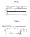
- a vibration occurs which is subjected to an amplitude modulation involved in the operation such as the opening/closing of a suction valve or an exhaust valve and an explosive combustion (see Fig. 21 ). Since the vibration at this point occurs periodically for every rotational period, in an envelope spectrum, the rotational frequency and a high-order component thereof occur (see Fig. 22 ).
Landscapes
- Physics & Mathematics (AREA)
- General Physics & Mathematics (AREA)
- Acoustics & Sound (AREA)
- Measurement Of Mechanical Vibrations Or Ultrasonic Waves (AREA)
- Testing Of Devices, Machine Parts, Or Other Structures Thereof (AREA)
Applications Claiming Priority (2)
| Application Number | Priority Date | Filing Date | Title |
|---|---|---|---|
| JP2010046767 | 2010-03-03 | ||
| PCT/JP2011/053734 WO2011108391A1 (fr) | 2010-03-03 | 2011-02-21 | Procédé et appareil pour diagnostiquer l'état d'un coussinet |
Publications (4)
| Publication Number | Publication Date |
|---|---|
| EP2543977A1 true EP2543977A1 (fr) | 2013-01-09 |
| EP2543977A4 EP2543977A4 (fr) | 2014-08-27 |
| EP2543977B1 EP2543977B1 (fr) | 2019-05-01 |
| EP2543977B8 EP2543977B8 (fr) | 2019-06-26 |
Family
ID=44542047
Family Applications (1)
| Application Number | Title | Priority Date | Filing Date |
|---|---|---|---|
| EP11750503.2A Active EP2543977B8 (fr) | 2010-03-03 | 2011-02-21 | Procédé de diagnostic et dispositif de diagnostic pour un palier lisse |
Country Status (7)
| Country | Link |
|---|---|
| US (1) | US9588015B2 (fr) |
| EP (1) | EP2543977B8 (fr) |
| JP (2) | JP5968217B2 (fr) |
| KR (1) | KR101497781B1 (fr) |
| CN (1) | CN102834701B (fr) |
| DK (1) | DK2543977T3 (fr) |
| WO (1) | WO2011108391A1 (fr) |
Cited By (4)
| Publication number | Priority date | Publication date | Assignee | Title |
|---|---|---|---|---|
| US11047768B2 (en) * | 2016-02-23 | 2021-06-29 | Ntn Corporation | Abnormality diagnosis device and abnormality diagnosis method |
| GB2602038A (en) * | 2020-12-16 | 2022-06-22 | Edwards Ltd | Bearing wear monitoring |
| EP4242156A1 (fr) * | 2022-03-08 | 2023-09-13 | Otis Elevator Company | Procédé et dispositif de détection de défaillance pour équipement d'alimentation d'ascenseur et système d'ascenseur |
| EP4043856A4 (fr) * | 2019-10-02 | 2023-10-11 | NTN Corporation | Dispositif d'analyse de vibrations et système de mesure de vibrations |
Families Citing this family (52)
| Publication number | Priority date | Publication date | Assignee | Title |
|---|---|---|---|---|
| KR101507929B1 (ko) * | 2013-09-03 | 2015-04-07 | 자동차부품연구원 | 자동차 허브 베어링 모니터링 시스템 및 모니터링 방법 |
| DE102013226049A1 (de) * | 2013-12-16 | 2015-06-18 | Siemens Aktiengesellschaft | Vorrichtung sowie Verfahren zum Erfassen des aktuellen Schädigungszustandes einer Maschine |
| US9739685B2 (en) | 2014-04-15 | 2017-08-22 | International Business Machines Corporation | Integrated, predictive vibration analysis of rotational machine within electronics rack |
| JP5943357B2 (ja) * | 2014-09-17 | 2016-07-05 | インターナショナル・ビジネス・マシーンズ・コーポレーションInternational Business Machines Corporation | 検出装置、検出方法、およびプログラム |
| JP6183346B2 (ja) * | 2014-12-10 | 2017-08-23 | 日本精工株式会社 | 異常診断装置、軸受、回転装置、産業機械及び車両 |
| CN104992714A (zh) * | 2015-05-22 | 2015-10-21 | 株洲联诚集团有限责任公司 | 一种电机异音的检测方法 |
| RU2623177C2 (ru) * | 2015-05-28 | 2017-06-22 | Федеральное государственное казенное военное образовательное учреждение высшего образования "Военный учебно-научный центр Военно-Морского Флота "Военно-морская академия имени Адмирала флота Советского Союза Н.Г. Кузнецова" | Способ контроля технического состояния подшипников качения |
| PL3472579T3 (pl) * | 2016-05-18 | 2024-02-05 | Industrial Consulting Automation Research Engineering (I-Care) | Analiza nadpróbkowanych sygnałów drgań o wysokiej częstotliwości |
| JP6854595B2 (ja) * | 2016-05-31 | 2021-04-07 | 旭化成エンジニアリング株式会社 | ディーゼルエンジンのすべり軸受の診断装置 |
| US11314241B2 (en) * | 2016-06-07 | 2022-04-26 | Mitsubishi Electric Corporation | Abnormality diagnosis apparatus and abnormality diagnosis method |
| DE112017002846T5 (de) * | 2016-06-07 | 2019-02-28 | Mitsubishi Electric Corporation | Vorrichtung zur Abnormalitätsdiagnose und Verfahren zur Abnormalitätsdiagnose |
| CN106769031B (zh) * | 2016-11-14 | 2019-03-26 | 西安交通大学 | 一种基于自相关零点计数的风机轴承阶变信号识别方法 |
| US11513000B2 (en) * | 2016-12-12 | 2022-11-29 | Rorze Corporation | Waveform analysis device and waveform analysis method |
| RU2757338C2 (ru) * | 2017-02-22 | 2021-10-13 | СиЭмТиИ ДЕВЕЛОПМЕНТ ЛИМИТЕД | Система и способ оптико-акустического контроля |
| US10816437B2 (en) * | 2017-03-22 | 2020-10-27 | General Electric Company | Contactless rotor state/speed measurement of x-ray tube |
| WO2019044575A1 (fr) * | 2017-08-31 | 2019-03-07 | Ntn株式会社 | Dispositif de surveillance d'état et procédé de surveillance d'état |
| JP7098399B2 (ja) * | 2017-08-31 | 2022-07-11 | Ntn株式会社 | 状態監視装置および状態監視方法 |
| JP7000135B2 (ja) * | 2017-11-24 | 2022-01-19 | オークマ株式会社 | 送り軸の異常診断方法及び異常診断装置 |
| CN108007548B (zh) * | 2017-12-01 | 2020-02-07 | 华能国际电力股份有限公司 | 一种通过扫频诊断设备故障的方法 |
| US20210062803A1 (en) * | 2018-01-24 | 2021-03-04 | Magnetic Pumping Solutions Llc | Method and system for monitoring the condition of rotating systems |
| CN108593296B (zh) * | 2018-04-26 | 2020-01-31 | 济南大学 | 一种基于倒谱伪边距的轴承单点故障诊断方法 |
| KR102560570B1 (ko) * | 2018-10-30 | 2023-07-28 | 한국전력공사 | 플랜트 공정 제어루프의 오실레이션 진단 방법 및 이를 이용한 오실레이션 진단 장치 |
| US11184690B2 (en) * | 2018-12-07 | 2021-11-23 | Itt Manufacturing Enterprises Llc | Embedded system for vibration detection and analysis |
| CN109579981B (zh) * | 2018-12-28 | 2023-11-10 | 重庆江增船舶重工有限公司 | 一种径向滑动轴承的振动监测装置及方法 |
| CN111780977B (zh) * | 2019-03-18 | 2022-03-11 | 中国航发商用航空发动机有限责任公司 | 叶片刮磨监测方法及监测系统 |
| JP7224234B2 (ja) * | 2019-04-25 | 2023-02-17 | Thk株式会社 | 異常診断システム、及び異常診断方法 |
| CN110427708B (zh) * | 2019-08-06 | 2022-09-30 | 上海海事大学 | 基于振动信号的润滑状态确定方法、装置及计算机存储介质 |
| DE102019122642A1 (de) * | 2019-08-22 | 2021-02-25 | Dickow Pumpen GmbH & Co. KG. | Vorrichtung und Verfahren zur Überwachung wenigstens eines Gleitlagers |
| CN110595597B (zh) * | 2019-10-24 | 2024-03-12 | 国网湖南省电力有限公司 | 油浸式变压器内部噪声监测传感器安装设备及其修正方法 |
| GB202000742D0 (en) * | 2020-01-17 | 2020-03-04 | Univ Of Saltford | Vibro-electric condition monitoring |
| JP7379241B2 (ja) * | 2020-03-25 | 2023-11-14 | 三菱重工業株式会社 | 回転機の診断監視装置及び方法 |
| JP7381390B2 (ja) * | 2020-04-13 | 2023-11-15 | 株式会社日立製作所 | 異常診断装置、および、保守管理システム |
| JP7585640B2 (ja) * | 2020-07-21 | 2024-11-19 | セイコーエプソン株式会社 | 信号処理方法及び信号処理装置 |
| CA3200978A1 (fr) * | 2020-11-09 | 2022-05-12 | Hengstler Gmbh | Detection de glissement d'accouplement dans systemes de codeurs rotatifs |
| CN112836574B (zh) * | 2020-12-30 | 2023-08-29 | 江苏光为传感设备有限公司 | 一种基于谱相似度的光纤振动事件识别方法 |
| CN113702045B (zh) * | 2021-08-16 | 2023-12-05 | 人本股份有限公司 | 滚动轴承的自相关函数振动监控方法 |
| DE102021211493A1 (de) * | 2021-10-12 | 2023-04-13 | Aktiebolaget Skf | Vorrichtung und Verfahren zum Abschätzen einer Last in einem Lager |
| WO2022152336A1 (fr) * | 2021-10-26 | 2022-07-21 | Západočeská Univerzita V Plzni | Procédé de surveillance de vibration d'aube de turbine |
| CN114417910B (zh) * | 2021-12-07 | 2025-09-09 | 上海朋禾智能科技有限公司 | 一种转动设备的故障监测方法 |
| CN114201831B (zh) * | 2021-12-13 | 2024-08-20 | 大连理工大学 | 一种基于振动信号实时采集的滚动轴承工况量化分析方法 |
| JP7588755B2 (ja) * | 2022-02-24 | 2024-11-22 | 三菱電機株式会社 | 潤滑状態判定装置 |
| JP2023152346A (ja) * | 2022-04-04 | 2023-10-17 | 株式会社神戸製鋼所 | 滑り軸受診断支援装置、該方法および該プログラム |
| CN114781467B (zh) * | 2022-06-22 | 2022-09-06 | 济南嘉宏科技有限责任公司 | 一种基于振动相似度的故障检测方法 |
| CN115560846A (zh) * | 2022-09-09 | 2023-01-03 | 上海电气风电集团股份有限公司 | 齿轮箱状态检测方法、系统和计算机可读存储介质 |
| CN115575122B (zh) * | 2022-09-27 | 2026-02-06 | 西门子爱克斯射线真空技术(无锡)有限公司 | 一种液态轴承异常判断方法及装置 |
| SE546721C2 (en) * | 2022-12-02 | 2025-02-11 | Cellwood Machinery Ab | Gap width monitoring |
| CN116183228B (zh) * | 2023-03-07 | 2023-08-11 | 榆林学院 | 一种滚动轴承故障模拟试验装置 |
| CN116358870A (zh) * | 2023-03-24 | 2023-06-30 | 上海士翌数字技术有限公司 | 一种齿轮箱滚动轴承故障分析方法及系统 |
| CN116861311A (zh) * | 2023-07-04 | 2023-10-10 | 北京航空航天大学 | 基于倒谱编辑与谱平均负熵的轴承定量诊断方法 |
| DE102023126529B3 (de) | 2023-09-28 | 2025-03-27 | Ks Gleitlager Gmbh | Verfahren und Vorrichtung zum Bestimmen eines Verschleißzustands einer Gleitlageranordnung |
| CN118209334B (zh) * | 2024-05-21 | 2024-08-06 | 山东轴研精密轴承有限公司 | 一种汽车车轮毂轴承单元动态能耗评估方法 |
| CN118641204B (zh) * | 2024-08-09 | 2024-11-15 | 石家庄铁道大学 | 轴承的性能退化起始点检测方法、装置、设备及存储介质 |
Family Cites Families (21)
| Publication number | Priority date | Publication date | Assignee | Title |
|---|---|---|---|---|
| JPH0718746B2 (ja) * | 1985-05-21 | 1995-03-06 | 株式会社明電舍 | 回転体の異常検出装置 |
| JPH03191859A (ja) * | 1989-12-20 | 1991-08-21 | Toyota Motor Corp | クラック検出装置 |
| JP3020349B2 (ja) * | 1992-05-29 | 2000-03-15 | 北海道大学長 | 異常検出方法及び装置 |
| JPH08261817A (ja) | 1995-03-20 | 1996-10-11 | Toshiba Corp | 回転機械のラビング判定方法およびその装置 |
| JPH1183617A (ja) * | 1997-09-12 | 1999-03-26 | Mitsubishi Heavy Ind Ltd | 較正方法、及び振動解析装置 |
| DE69837847T2 (de) * | 1998-03-16 | 2008-02-07 | Central Japan Railway Co., Nagoya | Vorrichtung zur prüfung der hauptmotorenlager in schienenfahrzeugen |
| JP2000214052A (ja) * | 1999-01-28 | 2000-08-04 | Nichiha Corp | 異常音検出システム及び記録媒体 |
| US7277822B2 (en) * | 2000-09-28 | 2007-10-02 | Blemel Kenneth G | Embedded system for diagnostics and prognostics of conduits |
| DE10144076A1 (de) * | 2001-09-07 | 2003-03-27 | Daimler Chrysler Ag | Vorrichtung und Verfahren zur Früherkennung und Vorhersage von Aggregateschädigungen |
| US6681634B2 (en) * | 2001-12-11 | 2004-01-27 | Itt Manufacturing Enterprises, Inc. | Bearing defect detection using time synchronous averaging (TSA) of an enveloped accelerometer signal |
| JP3382240B1 (ja) | 2002-06-12 | 2003-03-04 | 隆義 山本 | 対象設備を診断する方法、コンピュータプログラム、および対象設備を診断するための装置 |
| US7027953B2 (en) * | 2002-12-30 | 2006-04-11 | Rsl Electronics Ltd. | Method and system for diagnostics and prognostics of a mechanical system |
| WO2006030786A1 (fr) | 2004-09-13 | 2006-03-23 | Nsk Ltd. | Dispositif de diagnostic d’anomalie et procede de diagnostic d’anomalie |
| WO2006043511A1 (fr) * | 2004-10-18 | 2006-04-27 | Nsk Ltd. | Systeme de diagnostic d’anomalie pour une machinerie |
| JP4848803B2 (ja) * | 2006-03-13 | 2011-12-28 | 日本精工株式会社 | 異常診断装置、回転装置及び異常診断方法 |
| CN1825082B (zh) * | 2006-03-31 | 2010-04-14 | 洛阳轴研科技股份有限公司 | 滚动轴承故障自动诊断系统 |
| JP4003088B2 (ja) * | 2006-12-20 | 2007-11-07 | 日本精工株式会社 | 回転体の異常診断方法及び装置 |
| JP5146008B2 (ja) * | 2007-06-11 | 2013-02-20 | 日本精工株式会社 | 異常診断装置、及び異常診断方法 |
| KR20070105288A (ko) * | 2007-08-01 | 2007-10-30 | 순천대학교 산학협력단 | LabVIEW를 이용한 디젤엔진발전기의 베어링 고장진단 |
| KR101429952B1 (ko) * | 2008-01-30 | 2014-08-13 | 제이에프이 어드밴테크 가부시키가이샤 | 베어링의 진단 시스템 |
| DE102008021360A1 (de) * | 2008-04-29 | 2009-11-05 | Siemens Aktiengesellschaft | Verfahren und Vorrichtung zum Erkennen eines Lagerschadens |
-
2011
- 2011-02-21 EP EP11750503.2A patent/EP2543977B8/fr active Active
- 2011-02-21 US US13/582,288 patent/US9588015B2/en active Active
- 2011-02-21 DK DK11750503.2T patent/DK2543977T3/da active
- 2011-02-21 CN CN201180011831.3A patent/CN102834701B/zh active Active
- 2011-02-21 JP JP2012503071A patent/JP5968217B2/ja active Active
- 2011-02-21 WO PCT/JP2011/053734 patent/WO2011108391A1/fr not_active Ceased
- 2011-02-21 KR KR1020127023031A patent/KR101497781B1/ko active Active
-
2016
- 2016-01-08 JP JP2016002455A patent/JP6111347B2/ja active Active
Cited By (4)
| Publication number | Priority date | Publication date | Assignee | Title |
|---|---|---|---|---|
| US11047768B2 (en) * | 2016-02-23 | 2021-06-29 | Ntn Corporation | Abnormality diagnosis device and abnormality diagnosis method |
| EP4043856A4 (fr) * | 2019-10-02 | 2023-10-11 | NTN Corporation | Dispositif d'analyse de vibrations et système de mesure de vibrations |
| GB2602038A (en) * | 2020-12-16 | 2022-06-22 | Edwards Ltd | Bearing wear monitoring |
| EP4242156A1 (fr) * | 2022-03-08 | 2023-09-13 | Otis Elevator Company | Procédé et dispositif de détection de défaillance pour équipement d'alimentation d'ascenseur et système d'ascenseur |
Also Published As
| Publication number | Publication date |
|---|---|
| JPWO2011108391A1 (ja) | 2013-06-24 |
| KR101497781B1 (ko) | 2015-03-02 |
| KR20120129938A (ko) | 2012-11-28 |
| HK1179338A1 (en) | 2013-09-27 |
| US9588015B2 (en) | 2017-03-07 |
| EP2543977B1 (fr) | 2019-05-01 |
| CN102834701B (zh) | 2015-04-08 |
| US20130006551A1 (en) | 2013-01-03 |
| EP2543977A4 (fr) | 2014-08-27 |
| WO2011108391A1 (fr) | 2011-09-09 |
| EP2543977B8 (fr) | 2019-06-26 |
| JP6111347B2 (ja) | 2017-04-05 |
| DK2543977T3 (da) | 2019-06-11 |
| JP5968217B2 (ja) | 2016-08-10 |
| JP2016048267A (ja) | 2016-04-07 |
| CN102834701A (zh) | 2012-12-19 |
Similar Documents
| Publication | Publication Date | Title |
|---|---|---|
| EP2543977B1 (fr) | Procédé de diagnostic et dispositif de diagnostic pour un palier lisse | |
| Lei et al. | Fault diagnosis of rotating machinery using an improved HHT based on EEMD and sensitive IMFs | |
| Yu et al. | An adaptive sensitive frequency band selection method for empirical wavelet transform and its application in bearing fault diagnosis | |
| US10352823B2 (en) | Methods of analysing apparatus | |
| CN114201831A (zh) | 一种基于振动信号实时采集的滚动轴承工况量化分析方法 | |
| CN113944600B (zh) | 一种利用应力波技术检测风机主轴承故障的方法和系统 | |
| JP6854595B2 (ja) | ディーゼルエンジンのすべり軸受の診断装置 | |
| JP2011180082A (ja) | すべり軸受の診断方法および診断装置 | |
| Kim et al. | Effective band-selection algorithm for rolling element bearing diagnosis using AE sensor data under noisy conditions: SJ Kim et al. | |
| CN120740988B (zh) | 一种发动机运行状态监测方法及系统 | |
| CN112577722B (zh) | 基于平方包络和零频率谐振器的弱故障诊断方法 | |
| Kriston et al. | Application of vibro-acoustic methods in failure diagnostics | |
| JP7713696B2 (ja) | 転がり軸受の異常診断方法、および、異常診断用コンピュータプログラム | |
| CN119414232A (zh) | 一种双三相永磁同步电机的故障诊断方法及系统 | |
| Thanagasundram et al. | Autoregressive based diagnostics scheme for detection of bearing faults | |
| Kluczyk et al. | Vibration diagnostics of the naval propulsion systems | |
| Vernekar et al. | Fault detection of gear using spectrum and cepstrum analysis | |
| Chen et al. | Diagnosis of machinery fault status using transient vibration signal parameters | |
| Lim et al. | Improved blade fault diagnosis using discrete Blade Passing Energy Packet and rotor dynamics wavelet analysis | |
| JPH07229815A (ja) | エンジン診断装置 | |
| Grządziela et al. | An application of order tracking procedure for diagnosis technical state of rotor system in shut-down process | |
| CN119643145B (zh) | 基于脉冲范数振动烈度的滚动轴承早期故障诊断方法 | |
| HK1179338B (en) | Method and apparatus for diagnosing bushing | |
| Kumar et al. | A Review paper on Vibration-Based Fault Diagnosis of Rolling Element Bearings | |
| Gholap et al. | Condition monitoring of two-stage spur gearbox using vibration signature spectrum analysis |
Legal Events
| Date | Code | Title | Description |
|---|---|---|---|
| PUAI | Public reference made under article 153(3) epc to a published international application that has entered the european phase |
Free format text: ORIGINAL CODE: 0009012 |
|
| 17P | Request for examination filed |
Effective date: 20120904 |
|
| AK | Designated contracting states |
Kind code of ref document: A1 Designated state(s): AL AT BE BG CH CY CZ DE DK EE ES FI FR GB GR HR HU IE IS IT LI LT LU LV MC MK MT NL NO PL PT RO RS SE SI SK SM TR |
|
| DAX | Request for extension of the european patent (deleted) | ||
| A4 | Supplementary search report drawn up and despatched |
Effective date: 20140724 |
|
| RIC1 | Information provided on ipc code assigned before grant |
Ipc: G01H 1/14 20060101AFI20140718BHEP Ipc: G01M 13/04 20060101ALI20140718BHEP |
|
| 17Q | First examination report despatched |
Effective date: 20140912 |
|
| GRAP | Despatch of communication of intention to grant a patent |
Free format text: ORIGINAL CODE: EPIDOSNIGR1 |
|
| STAA | Information on the status of an ep patent application or granted ep patent |
Free format text: STATUS: GRANT OF PATENT IS INTENDED |
|
| INTG | Intention to grant announced |
Effective date: 20181018 |
|
| GRAS | Grant fee paid |
Free format text: ORIGINAL CODE: EPIDOSNIGR3 |
|
| GRAJ | Information related to disapproval of communication of intention to grant by the applicant or resumption of examination proceedings by the epo deleted |
Free format text: ORIGINAL CODE: EPIDOSDIGR1 |
|
| GRAL | Information related to payment of fee for publishing/printing deleted |
Free format text: ORIGINAL CODE: EPIDOSDIGR3 |
|
| STAA | Information on the status of an ep patent application or granted ep patent |
Free format text: STATUS: EXAMINATION IS IN PROGRESS |
|
| REG | Reference to a national code |
Ref country code: DE Ref legal event code: R079 Ref document number: 602011058517 Country of ref document: DE Free format text: PREVIOUS MAIN CLASS: G01H0017000000 Ipc: G01M0013045000 |
|
| GRAR | Information related to intention to grant a patent recorded |
Free format text: ORIGINAL CODE: EPIDOSNIGR71 |
|
| STAA | Information on the status of an ep patent application or granted ep patent |
Free format text: STATUS: GRANT OF PATENT IS INTENDED |
|
| GRAA | (expected) grant |
Free format text: ORIGINAL CODE: 0009210 |
|
| STAA | Information on the status of an ep patent application or granted ep patent |
Free format text: STATUS: THE PATENT HAS BEEN GRANTED |
|
| INTC | Intention to grant announced (deleted) | ||
| RIC1 | Information provided on ipc code assigned before grant |
Ipc: G01H 1/14 20060101ALI20190304BHEP Ipc: G01M 13/045 20190101AFI20190304BHEP |
|
| INTG | Intention to grant announced |
Effective date: 20190320 |
|
| AK | Designated contracting states |
Kind code of ref document: B1 Designated state(s): AL AT BE BG CH CY CZ DE DK EE ES FI FR GB GR HR HU IE IS IT LI LT LU LV MC MK MT NL NO PL PT RO RS SE SI SK SM TR |
|
| REG | Reference to a national code |
Ref country code: GB Ref legal event code: FG4D |
|
| REG | Reference to a national code |
Ref country code: CH Ref legal event code: EP Ref country code: AT Ref legal event code: REF Ref document number: 1127587 Country of ref document: AT Kind code of ref document: T Effective date: 20190515 |
|
| REG | Reference to a national code |
Ref country code: DE Ref legal event code: R096 Ref document number: 602011058517 Country of ref document: DE |
|
| REG | Reference to a national code |
Ref country code: IE Ref legal event code: FG4D |
|
| REG | Reference to a national code |
Ref country code: CH Ref legal event code: PK Free format text: BERICHTIGUNG B8 |
|
| RAP2 | Party data changed (patent owner data changed or rights of a patent transferred) |
Owner name: ASAHI KASEI ENGINEERING CORPORATION |
|
| REG | Reference to a national code |
Ref country code: DE Ref legal event code: R082 Ref document number: 602011058517 Country of ref document: DE Representative=s name: DOMPATENT VON KREISLER SELTING WERNER - PARTNE, DE Ref country code: DK Ref legal event code: T3 Effective date: 20190607 |
|
| REG | Reference to a national code |
Ref country code: CH Ref legal event code: NV Representative=s name: KASCHE AND PARTNER AG, CH |
|
| REG | Reference to a national code |
Ref country code: NO Ref legal event code: T2 Effective date: 20190501 |
|
| REG | Reference to a national code |
Ref country code: NL Ref legal event code: MP Effective date: 20190501 |
|
| REG | Reference to a national code |
Ref country code: LT Ref legal event code: MG4D |
|
| PG25 | Lapsed in a contracting state [announced via postgrant information from national office to epo] |
Ref country code: LT Free format text: LAPSE BECAUSE OF FAILURE TO SUBMIT A TRANSLATION OF THE DESCRIPTION OR TO PAY THE FEE WITHIN THE PRESCRIBED TIME-LIMIT Effective date: 20190501 Ref country code: SE Free format text: LAPSE BECAUSE OF FAILURE TO SUBMIT A TRANSLATION OF THE DESCRIPTION OR TO PAY THE FEE WITHIN THE PRESCRIBED TIME-LIMIT Effective date: 20190501 Ref country code: HR Free format text: LAPSE BECAUSE OF FAILURE TO SUBMIT A TRANSLATION OF THE DESCRIPTION OR TO PAY THE FEE WITHIN THE PRESCRIBED TIME-LIMIT Effective date: 20190501 Ref country code: AL Free format text: LAPSE BECAUSE OF FAILURE TO SUBMIT A TRANSLATION OF THE DESCRIPTION OR TO PAY THE FEE WITHIN THE PRESCRIBED TIME-LIMIT Effective date: 20190501 Ref country code: PT Free format text: LAPSE BECAUSE OF FAILURE TO SUBMIT A TRANSLATION OF THE DESCRIPTION OR TO PAY THE FEE WITHIN THE PRESCRIBED TIME-LIMIT Effective date: 20190901 Ref country code: ES Free format text: LAPSE BECAUSE OF FAILURE TO SUBMIT A TRANSLATION OF THE DESCRIPTION OR TO PAY THE FEE WITHIN THE PRESCRIBED TIME-LIMIT Effective date: 20190501 Ref country code: NL Free format text: LAPSE BECAUSE OF FAILURE TO SUBMIT A TRANSLATION OF THE DESCRIPTION OR TO PAY THE FEE WITHIN THE PRESCRIBED TIME-LIMIT Effective date: 20190501 |
|
| PG25 | Lapsed in a contracting state [announced via postgrant information from national office to epo] |
Ref country code: GR Free format text: LAPSE BECAUSE OF FAILURE TO SUBMIT A TRANSLATION OF THE DESCRIPTION OR TO PAY THE FEE WITHIN THE PRESCRIBED TIME-LIMIT Effective date: 20190802 Ref country code: BG Free format text: LAPSE BECAUSE OF FAILURE TO SUBMIT A TRANSLATION OF THE DESCRIPTION OR TO PAY THE FEE WITHIN THE PRESCRIBED TIME-LIMIT Effective date: 20190801 Ref country code: RS Free format text: LAPSE BECAUSE OF FAILURE TO SUBMIT A TRANSLATION OF THE DESCRIPTION OR TO PAY THE FEE WITHIN THE PRESCRIBED TIME-LIMIT Effective date: 20190501 Ref country code: LV Free format text: LAPSE BECAUSE OF FAILURE TO SUBMIT A TRANSLATION OF THE DESCRIPTION OR TO PAY THE FEE WITHIN THE PRESCRIBED TIME-LIMIT Effective date: 20190501 |
|
| REG | Reference to a national code |
Ref country code: AT Ref legal event code: MK05 Ref document number: 1127587 Country of ref document: AT Kind code of ref document: T Effective date: 20190501 |
|
| PG25 | Lapsed in a contracting state [announced via postgrant information from national office to epo] |
Ref country code: IS Free format text: LAPSE BECAUSE OF FAILURE TO SUBMIT A TRANSLATION OF THE DESCRIPTION OR TO PAY THE FEE WITHIN THE PRESCRIBED TIME-LIMIT Effective date: 20190901 |
|
| PG25 | Lapsed in a contracting state [announced via postgrant information from national office to epo] |
Ref country code: EE Free format text: LAPSE BECAUSE OF FAILURE TO SUBMIT A TRANSLATION OF THE DESCRIPTION OR TO PAY THE FEE WITHIN THE PRESCRIBED TIME-LIMIT Effective date: 20190501 Ref country code: SK Free format text: LAPSE BECAUSE OF FAILURE TO SUBMIT A TRANSLATION OF THE DESCRIPTION OR TO PAY THE FEE WITHIN THE PRESCRIBED TIME-LIMIT Effective date: 20190501 Ref country code: AT Free format text: LAPSE BECAUSE OF FAILURE TO SUBMIT A TRANSLATION OF THE DESCRIPTION OR TO PAY THE FEE WITHIN THE PRESCRIBED TIME-LIMIT Effective date: 20190501 Ref country code: CZ Free format text: LAPSE BECAUSE OF FAILURE TO SUBMIT A TRANSLATION OF THE DESCRIPTION OR TO PAY THE FEE WITHIN THE PRESCRIBED TIME-LIMIT Effective date: 20190501 Ref country code: RO Free format text: LAPSE BECAUSE OF FAILURE TO SUBMIT A TRANSLATION OF THE DESCRIPTION OR TO PAY THE FEE WITHIN THE PRESCRIBED TIME-LIMIT Effective date: 20190501 |
|
| REG | Reference to a national code |
Ref country code: DE Ref legal event code: R097 Ref document number: 602011058517 Country of ref document: DE |
|
| PG25 | Lapsed in a contracting state [announced via postgrant information from national office to epo] |
Ref country code: SM Free format text: LAPSE BECAUSE OF FAILURE TO SUBMIT A TRANSLATION OF THE DESCRIPTION OR TO PAY THE FEE WITHIN THE PRESCRIBED TIME-LIMIT Effective date: 20190501 Ref country code: IT Free format text: LAPSE BECAUSE OF FAILURE TO SUBMIT A TRANSLATION OF THE DESCRIPTION OR TO PAY THE FEE WITHIN THE PRESCRIBED TIME-LIMIT Effective date: 20190501 |
|
| PLBE | No opposition filed within time limit |
Free format text: ORIGINAL CODE: 0009261 |
|
| STAA | Information on the status of an ep patent application or granted ep patent |
Free format text: STATUS: NO OPPOSITION FILED WITHIN TIME LIMIT |
|
| PG25 | Lapsed in a contracting state [announced via postgrant information from national office to epo] |
Ref country code: TR Free format text: LAPSE BECAUSE OF FAILURE TO SUBMIT A TRANSLATION OF THE DESCRIPTION OR TO PAY THE FEE WITHIN THE PRESCRIBED TIME-LIMIT Effective date: 20190501 |
|
| 26N | No opposition filed |
Effective date: 20200204 |
|
| PG25 | Lapsed in a contracting state [announced via postgrant information from national office to epo] |
Ref country code: PL Free format text: LAPSE BECAUSE OF FAILURE TO SUBMIT A TRANSLATION OF THE DESCRIPTION OR TO PAY THE FEE WITHIN THE PRESCRIBED TIME-LIMIT Effective date: 20190501 |
|
| PG25 | Lapsed in a contracting state [announced via postgrant information from national office to epo] |
Ref country code: SI Free format text: LAPSE BECAUSE OF FAILURE TO SUBMIT A TRANSLATION OF THE DESCRIPTION OR TO PAY THE FEE WITHIN THE PRESCRIBED TIME-LIMIT Effective date: 20190501 |
|
| REG | Reference to a national code |
Ref country code: BE Ref legal event code: MM Effective date: 20200229 |
|
| PG25 | Lapsed in a contracting state [announced via postgrant information from national office to epo] |
Ref country code: MC Free format text: LAPSE BECAUSE OF FAILURE TO SUBMIT A TRANSLATION OF THE DESCRIPTION OR TO PAY THE FEE WITHIN THE PRESCRIBED TIME-LIMIT Effective date: 20190501 Ref country code: LU Free format text: LAPSE BECAUSE OF NON-PAYMENT OF DUE FEES Effective date: 20200221 |
|
| PG25 | Lapsed in a contracting state [announced via postgrant information from national office to epo] |
Ref country code: IE Free format text: LAPSE BECAUSE OF NON-PAYMENT OF DUE FEES Effective date: 20200221 |
|
| PG25 | Lapsed in a contracting state [announced via postgrant information from national office to epo] |
Ref country code: BE Free format text: LAPSE BECAUSE OF NON-PAYMENT OF DUE FEES Effective date: 20200229 |
|
| PG25 | Lapsed in a contracting state [announced via postgrant information from national office to epo] |
Ref country code: FR Free format text: LAPSE BECAUSE OF NON-PAYMENT OF DUE FEES Effective date: 20200302 |
|
| PG25 | Lapsed in a contracting state [announced via postgrant information from national office to epo] |
Ref country code: MT Free format text: LAPSE BECAUSE OF FAILURE TO SUBMIT A TRANSLATION OF THE DESCRIPTION OR TO PAY THE FEE WITHIN THE PRESCRIBED TIME-LIMIT Effective date: 20190501 Ref country code: CY Free format text: LAPSE BECAUSE OF FAILURE TO SUBMIT A TRANSLATION OF THE DESCRIPTION OR TO PAY THE FEE WITHIN THE PRESCRIBED TIME-LIMIT Effective date: 20190501 |
|
| PG25 | Lapsed in a contracting state [announced via postgrant information from national office to epo] |
Ref country code: MK Free format text: LAPSE BECAUSE OF FAILURE TO SUBMIT A TRANSLATION OF THE DESCRIPTION OR TO PAY THE FEE WITHIN THE PRESCRIBED TIME-LIMIT Effective date: 20190501 |
|
| P01 | Opt-out of the competence of the unified patent court (upc) registered |
Effective date: 20230523 |
|
| PGFP | Annual fee paid to national office [announced via postgrant information from national office to epo] |
Ref country code: FI Payment date: 20240219 Year of fee payment: 14 Ref country code: CH Payment date: 20240301 Year of fee payment: 14 |
|
| PGFP | Annual fee paid to national office [announced via postgrant information from national office to epo] |
Ref country code: NO Payment date: 20240222 Year of fee payment: 14 Ref country code: DK Payment date: 20240223 Year of fee payment: 14 |
|
| PGFP | Annual fee paid to national office [announced via postgrant information from national office to epo] |
Ref country code: GB Payment date: 20250219 Year of fee payment: 15 |
|
| REG | Reference to a national code |
Ref country code: DK Ref legal event code: EBP Effective date: 20250228 |
|
| REG | Reference to a national code |
Ref country code: CH Ref legal event code: PL |
|
| PG25 | Lapsed in a contracting state [announced via postgrant information from national office to epo] |
Ref country code: FI Free format text: LAPSE BECAUSE OF NON-PAYMENT OF DUE FEES Effective date: 20250221 |
|
| PG25 | Lapsed in a contracting state [announced via postgrant information from national office to epo] |
Ref country code: NO Free format text: LAPSE BECAUSE OF NON-PAYMENT OF DUE FEES Effective date: 20250228 |
|
| PG25 | Lapsed in a contracting state [announced via postgrant information from national office to epo] |
Ref country code: CH Free format text: LAPSE BECAUSE OF NON-PAYMENT OF DUE FEES Effective date: 20250228 |
|
| PG25 | Lapsed in a contracting state [announced via postgrant information from national office to epo] |
Ref country code: DK Free format text: LAPSE BECAUSE OF NON-PAYMENT OF DUE FEES Effective date: 20250228 |
|
| PGFP | Annual fee paid to national office [announced via postgrant information from national office to epo] |
Ref country code: DE Payment date: 20260218 Year of fee payment: 16 |