EP2543984B1 - Procédé de test de dureté - Google Patents
Procédé de test de dureté Download PDFInfo
- Publication number
- EP2543984B1 EP2543984B1 EP12174901.4A EP12174901A EP2543984B1 EP 2543984 B1 EP2543984 B1 EP 2543984B1 EP 12174901 A EP12174901 A EP 12174901A EP 2543984 B1 EP2543984 B1 EP 2543984B1
- Authority
- EP
- European Patent Office
- Prior art keywords
- specimen
- indentation
- test
- field lens
- image
- Prior art date
- Legal status (The legal status is an assumption and is not a legal conclusion. Google has not performed a legal analysis and makes no representation as to the accuracy of the status listed.)
- Active
Links
Images


Classifications
-
- G—PHYSICS
- G01—MEASURING; TESTING
- G01N—INVESTIGATING OR ANALYSING MATERIALS BY DETERMINING THEIR CHEMICAL OR PHYSICAL PROPERTIES
- G01N3/00—Investigating strength properties of solid materials by application of mechanical stress
- G01N3/40—Investigating hardness or rebound hardness
- G01N3/42—Investigating hardness or rebound hardness by performing impressions under a steady load by indentors, e.g. sphere, pyramid
-
- G—PHYSICS
- G01—MEASURING; TESTING
- G01N—INVESTIGATING OR ANALYSING MATERIALS BY DETERMINING THEIR CHEMICAL OR PHYSICAL PROPERTIES
- G01N3/00—Investigating strength properties of solid materials by application of mechanical stress
- G01N3/02—Details
- G01N3/06—Special adaptations of indicating or recording means
- G01N3/068—Special adaptations of indicating or recording means with optical indicating or recording means
-
- G—PHYSICS
- G01—MEASURING; TESTING
- G01N—INVESTIGATING OR ANALYSING MATERIALS BY DETERMINING THEIR CHEMICAL OR PHYSICAL PROPERTIES
- G01N2203/00—Investigating strength properties of solid materials by application of mechanical stress
- G01N2203/02—Details not specific for a particular testing method
- G01N2203/06—Indicating or recording means; Sensing means
- G01N2203/0641—Indicating or recording means; Sensing means using optical, X-ray, ultraviolet, infrared or similar detectors
- G01N2203/0647—Image analysis
Definitions
- the present invention relates to a hardness tester and a hardness testing method.
- hardness of a specimen has been measured based on dimensions of an indentation formed in a surface of the specimen.
- a hardness tester such as a Brinell hardness tester, a Vickers hardness tester, a Knoop hardness tester, and the like
- hardness of a specimen has been measured based on dimensions of an indentation formed in a surface of the specimen.
- the Vickers hardness tester an indenter with a four-sided pyramid-shaped tip is pressed onto a surface of the specimen, then the length of diagonal lines in the indentation formed on the specimen is measured with an optical microscope and the like. Then, based on the measured length of the diagonal lines in the indentation, hardness is calculated.
- a user in order not to generate measurement errors in measuring the dimensions of the indentation, a user must perform focusing on the surface of the specimen on which the indentation has been formed.
- a known example for the hardness tester in which focusing is performed designates a plurality of focus adjustment positions on the specimen on which the indentation has been formed. An image capturer is then operated so as to focus on the designated focus adjustment positions and an image of the indentation is captured. A degree of focus for the indentation in the designated focus adjustment position is calculated, then displayed on a monitor. Focus adjustment can thus be performed favorably (see, for example, Japanese Patent Laid-open Publication No. 2011-2247 ).
- a broad range image of a specimen S must be obtained in order to verify at which location on the specimen S the hardness test will be performed. For example, as shown in Fig. 6 , by combining a plurality of images A1 - A9 captured by displacing the specimen S in a horizontal direction, a broad range image G1 is obtained. Then, the broad range image G1 obtained is used to perform hardness testing.
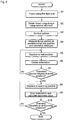
- a process after the broad range image G1 is obtained in the conventional hardness tester is described with reference to the flowchart of Fig. 8 and to the schematic diagram of Fig. 9 illustrating a tester main body 20 of a hardness tester.
- the setting of a test pattern refers to setting test conditions, a test start point, number of rows and columns, pitch, and the like.
- programming of test positions PI, P2, ... is performed.
- the hardness test begins automatically.
- the specimen S (specimen stage 2) is displaced so as to position the predetermined test positions (in the first cycle, the test start point) that opposes an indenter 14a (step S102).
- An indentation is then created at the test position (step S103).
- step S104 whether or not indentations have been created for all of the programmed test positions is determined.
- step S104: NO the process moves to step S102 and displaces the specimen S so as to position the next test position opposite the indenter 14a.
- step S104: YES the specimen S is displaced so as to position predetermined scanning positions (positions where indentation has been performed) opposite a field lens 15 used for indentation scanning (step S105).
- An autofocus process is then performed to focus on the scanning position (step S106).
- step S108 whether or not the indentation has been scanned in all scanning positions is determined.
- step S108: NO the process moves to step S105 and displaces the specimen S so as to position the next scanning position opposite the indenter 14a.
- step S108: YES the process ends.
- the broad range image G1 is obtained and test positions are programmed using the obtained broad range image Gl, thereby enabling a hardness test to be performed in the conventional hardness tester.
- an image having a high field of view (for example, A1 - A9 in Fig. 6 ) is obtained by using a low power field lens.
- a field depth C1 is deep.
- the field depth C1 may exceed an allowed range W1 for height of the specimen S during indentation. Accordingly, there is a risk that the field depth C1 may be positioned exceeding the allowed range W1 for height of the specimen S.
- an indentation is created in such a state, an unfavorable circumstance arises in which measurement errors are produced during indentation scanning.
- the field depth is shallow compared to the low power field lens and does not exceed the allowed range W1 for height of the specimen S. Accordingly, there is an advantage that accuracy is high for positioning the height of the specimen S.
- Fig. 6 because the field of view for an obtained image B1 is narrow, an extremely large number of images must be captured in order to obtain the broad range image Gl, incurring a great deal of time and effort.
- the present invention has as its advantage to provide a hardness testing method capable of positioning a specimen at an appropriate height and of shortening the execution time of a hardness test.
- the present invention is a hardness testing method in which hardness of a specimen is measured by loading a predetermined testing force from an indenter on a surface of the specimen placed on a specimen stage to form an indentation, then measuring dimensions of the indentation.
- the hardness testing method includes a focusing process, a first image capturing process, a test position setting process, a focus position memory controlling process, an indentation creating process, a second image capturing process, and/or a measuring process.
- the focusing process positions a first field lens above the specimen, then focuses on the surface of the specimen by changing a relative distance between the specimen stage and the first field lens.
- the first image capturing process positions a second field lens having a magnification power less than the first field lens above the specimen, then captures an image of the surface of the specimen with an image capturer.
- the test position setting process sets the test position in which the indentation will be formed based on image information of the surface of the specimen captured in the first image capturing process.
- the focus position memory controlling process positions the first field lens above the specimen, then measures a focus position at a predetermined test position among the test positions set with the test position setting process.
- the focus position memory controlling process then associates the measured focus position with the test position within a predetermined range and stores the information in a memory.
- the indentation creating process positions the indenter above the specimen and forms the indentation in the test position.
- the second image capturing process positions the first field lens above the specimen, then obtains the focus position associated with the test position from the memory and displaces the specimen based on the obtained focus position and the test position. Thereafter, the second image capturing process captures an image of the indentation formed in the indentation creating process with the image capturer.
- the measuring process measures the hardness of the specimen based on the indentation whose image was captured in the second image capturing process.
- height information (focus position) corresponding to the test position can be obtained at a step before the indentation is formed.
- the specimen can also be positioned at an appropriate height without performing an autofocus process at the time of indentation creation and at the time of indentation scanning. Therefore, execution time for hardness testing can be shortened, and also no negative circumstance arises in which measurement errors are produced during indentation scanning.
- the broad range image of the specimen is obtained, the low power second field lens can be used; thus, there is no need to obtain a large number of images, as compared to a case where the high power first field lens is used, and execution time for hardness testing can be shortened.
- the X direction in Fig. 1 will be the left-right direction
- the Y direction will be the front-back direction
- the Z direction will be the up-down direction
- the X-Y plane will be the horizontal plane.
- a hardness tester 100 is, for example, a Vickers hardness tester and includes, as shown in Figs. 1 and 2 , a tester main body 10, a controller 6, an operator 7, and a monitor 8.
- the tester main body 10 includes a hardness measurer 1, a specimen stage 2, an XY stage 3, an AF stage 4, and a lifting mechanism 5.
- the hardness measurer 1 performs hardness measurements on a specimen S.
- the specimen S is placed on the specimen stage 2.
- the XY stage 3 displaces the specimen stage 2.
- the AF stage 4 enables focusing on a surface of the specimen S.
- the lifting mechanism 5 raises and lowers the specimen stage 2 (the XY stage 3 and AF stage 4).
- the hardness measurer 1 for example and as shown in Fig. 3 , includes an illumination device 11, a CCD camera 12, an indenter shaft 14 provided with an indenter 14a, and field lenses 15.
- the illumination device 11 illuminates the surface of the specimen S.
- the CCD camera 12 captures an image of the surface of the specimen S.
- the hardness measurer 1 is further configured with a turret 16, on which the indenter shaft 14 and the field lenses 15 may be swapped by rotation.
- the illumination device 11 illuminates the surface of the specimen S by irradiating light thereon.
- the light irradiated from the illumination device 11 reaches the surface of the specimen S via a lens 1a, a half mirror 1d, a mirror 1e, and the field lenses 15.
- the CCD camera 12 captures an image of the surface of the specimen S and of the indentation formed thereon by the indenter 14a to obtain image data, based on reflected light input from the surface of the specimen S via the field lenses 15, the mirror 1e, the half mirror Id, a mirror 1g, and a lens 1h.
- the CCD camera 12 then outputs the image data to the controller 6 via a frame grabber 17 which is able to simultaneously accumulate and store image data for a plurality of frames. Accordingly, the CCD camera 12 acts as the image capturer.
- the indenter shaft 14 is displaced toward the specimen S resting on the specimen stage 2 and the indenter 14a provided to the tip thereof is pressed onto the surface of the specimen S with a predetermined testing force by a load mechanism (not shown in the drawings) driven according to a control signal output by the controller 6.
- the field lenses 15 are collective lenses configured with differing powers of magnification and are plurally supported on a bottom face of the turret 16.
- the field lenses 15 are placed above the specimen S by rotation of the turret 16, and thereby uniformly irradiate light irradiated from the illumination device 11 onto the surface of the specimen S.
- the field lenses 15 include a high power field lens (first field lens) 15a and a low power field lens (second field lens) 15b having a magnification power less than the high power field lens 15a.
- the high power field lens 15a specifically, is preferably a lens having a magnification power of twenty times or greater.
- the low power field lens 15b is preferably a lens having a magnification power of five times or less.
- magnification power is five times or less, an image having a high field of view can be obtained. Therefore, the broad range image G1 can be easily obtained.
- the indenter shaft 14 and the plurality of field lenses 15 are mounted to the bottom face of the turret 16.
- the turret 16 is configured to enable switching between the indenter shaft 14 and one of the field lenses 15 to position the same above the specimen S by rotating the turret 16 around the Z-axis direction. In other words, by positioning the indenter shaft 14 above the specimen S, the indentation can be formed in the surface of the specimen S, and by positioning the field lenses 15 above the specimen S, the formed indentation can be observed.
- the specimen stage 2 fixes the specimen S, resting on an upper surface thereof, in place with a specimen holder 2a.
- the XY stage 3 is driven by a drive mechanism (not shown in the drawings) in response to a control signal output by the controller 6.
- the XY stage 3 then displaces the specimen stage 2 in a direction (X-axis and Y-axis directions) perpendicular to a displacement direction (Z-axis direction) of the indenter 14a.
- the AF stage 4 is driven in response to a control signal output by the controller 6.
- the AF stage 4 then minutely raises and lowers the specimen stage 2 based on image data captured by the CCD camera 12 in order to focus on the surface of the specimen S.
- the lifting mechanism 5 is driven in response to a control signal output by the controller 6. By displacing the specimen stage 2 (the XY stage 3 and the AF stage 4) in the up-down direction, the lifting mechanism 5 changes the relative distance between the specimen stage 2 and the field lenses 15.
- the focuser is configured with the lifting mechanism 5 and the AF stage 4.
- the operator 7 is configured with a keyboard 71 and a mouse 72, and executes an input operation from the user when hardness testing is performed. Also, when a predetermined input operation is performed by the operator 7, a predetermined operation signal corresponding to the input operation is output to the controller 6.
- the operator 7 enables the user to select conditions determining a focus position for the indentation via the keyboard 71, the mouse 72, and the like. Further, the operator 7 can designate a range in which the specimen stage 2 (the lifting mechanism 5 and the AF stage 4) is displaced (a range of relative distance between the specimen stage 2 and the field lenses 15).
- the operator 7 also enables the user to input test condition values from a point when a hardness test is being executed by the hardness tester 100.
- the input test condition values are transmitted to the controller 6.
- test condition values are, for example, material of the specimen S, test force (N) loaded onto the specimen S by the indenter 14a, magnification power of the field lenses 15, and the like.
- the operator 7 also enables the user to select either of a manual mode in which determination of focus positions for the indentation is performed manually and an automatic mode in which the determination is performed automatically.
- the monitor 8 is, for example, configured with a display apparatus such as an LCD, and displays programmed conditions for a hardness test input with the operator 7, results of the hardness test, images of the surface of the specimen S and the indentation formed thereon captured by the CCD camera 12, and the like.
- a display apparatus such as an LCD
- the controller 6 includes a CPU (Central Processing Unit) 61, a RAM (Random Access Memory) 62, and a memory 63. By executing a predetermined program stored in the memory 63, the controller 6 performs operation control for the performance of a predetermined hardness test, and the like.
- a CPU Central Processing Unit
- RAM Random Access Memory
- the CPU 61 reads a processing program stored in the memory 63, then moves the program to the RAM 62 for execution. Thereby, the CPU 61 performs control on the entire hardness tester 100.
- the RAM 62 moves the processing program executed by the CPU 61 to a program storage region within the RAM 62.
- the RAM 62 stores input data, processing results generated when the processing program is executed, and the like in a data storage region.
- the memory 63 includes, for example, a memory medium (not shown in the drawings) storing programs, data, and the like.
- the memory medium is configured with a semiconductor memory and the like.
- the memory 63 stores various kinds of data for implementing an operation in which the CPU 61 controls the entire hardness tester 100, various kinds of processing programs, data processed by the execution of these programs, and the like. More specifically, the memory 63 stores, for example, an XY stage control program, an autofocus program, a hardness measurer control program, and the like.
- the CPU 61 By executing the XY stage control program stored in the memory 63, the CPU 61 displaces the XY stage 3 so as to position a predetermined region on the surface of the specimen S directly below the CCD camera 12. By executing the autofocus program stored in the memory 63, the CPU 61 also raises and lowers the AF stage 4 to perform autofocus with respect to the surface of the specimen S based on image information obtained by the CCD camera 12 of the hardness measurer 1.
- the CPU 61 By executing the hardness measurer control program stored in the memory 63, the CPU 61 also presses the indenter 14a onto the surface of the specimen S with a predetermined test force to form the indentation, measures the length of diagonal lines in the indentation based on image information for the surface of the specimen S generated by the CCD camera 12, and the like. In addition, the CPU 61 calculates the hardness of the specimen S based on the measured length of the diagonal lines in the indentation. The CPU 61 also displays on the monitor 8 image information for the surface of the specimen S generated by the CCD camera 12, calculation results for the hardness of the specimen S calculated by execution of the hardness measurer control program, and the like.
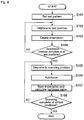
- the CPU 61 focuses on the surface of the specimen S using the high power field lens 15a (step S1: focusing process). Specifically, based on image data captured by the CCD camera 12 through the high power field lens 15a, the lifting mechanism 5 and the AF stage 4 (focuser) are controlled to minutely raise and lower the specimen stage 2. Autofocus is then performed with respect to a desired position on the surface of the specimen S, and positioning for the height of the specimen S is performed.
- the CPU 61 obtains the broad range image G1 of the specimen S using the low power field lens 15b (step 2: first image capturing process). Specifically, as shown in Fig. 6 , a plurality of images A1 - A9 are combined to obtain the broad range image G1, the images A1 - A9 obtained by displacing the specimen S in the horizontal direction and capturing the images with the CCD camera 12 through the low power field lens 15b.
- the CPU 61 sets a test pattern for the obtained broad range image G1 (step S3: test position setting process).
- the setting of the test pattern means setting test conditions (e.g., material of the specimen S, test force (N) loaded on the specimen S by the indenter 14a, magnification power of the field lenses 15, and the like), a test start point, number of rows and columns, pitch, and the like.
- test positions PI, P2, ... are programmed.
- the CPU 61 acts as a test position setter setting the test positions PI, P2, ... at which an indentation will be formed.
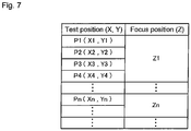
- step S4 focus position memory controlling process. Specifically, one point (or a plurality of points) is picked out for each predetermined range within the test positions set in step S3, then autofocus is performed at the picked-out test position. The height of the specimen S when in focus is measured as the focus position, and the measured focus position is associated with a test position within the predetermined range and stored in the memory 63. For example, as shown in Fig. 7 , one point (for example, test position PI) is picked out in a predetermined range (for example, a range that includes test positions PI - P4).
- a predetermined range for example, a range that includes test positions PI - P4
- a focus position Z1 for the picked-out test point PI is then associated with the test positions PI - P4 within the predetermined range and stored in the memory 63. That is, the CPU 61 measures through the high power field lens 15a the focus position at the predetermined test position from among the test positions set in step S3. The CPU 61 then associates the measured focus position with the test position within the predetermined range and stores the information in the memory 63. The CPU 61 thus acts as the focus position memory.
- the reason for picking out one point (or a plurality of points) for each predetermined range is because there is no need to measure focus positions for all test positions within the predetermined range for a predetermined range (i.e., a range in which no substantive difference is observed in focus positions for each test position). Another reason for picking out one point (or a plurality of points) for each predetermined range is because, by thinning out the measurements for focus positions as described above, the execution time for the hardness test can be shortened.
- the CPU 61 displaces the specimen S (specimen stage 2) so as to position the predetermined test position (in the first cycle, the test start point) opposite the indenter 14a (step S5). Because the focus position corresponding to the test position has been measured in step S4, the height of the specimen S is displaced to the focus position. Also, the CPU 61 forms the indentation at the test position with the indenter 14a (step S6: indentation creating process). In other words, the CPU 61 acts as the indentation creator forming the indentation at the test position with the indenter 14a.
- step S7 determines whether or not an indentation has been created for all of the measured test positions.
- step S7: NO the CPU 61 moves to step S5 and displaces the specimen S so as to position the next test position opposite the indenter 14a.
- step S7: YES the CPU 61 moves to the next step, step S8.
- the CPU 61 displaces the specimen S so as to position the predetermined scanning position (position where indentation has been performed) opposite the high power field lens 15a used for indentation scanning (step S8). Because the focus position corresponding to the scanning position has been measured in step S4, the focus position is obtained from the memory 63 and the height of the specimen S is displaced to the focus position.
- step S9 second image capturing process, measuring process.
- an image of the indentation is captured by the CCD camera 12 through the high power field lens 15a, then the length of diagonal lines in the indentation is measured based on the captured image data of the indentation.
- the hardness value for the specimen S is then calculated based on the length of the diagonal lines. That is, after displacing the specimen S based on the scanning position (test position and focus position), the CPU 61 acts as the image capture controller capturing an image of the indentation formed in step S6 with the CCD camera 12 through the high power field lens 15a.
- the CPU 61 also acts as the measurer measuring the hardness of the specimen based on the indentation whose image was captured in step S9.
- the CPU 61 determines whether or not the indentation has been scanned at all scanning positions (step S10).
- step S10: NO the CPU 61 moves to step S8 and displaces the specimen S so as to position the next scanning position opposite the indenter 14a.
- step S10: YES the CPU 61 ends the process.
- the hardness tester 100 includes the focuser (the lifting mechanism 5 and the AF stage 4), the CCD camera 12, the test position setter (the CPU 61), the focus position memory (CPU 61), the indentation creator (CPU 61), the image capture controller (CPU 61), and the measurer (CPU 61).
- the focuser lifting mechanism 5 and AF stage 4
- the CCD camera 12 captures an image of the surface of the specimen S through one of the high power field lens 15a and the low power field lens 15b.
- the test position setter (the CPU 61) sets the test positions PI, P2, ... at which the indentation will be formed based on image information (the broad range image Gl) for the surface of the specimen S captured by the CCD camera 12 through the low power field lens 15b.
- the focus position memory (CPU 61) measures a focus position through the high power field lens 15a at a predetermined test position among the test positions PI, P2, ... set by the test position setter, then associates the measured focus position with the test position within the predetermined range and stores the information in the memory 63.
- the indentation creator (CPU 61) forms the indentation at the test positions PI, P2, ... with the indenter 14a.
- the image capture controller (CPU 61) obtains the focus positions associated with the test positions PI, P2, ... from the memory 63, then displaces the specimen S based on the obtained focus positions and test positions PI, P2, .... Thereafter, the image capture controller (CPU 61) captures an image of the indentation formed by the indentation creator with the CCD camera 12 through the high power field lens 15a.
- the measurer (CPU 61) measures the hardness of the specimen S based on the indentation whose image has been captured by the control of the image capture controller. For this reason, height information (focus position) corresponding to a test position can be obtained at a stage before the indentation is formed.
- the specimen S can be positioned at an appropriate height without performing an autofocus process at the time of indentation creation and at the time of indentation scanning.
- execution time for the hardness test can be shortened and, in addition, a negative circumstance does not arise in which measurement errors are produced during indentation scanning.
- the low power field lens 15b having a high field of view can be used. Thus, there is no need to obtain a large number of images, and execution time for the hardness test can be shortened.
- the high power field lens 15a is a lens having a magnification power of twenty times or greater.
- the field depth is shallow and does not exceed the allowed range for height of the specimen S during indentation creation. Positioning accuracy for the height of the specimen S can also be improved.
- the low power field lens 15b is a lens having a magnification power of five times or less. Thus, images having a high field of view can be obtained, and the broad range image G1 can be easily obtained.
- step S8 shown in Fig. 5 the specimen S is displaced so as to position the predetermined scanning position opposite the high power field lens 15a, then the height of the specimen S is displaced to the focus position. Thereafter, without performing an autofocus process, an indentation scanning operation is performed.
- the present invention is not limited to this.
- focus positions are not measured at every test position. Therefore, even when the height of the specimen S is displaced to the focus position, there is a possibility that the degree of focus will be low for certain test positions. Imagining such a case, the degree of focus may be calculated during indentation scanning and, when the degree of focus is determined to be low, an autofocus process may also be performed.
- the present embodiment is not limited to this. So long as the present invention includes at least two field lenses 15 of different magnification powers, mid-power field lenses may also be added, for example, to the high power field lens 15a and the low power field lens 15b.
Landscapes
- Physics & Mathematics (AREA)
- Health & Medical Sciences (AREA)
- Life Sciences & Earth Sciences (AREA)
- Chemical & Material Sciences (AREA)
- Analytical Chemistry (AREA)
- Biochemistry (AREA)
- General Health & Medical Sciences (AREA)
- General Physics & Mathematics (AREA)
- Immunology (AREA)
- Pathology (AREA)
- Microscoopes, Condenser (AREA)
- Investigating Strength Of Materials By Application Of Mechanical Stress (AREA)
Claims (1)
- Procédé d'essai de dureté à l'aide d'un duromètre, dans lequel la dureté d'un échantillon (S) est mesurée par application d'une force d'essai prédéterminée à partir d'un pénétrateur (14a) sur une surface de l'échantillon (S) placé sur une platine porte-échantillon (2) pour former une empreinte, puis par mesure de dimensions de l'empreinte, le procédé comprenant les étapes consistant à :positionner (S1) une première lentille de champ (15a) au-dessus de l'échantillon (S), puis mettre au point sur la surface de l'échantillon (S) en modifiant une distance relative entre la platine porte-échantillon (2) et la première lentille de champ (15a) ;positionner une seconde lentille de champ (15b) ayant un grossissement inférieur à celui de la première lentille de champ (15a) au-dessus de l'échantillon (S), puis capturer (S2) une image grand-angle (G1) de la surface de l'échantillon (S) à l'aide d'un dispositif de capture d'image (12) ;établir (S3) un motif d'essai comprenant une pluralité de positions d'essai sur la base d'informations d'image de la surface de l'échantillon (S) capturées sur ladite image grand-angle (G1) ;positionner (S4) la première lentille de champ (15a) au-dessus de l'échantillon (S), mesurer une position de focalisation à une ou plusieurs position(s) d'essai prédéterminée(s) parmi la pluralité de positions d'essai établies avec ledit établissement du motif d'essai, puis associer les positions de focalisation mesurées, aux positions d'essai et stocker les informations dans une mémoire (63) ;positionner (S5) le pénétrateur (14a) au-dessus de l'échantillon (S) à chacune des positions d'essai prédéterminées et former (S6) l'empreinte à chaque position d'essai prédéterminée ;positionner de nouveau (S8) la première lentille de champ (15a) au-dessus de l'échantillon (S), obtenir la position de focalisation associée à chacune des positions d'essai prédéterminées à partir de la mémoire (63) et déplacer l'échantillon sur la base de la position de focalisation obtenue et de la position d'essai, puis capturer avec le dispositif de capture d'image (12) une image de l'empreinte formée audit positionnement du pénétrateur (14a) ; etmesurer (S9) la dureté de l'échantillon (S) sur la base de l'empreinte dont l'image a été capturée audit nouveau positionnement de la première lentille de champ (15a) au-dessus de l'échantillon (S).
Applications Claiming Priority (1)
| Application Number | Priority Date | Filing Date | Title |
|---|---|---|---|
| JP2011148741A JP5777957B2 (ja) | 2011-07-05 | 2011-07-05 | 硬さ試験機、及び硬さ試験方法 |
Publications (3)
| Publication Number | Publication Date |
|---|---|
| EP2543984A2 EP2543984A2 (fr) | 2013-01-09 |
| EP2543984A3 EP2543984A3 (fr) | 2018-03-07 |
| EP2543984B1 true EP2543984B1 (fr) | 2021-03-31 |
Family
ID=46551375
Family Applications (1)
| Application Number | Title | Priority Date | Filing Date |
|---|---|---|---|
| EP12174901.4A Active EP2543984B1 (fr) | 2011-07-05 | 2012-07-04 | Procédé de test de dureté |
Country Status (3)
| Country | Link |
|---|---|
| US (1) | US8887558B2 (fr) |
| EP (1) | EP2543984B1 (fr) |
| JP (1) | JP5777957B2 (fr) |
Families Citing this family (10)
| Publication number | Priority date | Publication date | Assignee | Title |
|---|---|---|---|---|
| US9481477B2 (en) | 2012-09-17 | 2016-11-01 | Life Technologies Corporation | Fluid manifold system with rotatable port assembly |
| DE102013216191B4 (de) * | 2013-08-14 | 2021-10-21 | Faurecia Innenraum Systeme Gmbh | Verfahren zur Herstellung eines Trägerelements und Trägerelement für ein Transportmittel |
| JP6094457B2 (ja) * | 2013-11-05 | 2017-03-15 | 株式会社島津製作所 | 硬さ試験機 |
| JP6277075B2 (ja) * | 2014-07-16 | 2018-02-07 | 株式会社ミツトヨ | 硬さ試験機 |
| KR101766754B1 (ko) * | 2015-12-30 | 2017-08-09 | 대구대학교 산학협력단 | 소형콘의 관입저항력을 이용한 점성토흙의 액성한계 측정장치 |
| WO2019219455A1 (fr) * | 2018-05-15 | 2019-11-21 | Struers ApS | Détermination de la dureté |
| JP7144267B2 (ja) | 2018-10-03 | 2022-09-29 | 株式会社ミツトヨ | 硬さ試験機 |
| JP7141296B2 (ja) | 2018-10-03 | 2022-09-22 | 株式会社ミツトヨ | 硬さ試験機 |
| CN110208120B (zh) * | 2019-05-27 | 2024-06-11 | 平湖莱顿光学仪器制造有限公司 | 一种多连杆加载装置及显微镜 |
| JP7348040B2 (ja) * | 2019-11-21 | 2023-09-20 | 株式会社ミツトヨ | 硬さ試験機及びプログラム |
Family Cites Families (14)
| Publication number | Priority date | Publication date | Assignee | Title |
|---|---|---|---|---|
| JP2731864B2 (ja) * | 1989-09-05 | 1998-03-25 | 新日本製鐵株式会社 | 押込型硬度計 |
| US5280340A (en) * | 1991-10-23 | 1994-01-18 | Phase Metrics | Method and apparatus to calibrate intensity and determine fringe order for interferometric measurement of small spacings |
| JP2695338B2 (ja) * | 1992-01-20 | 1997-12-24 | 株式会社三協精機製作所 | 硬度測定方法 |
| US6155104A (en) * | 1998-05-26 | 2000-12-05 | Subra Suresh | Method and apparatus for determining preexisting stresses based on indentation or other mechanical probing of a material |
| JP2000146794A (ja) * | 1998-11-06 | 2000-05-26 | Nippon Steel Corp | ロックウェル硬度計 |
| JP2000180330A (ja) * | 1998-12-14 | 2000-06-30 | Edison Haado Kk | 硬度計 |
| JP4138131B2 (ja) * | 1999-02-05 | 2008-08-20 | 株式会社ミツトヨ | 表面性状測定機 |
| JP4008176B2 (ja) * | 2000-02-10 | 2007-11-14 | 独立行政法人科学技術振興機構 | 超微小押し込み試験装置 |
| JP4519353B2 (ja) * | 2001-04-19 | 2010-08-04 | 株式会社ミツトヨ | 硬さ試験機 |
| US6996264B2 (en) * | 2002-10-18 | 2006-02-07 | Leco Corporation | Indentation hardness test system |
| US7121136B2 (en) * | 2002-12-25 | 2006-10-17 | Mitutoyo Corporation | Hardness testing apparatus |
| JP4328671B2 (ja) * | 2004-05-31 | 2009-09-09 | 株式会社ミツトヨ | 硬さ試験機 |
| JP5258678B2 (ja) | 2009-06-16 | 2013-08-07 | 株式会社ミツトヨ | 硬さ試験機 |
| JP2011145190A (ja) * | 2010-01-15 | 2011-07-28 | Mitsutoyo Corp | 硬さ試験方法、硬さ試験機、及びプログラム |
-
2011
- 2011-07-05 JP JP2011148741A patent/JP5777957B2/ja active Active
-
2012
- 2012-05-16 US US13/472,745 patent/US8887558B2/en active Active
- 2012-07-04 EP EP12174901.4A patent/EP2543984B1/fr active Active
Non-Patent Citations (1)
| Title |
|---|
| None * |
Also Published As
| Publication number | Publication date |
|---|---|
| JP2013015423A (ja) | 2013-01-24 |
| US8887558B2 (en) | 2014-11-18 |
| US20130008241A1 (en) | 2013-01-10 |
| EP2543984A2 (fr) | 2013-01-09 |
| JP5777957B2 (ja) | 2015-09-16 |
| EP2543984A3 (fr) | 2018-03-07 |
Similar Documents
| Publication | Publication Date | Title |
|---|---|---|
| EP2543984B1 (fr) | Procédé de test de dureté | |
| US9442054B2 (en) | Hardness tester having offset correction feature | |
| US9111332B2 (en) | Method and apparatus for hardness tester | |
| JP6016620B2 (ja) | 硬さ試験機、及び硬さ試験方法 | |
| US8566735B2 (en) | Hardness tester with a user interface for setting test locations | |
| JP6559023B2 (ja) | 硬さ試験機及び硬さ試験方法 | |
| US9366609B2 (en) | Hardness tester and method for hardness test | |
| US8578284B2 (en) | Hardness testing device with a user interface for setting test locations | |
| US9032784B2 (en) | Hardness tester for maintaining image resolution by using image clipping | |
| US9417171B2 (en) | Hardness tester | |
| JP5559587B2 (ja) | 硬さ試験機及び硬さ試験方法 | |
| JP6560937B2 (ja) | 硬さ試験機及び硬さ試験方法 | |
| JP6530287B2 (ja) | 硬さ試験機及び硬さ試験方法 | |
| JP4064705B2 (ja) | 硬度計 | |
| JP7289772B2 (ja) | 硬さ試験機、硬さ試験方法及びプログラム |
Legal Events
| Date | Code | Title | Description |
|---|---|---|---|
| PUAI | Public reference made under article 153(3) epc to a published international application that has entered the european phase |
Free format text: ORIGINAL CODE: 0009012 |
|
| AK | Designated contracting states |
Kind code of ref document: A2 Designated state(s): AL AT BE BG CH CY CZ DE DK EE ES FI FR GB GR HR HU IE IS IT LI LT LU LV MC MK MT NL NO PL PT RO RS SE SI SK SM TR |
|
| AX | Request for extension of the european patent |
Extension state: BA ME |
|
| PUAL | Search report despatched |
Free format text: ORIGINAL CODE: 0009013 |
|
| AK | Designated contracting states |
Kind code of ref document: A3 Designated state(s): AL AT BE BG CH CY CZ DE DK EE ES FI FR GB GR HR HU IE IS IT LI LT LU LV MC MK MT NL NO PL PT RO RS SE SI SK SM TR |
|
| AX | Request for extension of the european patent |
Extension state: BA ME |
|
| RIC1 | Information provided on ipc code assigned before grant |
Ipc: G01N 3/06 20060101AFI20180201BHEP Ipc: G01N 3/42 20060101ALI20180201BHEP |
|
| STAA | Information on the status of an ep patent application or granted ep patent |
Free format text: STATUS: REQUEST FOR EXAMINATION WAS MADE |
|
| 17P | Request for examination filed |
Effective date: 20180515 |
|
| RBV | Designated contracting states (corrected) |
Designated state(s): AL AT BE BG CH CY CZ DE DK EE ES FI FR GB GR HR HU IE IS IT LI LT LU LV MC MK MT NL NO PL PT RO RS SE SI SK SM TR |
|
| GRAP | Despatch of communication of intention to grant a patent |
Free format text: ORIGINAL CODE: EPIDOSNIGR1 |
|
| STAA | Information on the status of an ep patent application or granted ep patent |
Free format text: STATUS: GRANT OF PATENT IS INTENDED |
|
| INTG | Intention to grant announced |
Effective date: 20201208 |
|
| GRAS | Grant fee paid |
Free format text: ORIGINAL CODE: EPIDOSNIGR3 |
|
| GRAA | (expected) grant |
Free format text: ORIGINAL CODE: 0009210 |
|
| STAA | Information on the status of an ep patent application or granted ep patent |
Free format text: STATUS: THE PATENT HAS BEEN GRANTED |
|
| AK | Designated contracting states |
Kind code of ref document: B1 Designated state(s): AL AT BE BG CH CY CZ DE DK EE ES FI FR GB GR HR HU IE IS IT LI LT LU LV MC MK MT NL NO PL PT RO RS SE SI SK SM TR |
|
| REG | Reference to a national code |
Ref country code: GB Ref legal event code: FG4D Ref country code: CH Ref legal event code: EP |
|
| REG | Reference to a national code |
Ref country code: AT Ref legal event code: REF Ref document number: 1377486 Country of ref document: AT Kind code of ref document: T Effective date: 20210415 |
|
| REG | Reference to a national code |
Ref country code: DE Ref legal event code: R096 Ref document number: 602012074970 Country of ref document: DE |
|
| REG | Reference to a national code |
Ref country code: IE Ref legal event code: FG4D |
|
| REG | Reference to a national code |
Ref country code: LT Ref legal event code: MG9D |
|
| PG25 | Lapsed in a contracting state [announced via postgrant information from national office to epo] |
Ref country code: FI Free format text: LAPSE BECAUSE OF FAILURE TO SUBMIT A TRANSLATION OF THE DESCRIPTION OR TO PAY THE FEE WITHIN THE PRESCRIBED TIME-LIMIT Effective date: 20210331 Ref country code: HR Free format text: LAPSE BECAUSE OF FAILURE TO SUBMIT A TRANSLATION OF THE DESCRIPTION OR TO PAY THE FEE WITHIN THE PRESCRIBED TIME-LIMIT Effective date: 20210331 Ref country code: BG Free format text: LAPSE BECAUSE OF FAILURE TO SUBMIT A TRANSLATION OF THE DESCRIPTION OR TO PAY THE FEE WITHIN THE PRESCRIBED TIME-LIMIT Effective date: 20210630 Ref country code: NO Free format text: LAPSE BECAUSE OF FAILURE TO SUBMIT A TRANSLATION OF THE DESCRIPTION OR TO PAY THE FEE WITHIN THE PRESCRIBED TIME-LIMIT Effective date: 20210630 |
|
| PG25 | Lapsed in a contracting state [announced via postgrant information from national office to epo] |
Ref country code: RS Free format text: LAPSE BECAUSE OF FAILURE TO SUBMIT A TRANSLATION OF THE DESCRIPTION OR TO PAY THE FEE WITHIN THE PRESCRIBED TIME-LIMIT Effective date: 20210331 Ref country code: LV Free format text: LAPSE BECAUSE OF FAILURE TO SUBMIT A TRANSLATION OF THE DESCRIPTION OR TO PAY THE FEE WITHIN THE PRESCRIBED TIME-LIMIT Effective date: 20210331 Ref country code: SE Free format text: LAPSE BECAUSE OF FAILURE TO SUBMIT A TRANSLATION OF THE DESCRIPTION OR TO PAY THE FEE WITHIN THE PRESCRIBED TIME-LIMIT Effective date: 20210331 |
|
| REG | Reference to a national code |
Ref country code: NL Ref legal event code: MP Effective date: 20210331 |
|
| REG | Reference to a national code |
Ref country code: AT Ref legal event code: MK05 Ref document number: 1377486 Country of ref document: AT Kind code of ref document: T Effective date: 20210331 |
|
| PG25 | Lapsed in a contracting state [announced via postgrant information from national office to epo] |
Ref country code: SM Free format text: LAPSE BECAUSE OF FAILURE TO SUBMIT A TRANSLATION OF THE DESCRIPTION OR TO PAY THE FEE WITHIN THE PRESCRIBED TIME-LIMIT Effective date: 20210331 Ref country code: AT Free format text: LAPSE BECAUSE OF FAILURE TO SUBMIT A TRANSLATION OF THE DESCRIPTION OR TO PAY THE FEE WITHIN THE PRESCRIBED TIME-LIMIT Effective date: 20210331 Ref country code: CZ Free format text: LAPSE BECAUSE OF FAILURE TO SUBMIT A TRANSLATION OF THE DESCRIPTION OR TO PAY THE FEE WITHIN THE PRESCRIBED TIME-LIMIT Effective date: 20210331 Ref country code: EE Free format text: LAPSE BECAUSE OF FAILURE TO SUBMIT A TRANSLATION OF THE DESCRIPTION OR TO PAY THE FEE WITHIN THE PRESCRIBED TIME-LIMIT Effective date: 20210331 Ref country code: LT Free format text: LAPSE BECAUSE OF FAILURE TO SUBMIT A TRANSLATION OF THE DESCRIPTION OR TO PAY THE FEE WITHIN THE PRESCRIBED TIME-LIMIT Effective date: 20210331 Ref country code: NL Free format text: LAPSE BECAUSE OF FAILURE TO SUBMIT A TRANSLATION OF THE DESCRIPTION OR TO PAY THE FEE WITHIN THE PRESCRIBED TIME-LIMIT Effective date: 20210331 |
|
| PG25 | Lapsed in a contracting state [announced via postgrant information from national office to epo] |
Ref country code: IS Free format text: LAPSE BECAUSE OF FAILURE TO SUBMIT A TRANSLATION OF THE DESCRIPTION OR TO PAY THE FEE WITHIN THE PRESCRIBED TIME-LIMIT Effective date: 20210731 Ref country code: RO Free format text: LAPSE BECAUSE OF FAILURE TO SUBMIT A TRANSLATION OF THE DESCRIPTION OR TO PAY THE FEE WITHIN THE PRESCRIBED TIME-LIMIT Effective date: 20210331 Ref country code: PT Free format text: LAPSE BECAUSE OF FAILURE TO SUBMIT A TRANSLATION OF THE DESCRIPTION OR TO PAY THE FEE WITHIN THE PRESCRIBED TIME-LIMIT Effective date: 20210802 Ref country code: PL Free format text: LAPSE BECAUSE OF FAILURE TO SUBMIT A TRANSLATION OF THE DESCRIPTION OR TO PAY THE FEE WITHIN THE PRESCRIBED TIME-LIMIT Effective date: 20210331 Ref country code: ES Free format text: LAPSE BECAUSE OF FAILURE TO SUBMIT A TRANSLATION OF THE DESCRIPTION OR TO PAY THE FEE WITHIN THE PRESCRIBED TIME-LIMIT Effective date: 20210331 Ref country code: SK Free format text: LAPSE BECAUSE OF FAILURE TO SUBMIT A TRANSLATION OF THE DESCRIPTION OR TO PAY THE FEE WITHIN THE PRESCRIBED TIME-LIMIT Effective date: 20210331 |
|
| REG | Reference to a national code |
Ref country code: DE Ref legal event code: R097 Ref document number: 602012074970 Country of ref document: DE |
|
| PG25 | Lapsed in a contracting state [announced via postgrant information from national office to epo] |
Ref country code: AL Free format text: LAPSE BECAUSE OF FAILURE TO SUBMIT A TRANSLATION OF THE DESCRIPTION OR TO PAY THE FEE WITHIN THE PRESCRIBED TIME-LIMIT Effective date: 20210331 Ref country code: DK Free format text: LAPSE BECAUSE OF FAILURE TO SUBMIT A TRANSLATION OF THE DESCRIPTION OR TO PAY THE FEE WITHIN THE PRESCRIBED TIME-LIMIT Effective date: 20210331 |
|
| PLBE | No opposition filed within time limit |
Free format text: ORIGINAL CODE: 0009261 |
|
| STAA | Information on the status of an ep patent application or granted ep patent |
Free format text: STATUS: NO OPPOSITION FILED WITHIN TIME LIMIT |
|
| REG | Reference to a national code |
Ref country code: CH Ref legal event code: PL |
|
| 26N | No opposition filed |
Effective date: 20220104 |
|
| GBPC | Gb: european patent ceased through non-payment of renewal fee |
Effective date: 20210704 |
|
| PG25 | Lapsed in a contracting state [announced via postgrant information from national office to epo] |
Ref country code: MC Free format text: LAPSE BECAUSE OF FAILURE TO SUBMIT A TRANSLATION OF THE DESCRIPTION OR TO PAY THE FEE WITHIN THE PRESCRIBED TIME-LIMIT Effective date: 20210331 |
|
| REG | Reference to a national code |
Ref country code: BE Ref legal event code: MM Effective date: 20210731 |
|
| PG25 | Lapsed in a contracting state [announced via postgrant information from national office to epo] |
Ref country code: LI Free format text: LAPSE BECAUSE OF NON-PAYMENT OF DUE FEES Effective date: 20210731 Ref country code: GB Free format text: LAPSE BECAUSE OF NON-PAYMENT OF DUE FEES Effective date: 20210704 Ref country code: CH Free format text: LAPSE BECAUSE OF NON-PAYMENT OF DUE FEES Effective date: 20210731 |
|
| PG25 | Lapsed in a contracting state [announced via postgrant information from national office to epo] |
Ref country code: IS Free format text: LAPSE BECAUSE OF FAILURE TO SUBMIT A TRANSLATION OF THE DESCRIPTION OR TO PAY THE FEE WITHIN THE PRESCRIBED TIME-LIMIT Effective date: 20210731 Ref country code: LU Free format text: LAPSE BECAUSE OF NON-PAYMENT OF DUE FEES Effective date: 20210704 Ref country code: FR Free format text: LAPSE BECAUSE OF NON-PAYMENT OF DUE FEES Effective date: 20210731 |
|
| PG25 | Lapsed in a contracting state [announced via postgrant information from national office to epo] |
Ref country code: IT Free format text: LAPSE BECAUSE OF FAILURE TO SUBMIT A TRANSLATION OF THE DESCRIPTION OR TO PAY THE FEE WITHIN THE PRESCRIBED TIME-LIMIT Effective date: 20210331 Ref country code: IE Free format text: LAPSE BECAUSE OF NON-PAYMENT OF DUE FEES Effective date: 20210704 Ref country code: BE Free format text: LAPSE BECAUSE OF NON-PAYMENT OF DUE FEES Effective date: 20210731 |
|
| PG25 | Lapsed in a contracting state [announced via postgrant information from national office to epo] |
Ref country code: HU Free format text: LAPSE BECAUSE OF FAILURE TO SUBMIT A TRANSLATION OF THE DESCRIPTION OR TO PAY THE FEE WITHIN THE PRESCRIBED TIME-LIMIT; INVALID AB INITIO Effective date: 20120704 Ref country code: CY Free format text: LAPSE BECAUSE OF FAILURE TO SUBMIT A TRANSLATION OF THE DESCRIPTION OR TO PAY THE FEE WITHIN THE PRESCRIBED TIME-LIMIT Effective date: 20210331 |
|
| PG25 | Lapsed in a contracting state [announced via postgrant information from national office to epo] |
Ref country code: GR Free format text: LAPSE BECAUSE OF FAILURE TO SUBMIT A TRANSLATION OF THE DESCRIPTION OR TO PAY THE FEE WITHIN THE PRESCRIBED TIME-LIMIT Effective date: 20210331 |
|
| PG25 | Lapsed in a contracting state [announced via postgrant information from national office to epo] |
Ref country code: MK Free format text: LAPSE BECAUSE OF FAILURE TO SUBMIT A TRANSLATION OF THE DESCRIPTION OR TO PAY THE FEE WITHIN THE PRESCRIBED TIME-LIMIT Effective date: 20210331 |
|
| PG25 | Lapsed in a contracting state [announced via postgrant information from national office to epo] |
Ref country code: TR Free format text: LAPSE BECAUSE OF FAILURE TO SUBMIT A TRANSLATION OF THE DESCRIPTION OR TO PAY THE FEE WITHIN THE PRESCRIBED TIME-LIMIT Effective date: 20210331 |
|
| PG25 | Lapsed in a contracting state [announced via postgrant information from national office to epo] |
Ref country code: MT Free format text: LAPSE BECAUSE OF FAILURE TO SUBMIT A TRANSLATION OF THE DESCRIPTION OR TO PAY THE FEE WITHIN THE PRESCRIBED TIME-LIMIT Effective date: 20210331 |
|
| PGFP | Annual fee paid to national office [announced via postgrant information from national office to epo] |
Ref country code: DE Payment date: 20250722 Year of fee payment: 14 |