EP2544009A2 - Dispositif microfluidique comprenant un microconduit présentant des saillies formées sur sa surface de fond - Google Patents
Dispositif microfluidique comprenant un microconduit présentant des saillies formées sur sa surface de fond Download PDFInfo
- Publication number
- EP2544009A2 EP2544009A2 EP10836158A EP10836158A EP2544009A2 EP 2544009 A2 EP2544009 A2 EP 2544009A2 EP 10836158 A EP10836158 A EP 10836158A EP 10836158 A EP10836158 A EP 10836158A EP 2544009 A2 EP2544009 A2 EP 2544009A2
- Authority
- EP
- European Patent Office
- Prior art keywords
- protrusion
- microchannel
- microfluidic device
- light
- sample
- Prior art date
- Legal status (The legal status is an assumption and is not a legal conclusion. Google has not performed a legal analysis and makes no representation as to the accuracy of the status listed.)
- Withdrawn
Links
- 239000012530 fluid Substances 0.000 claims abstract description 6
- 230000001678 irradiating effect Effects 0.000 claims description 17
- 239000000243 solution Substances 0.000 claims description 10
- 238000000034 method Methods 0.000 claims description 9
- 239000007864 aqueous solution Substances 0.000 claims description 5
- 238000005842 biochemical reaction Methods 0.000 abstract description 4
- 230000003287 optical effect Effects 0.000 abstract description 3
- 238000001514 detection method Methods 0.000 abstract description 2
- 230000009257 reactivity Effects 0.000 abstract description 2
- 230000035945 sensitivity Effects 0.000 abstract description 2
- 239000002609 medium Substances 0.000 description 12
- 238000003306 harvesting Methods 0.000 description 10
- 230000000694 effects Effects 0.000 description 9
- 239000000126 substance Substances 0.000 description 8
- 239000000427 antigen Substances 0.000 description 6
- 102000036639 antigens Human genes 0.000 description 6
- 108091007433 antigens Proteins 0.000 description 6
- 239000000758 substrate Substances 0.000 description 6
- XLYOFNOQVPJJNP-UHFFFAOYSA-N water Substances O XLYOFNOQVPJJNP-UHFFFAOYSA-N 0.000 description 6
- 238000006243 chemical reaction Methods 0.000 description 5
- 229920003229 poly(methyl methacrylate) Polymers 0.000 description 5
- 239000004926 polymethyl methacrylate Substances 0.000 description 5
- 238000002474 experimental method Methods 0.000 description 4
- 239000002245 particle Substances 0.000 description 4
- -1 poly(methyl methacrylate) Polymers 0.000 description 4
- 239000012491 analyte Substances 0.000 description 3
- 210000004369 blood Anatomy 0.000 description 3
- 239000008280 blood Substances 0.000 description 3
- 239000007795 chemical reaction product Substances 0.000 description 3
- 238000002032 lab-on-a-chip Methods 0.000 description 3
- 239000004952 Polyamide Substances 0.000 description 2
- 239000004697 Polyetherimide Substances 0.000 description 2
- 238000013461 design Methods 0.000 description 2
- 201000010099 disease Diseases 0.000 description 2
- 208000037265 diseases, disorders, signs and symptoms Diseases 0.000 description 2
- 239000006185 dispersion Substances 0.000 description 2
- HQQADJVZYDDRJT-UHFFFAOYSA-N ethene;prop-1-ene Chemical group C=C.CC=C HQQADJVZYDDRJT-UHFFFAOYSA-N 0.000 description 2
- 229920002647 polyamide Polymers 0.000 description 2
- 229920001601 polyetherimide Polymers 0.000 description 2
- 239000002904 solvent Substances 0.000 description 2
- LFQSCWFLJHTTHZ-UHFFFAOYSA-N Ethanol Chemical compound CCO LFQSCWFLJHTTHZ-UHFFFAOYSA-N 0.000 description 1
- 229920012266 Poly(ether sulfone) PES Polymers 0.000 description 1
- 239000004793 Polystyrene Substances 0.000 description 1
- 241000219793 Trifolium Species 0.000 description 1
- 210000001124 body fluid Anatomy 0.000 description 1
- 239000010839 body fluid Substances 0.000 description 1
- 238000011161 development Methods 0.000 description 1
- 230000018109 developmental process Effects 0.000 description 1
- 238000003745 diagnosis Methods 0.000 description 1
- 239000002612 dispersion medium Substances 0.000 description 1
- 230000002708 enhancing effect Effects 0.000 description 1
- 238000006911 enzymatic reaction Methods 0.000 description 1
- 239000011521 glass Substances 0.000 description 1
- 239000000463 material Substances 0.000 description 1
- 238000012986 modification Methods 0.000 description 1
- 230000004048 modification Effects 0.000 description 1
- 238000012544 monitoring process Methods 0.000 description 1
- 238000000465 moulding Methods 0.000 description 1
- 239000002105 nanoparticle Substances 0.000 description 1
- 230000000144 pharmacologic effect Effects 0.000 description 1
- 239000004033 plastic Substances 0.000 description 1
- 229920003023 plastic Polymers 0.000 description 1
- 239000004417 polycarbonate Substances 0.000 description 1
- 229920000515 polycarbonate Polymers 0.000 description 1
- 102000004169 proteins and genes Human genes 0.000 description 1
- 108090000623 proteins and genes Proteins 0.000 description 1
- 238000011160 research Methods 0.000 description 1
- 238000001878 scanning electron micrograph Methods 0.000 description 1
- 239000004065 semiconductor Substances 0.000 description 1
- 210000002700 urine Anatomy 0.000 description 1
Images






Classifications
-
- G—PHYSICS
- G01—MEASURING; TESTING
- G01N—INVESTIGATING OR ANALYSING MATERIALS BY DETERMINING THEIR CHEMICAL OR PHYSICAL PROPERTIES
- G01N35/00—Automatic analysis not limited to methods or materials provided for in any single one of groups G01N1/00 - G01N33/00; Handling materials therefor
-
- G—PHYSICS
- G01—MEASURING; TESTING
- G01N—INVESTIGATING OR ANALYSING MATERIALS BY DETERMINING THEIR CHEMICAL OR PHYSICAL PROPERTIES
- G01N21/00—Investigating or analysing materials by the use of optical means, i.e. using sub-millimetre waves, infrared, visible or ultraviolet light
- G01N21/01—Arrangements or apparatus for facilitating the optical investigation
- G01N21/03—Cuvette constructions
- G01N21/05—Flow-through cuvettes
-
- B—PERFORMING OPERATIONS; TRANSPORTING
- B01—PHYSICAL OR CHEMICAL PROCESSES OR APPARATUS IN GENERAL
- B01L—CHEMICAL OR PHYSICAL LABORATORY APPARATUS FOR GENERAL USE
- B01L3/00—Containers or dishes for laboratory use, e.g. laboratory glassware; Droppers
- B01L3/50—Containers for the purpose of retaining a material to be analysed, e.g. test tubes
- B01L3/502—Containers for the purpose of retaining a material to be analysed, e.g. test tubes with fluid transport, e.g. in multi-compartment structures
- B01L3/5027—Containers for the purpose of retaining a material to be analysed, e.g. test tubes with fluid transport, e.g. in multi-compartment structures by integrated microfluidic structures, i.e. dimensions of channels and chambers are such that surface tension forces are important, e.g. lab-on-a-chip
- B01L3/502715—Containers for the purpose of retaining a material to be analysed, e.g. test tubes with fluid transport, e.g. in multi-compartment structures by integrated microfluidic structures, i.e. dimensions of channels and chambers are such that surface tension forces are important, e.g. lab-on-a-chip characterised by interfacing components, e.g. fluidic, electrical, optical or mechanical interfaces
-
- G—PHYSICS
- G01—MEASURING; TESTING
- G01N—INVESTIGATING OR ANALYSING MATERIALS BY DETERMINING THEIR CHEMICAL OR PHYSICAL PROPERTIES
- G01N21/00—Investigating or analysing materials by the use of optical means, i.e. using sub-millimetre waves, infrared, visible or ultraviolet light
- G01N21/17—Systems in which incident light is modified in accordance with the properties of the material investigated
- G01N21/47—Scattering, i.e. diffuse reflection
-
- G—PHYSICS
- G01—MEASURING; TESTING
- G01N—INVESTIGATING OR ANALYSING MATERIALS BY DETERMINING THEIR CHEMICAL OR PHYSICAL PROPERTIES
- G01N33/00—Investigating or analysing materials by specific methods not covered by groups G01N1/00 - G01N31/00
- G01N33/48—Biological material, e.g. blood, urine; Haemocytometers
- G01N33/50—Chemical analysis of biological material, e.g. blood, urine; Testing involving biospecific ligand binding methods; Immunological testing
- G01N33/53—Immunoassay; Biospecific binding assay; Materials therefor
-
- B—PERFORMING OPERATIONS; TRANSPORTING
- B01—PHYSICAL OR CHEMICAL PROCESSES OR APPARATUS IN GENERAL
- B01L—CHEMICAL OR PHYSICAL LABORATORY APPARATUS FOR GENERAL USE
- B01L2400/00—Moving or stopping fluids
- B01L2400/08—Regulating or influencing the flow resistance
- B01L2400/084—Passive control of flow resistance
- B01L2400/086—Passive control of flow resistance using baffles or other fixed flow obstructions
-
- G—PHYSICS
- G01—MEASURING; TESTING
- G01N—INVESTIGATING OR ANALYSING MATERIALS BY DETERMINING THEIR CHEMICAL OR PHYSICAL PROPERTIES
- G01N21/00—Investigating or analysing materials by the use of optical means, i.e. using sub-millimetre waves, infrared, visible or ultraviolet light
- G01N21/01—Arrangements or apparatus for facilitating the optical investigation
- G01N21/03—Cuvette constructions
- G01N2021/0346—Capillary cells; Microcells
-
- G—PHYSICS
- G01—MEASURING; TESTING
- G01N—INVESTIGATING OR ANALYSING MATERIALS BY DETERMINING THEIR CHEMICAL OR PHYSICAL PROPERTIES
- G01N21/00—Investigating or analysing materials by the use of optical means, i.e. using sub-millimetre waves, infrared, visible or ultraviolet light
- G01N21/01—Arrangements or apparatus for facilitating the optical investigation
- G01N21/03—Cuvette constructions
- G01N21/0303—Optical path conditioning in cuvettes, e.g. windows; adapted optical elements or systems; path modifying or adjustment
Definitions
- the present disclosure relates to a microfluidic device having a microchannel through which a fluid can flow.
- LOC lab-on-a-chip
- a biochemical reaction is made to occur and the reaction product is analyzed optically or spectroscopically. Therefore, diagnosis of a disease or monitoring of progression of the disease can be achieved conveniently.
- FIGS. 1a and 1b are a perspective view and a cross-sectional view of an existing microfluidic device having a microchannel.
- the microfluidic device comprises an upper substrate 160 and a lower substrate 180, and has a microchannel 100, a flow inlet 120 and a flow outlet 140 therein. A fluid flown in through the flow inlet 120 flows through the microchannel 100.
- the present disclosure is directed to providing a microfluidic device having a microchannel wherein a protrusion is formed on a bottom surface.
- the present disclosure relates to a microfluidic device having a microchannel through which a fluid can flow wherein a protrusion is formed on a bottom surface of the microchannel.
- the protrusion may have a hemispherical, conical, truncated conical, pyramidal (a cone having a polygonal base), truncated pyramidal, cylindrical, prismatic (a cylinder having a polygonal base) or polyhedral (e.g., regular polyhedral such as cubic) shape.
- the protrusion may have a truncated conical or hemispherical shape.
- a cross section of the protrusion may be circular, polygonal or clover-shaped, or an indented closed plane.
- an aspect ratio of the protrusion may be from 2:1 to 4:1. And, the protrusion may be at least 5 ⁇ m in height.
- a tilt angle of a side wall of the protrusion is 50-80°.
- the tilt angle of the side wall of the protrusion may be larger than a critical angle at which total internal reflection occurs at an interface between the protrusion and an aqueous solution, an organic solution or air.
- a tilt angle of a side wall of the protrusion is larger than a critical angle at which total internal reflection occurs at an interface between the protrusion and an aqueous solution, an organic solution or air.
- a height of the protrusion is 2-190 ⁇ m.
- a height of the microchannel may be 5-200 ⁇ m.
- the present disclosure also relates to a method for analyzing a sample, comprising: injecting a sample into the microchannel of the microfluidic device mentioned above; irradiating light from under the microchannel; and analyzing the sample by detecting light emitted from the sample.
- detection sensitivity may be improved in biochemical reactions such as antigen-antibody reaction for analysis of proteins or DNA or enzymatic reaction by enhancing the optical property of the reaction product.
- the reactivity of the biochemical reactions may be improved by lowering the flow rate at the site of reaction. That is to say, the flow rate may be controlled with the protrusion formed according to the present disclosure.
- FIGS. 1a and 1b are a perspective view and a cross-sectional view of an existing microfluidic device having a microchannel, respectively;
- FIG. 2a shows a cross section of a microchannel wherein a protrusion is formed according to the present disclosure and irradiation of light from under a bottom surface of the microchannel;
- FIG. 2b shows a photographic image obtained after irradiating light from under the bottom surface of the microchannel as in FIG. 2a ;
- FIGS. 2c and 2d respectively show a photographic image obtained after irradiating light from under a bottom surface wherein a protrusion with a height of 2 ⁇ m and 8 ⁇ m is formed;
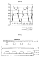
- FIG. 2e compares light intensity after irradiating light from under a bottom surface wherein a protrusion with a height of 2 ⁇ m or 8 ⁇ m is formed;
- FIG. 3a illustrates irradiation of light from above a bottom surface of a microchannel wherein a protrusion is formed according to the present disclosure
- FIG. 3b shows a photographic image obtained after irradiating light from above the bottom surface of the microchannel as in FIG. 3a ;
- FIGS. 3c and 3d respectively show a photographic image obtained after irradiating light from above a bottom surface wherein a protrusion with a height of 2 ⁇ m and 8 ⁇ m is formed;
- FIG. 3e compares light intensity after irradiating light from under or from above a bottom surface wherein a protrusion is formed
- FIGS. 3f-3i compare fluorescence intensity after irradiating light from under or from above a bottom surface of a microfluidic device wherein a protrusion with a height of 8 ⁇ m is formed at different sample concentrations;
- FIG. 4a shows a cross-sectional view of a conical protrusion
- FIG. 4b is a photographic image of a bottom surface wherein a conical protrusion is formed
- FIG. 5a shows a cross-sectional view of a hemispherical protrusion
- FIG. 5b is a photographic image of a bottom surface wherein a hemispherical protrusion is formed
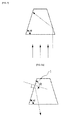
- FIG. 6 is a figure for illustrating a critical angle at the interface of different media
- FIG. 7 shows incidence of light from a bottom surface of a protrusion with a wall having a tilt angle of ⁇
- FIGS. 8a and 8b show light paths for protrusions having different tilt angles
- FIGS. 9a-9e show light-harvesting effect at varying tilt angles
- FIG. 10 shows photographic images showing experimental result for protrusions having different cross sections.
- FIG. 11 shows an analysis device for irradiating light from under a microfluidic device according to the present disclosure in order to analyze a sample using the microfluidic device.
- FIG. 2a schematically shows a cross section of a microchannel 50 wherein a protrusion is formed according to the present disclosure and irradiation of light from under a bottom surface of the microchannel 50.
- the microchannel 50 is formed in a space between an upper substrate 40 and a lower substrate 10.
- a protrusion 20 is formed on a bottom surface of the microchannel 50, i.e. on the lower substrate 10.
- the protrusion 20 has a truncated conical shape.
- a primary capture antibody is uniformly coated on the bottom surface of the microchannel 50 and a sample such as blood is made to flow through the microchannel. Then, an antigen included in the sample binds with the capture antibody. The antigen captured by the antibody is reacted again with a fluorescence-labeled secondary antibody to bind the antigen with the secondary antibody.
- the protrusion 20 serves to increase the surface area of the antigen-antibody reaction.
- the substance resulting from the binding of the primary capture antibody, the antigen and the secondary antibody exhibits fluorescence due to the fluorescent substance labeled at the secondary antibody. Accordingly, by detecting the fluorescence emitted from the secondary antibody, the antigen included in the sample may be analyzed quantitatively and qualitatively.
- FIG. 2b shows a photographic image obtained after irradiating light from under the bottom surface of the microchannel.
- the fluorescent substance located at the side wall of the conical protrusion 20 exhibits fluorescence of very high intensity. It is because the tilted side wall of the protrusion 20 provides a light-harvesting effect. Accordingly, it is easier to optically detect the fluorescent substance. The light-harvesting effect will be described in detail later.
- FIGS. 2c and 2d respectively show a photographic image obtained after irradiating light from under a bottom surface wherein a protrusion with a height of 2 ⁇ m and 8 ⁇ m is formed.
- the fluorescence intensity is higher when the protrusion when the height of the protrusion is 8 ⁇ m ( FIG. 2d ).
- the experimental result reveals that improved light intensity is achieved when the height of the protrusion is from 2 ⁇ m to 20 ⁇ m.
- FIG. 2e compares fluorescence intensity (dimensionless) after irradiating light from under a bottom surface wherein a protrusion with a height of 2 ⁇ m or 8 ⁇ m is formed.
- the abscissa is a relative distance from an arbitrary reference point.
- FIG. 3a illustrates irradiation of light from above the bottom surface of the microchannel 50 wherein the protrusion is formed according to the present disclosure.
- FIGS. 3c and 3d respectively show a photographic image obtained after irradiating light from above a bottom surface wherein a protrusion with a height of 2 ⁇ m and 8 ⁇ m is formed.
- it is difficult to optically detect the fluorescent substance since the intensity of the fluorescent light emitted from the fluorescent substance is very weak, in both cases where the height of the protrusion is 2 ⁇ m and 8 ⁇ m. It is because the light-harvesting effect by the protrusion is not achieved when the light is irradiated light from above the bottom surface of the microchannel wherein the protrusion is formed.
- FIG. 3e compares fluorescence intensity after irradiating light from under or from above a bottom surface wherein a protrusion with a height of 8 ⁇ m is formed. As seen from FIG. 3e , a strong light intensity is observed when the light is irradiated light from under the bottom surface of the microchannel wherein the protrusion is formed.
- FIGS. 3f-3i compare fluorescence intensity after irradiating light from under or from above a bottom surface of a microfluidic device wherein a protrusion with a height of 8 ⁇ m is formed at different sample concentrations.
- FIGS. 3f-3i show a result of performing experiments using the Frend microfluidic device (NanoEnTek, Korea) by the sandwich method, using Tnl as an analyte. After injecting a sample to the microfluidic device holding a primary capture antibody, the antigen-antibody reaction was measured according to the sandwich method by measuring the intensity of fluorescence signal using an optical instrument.
- the abscissa is a relative distance from an arbitrary reference point and the ordinate is fluorescence intensity (dimensionless).
- the samples contained the analyte (Tnl) at concentrations of 24 ng/mL, 12 ng/mL and 6 ng/mL for FIG. 3f , FIG. 3g and FIG. 3h , respectively.
- the light intensity is higher when the light is irradiated from under the bottom surface of the microchannel wherein the protrusion is formed than when the light is irradiated from above the bottom surface.
- the light intensity is improved by about 21% when the light is irradiated from under the bottom surface as compared to when the light is irradiated from above.
- the light intensity is improved by approximately 22%, and in FIG. 3h , by about 20%. Accordingly, the light intensity is improved by about 21% on average when the light is irradiated from under the bottom surface than when the light is irradiated from above.
- FIG. 4a shows a cross-sectional view of a truncated conical protrusion formed on a bottom surface of a microchannel according to an exemplary embodiment of the present disclosure.
- the diameter of the lower base of the truncated cone may be 4-80 ⁇ m.
- the aspect ratio (i.e., a:c) of the truncated cone may be about 2:1 to 4:1.
- the tilt angle ⁇ of the side wall of the truncated cone may be about 50-80°.
- the diameter b of the upper base may be determined to satisfy the above requirements.
- the upper base of the truncated cone may be either planar or convex.
- the height c of the protrusion may be 2-200 ⁇ m, specifically 2-190 ⁇ m, more specifically 5-20 ⁇ m.
- the height of the microchannel 50 ( FIG. 2a ) may be at least 5 ⁇ m, specifically 10-200 ⁇ m.
- the protrusion may be formed on a lower substrate 10 ( FIG. 2a ) which becomes the bottom surface of the microchannel by a microelectromechanical system (MEMS) process based on the semiconductor process, a microfabrication technique or a molding technique.
- MEMS microelectromechanical system
- FIG. 4b is a scanning electron microscopic (SEM) image of a bottom surface of a microchannel wherein truncated conical protrusions as shown in FIG. 4a are formed in lattice form.
- the diameter of the lower base of the truncated cone is 25 ⁇ m and its height is 8 ⁇ m.
- FIG. 5a shows a cross-sectional view of a hemispherical protrusion formed on a bottom surface of a microchannel according to another exemplary embodiment of the present disclosure.
- the diameter of the lower base of the hemisphere may be 10-50 ⁇ m.
- the aspect ratio (i.e., a:c) of the hemisphere may be about 2:1 to 4:1.
- the tilt angle ⁇ of the side wall of the hemisphere may be about 50°-80°.
- FIG. 5b is an SEM image of a bottom surface wherein hemispherical protrusions as shown in FIG. 5a are formed in lattice form.
- the diameter of the lower base of the hemisphere is 25 ⁇ m and its height is 8 ⁇ m.
- the critical angle ⁇ c is about 67°.
- the critical angle ⁇ c is about 67°.
- FIG. 7 shows incidence of light from a bottom surface of a protrusion with a wall having a tilt angle of ⁇ .
- the tilt angle ⁇ is larger than the critical angle ⁇ c , the light incident from under the bottom surface of the protrusion is totally reflected internally at the side wall and travels to the opposing side wall of the protrusion. As a result, it is easier to excite the fluorescent particle fixed on the side wall of the protrusion.
- FIGS. 8a and 8b show paths of light emitted from a fluorescent particle 1 for protrusions having different tilt angles ⁇ .
- the light emitted from the fluorescent particle 1 is incident on the side wall of the protrusion with an angle of incidence ⁇ larger than the critical angle ⁇ c and is totally reflected internally toward the bottom surface of the protrusion.
- the tilt angle ⁇ of the protrusion is larger than the critical angle, the light incident on the protrusion is totally reflected internally and the light-harvesting effect of light is increased.
- the tilt angle ⁇ is too small as in FIG. 8b , it is difficult to harvest the light since it is scattered.
- FIGS. 9a-9e show light-harvesting effect at varying tilt angles. As seen from the figures, when the tilt angle is 50° or larger, specifically 50-80°, the light emitted from the fluorescent particle 1 is totally reflected internally toward the bottom surface of the protrusion.
- biochemical samples e.g., blood, body fluid, urine, etc.
- other samples used in experiments tend to be dispersions or solutions with water as dispersion medium or solvent.
- refractive indices of various media and their critical angles for water are described in Table 1.
- the present disclosure is also applicable, for example, to organic solutions having, e.g., alcohol as solvent. Therefore, according to the present disclosure, the critical angle may be calculated considering the refractive index of the particular biochemical sample, aqueous dispersion, aqueous solution, organic solution, etc. to be tested to design the protrusion of the microchannel.
- experiment may be performed with the reaction product (e.g., antigen fixed in the channel as a result of antigen-antibody reaction).
- the critical angle may be calculated considering the refractive index of the protrusion and that of air to design the protrusion of the microchannel.
- FIG. 10 shows photographic images showing experimental result for protrusions having different cross sections.
- the fluorescence intensity is strongest when the cross section of the protrusion is clover-shaped, followed by circular.
- the fluorescence intensity is weakest for the hexagonal cross section. It is because the light-harvesting area increases as the circumference of the cross section of the protrusion is larger.
- the cross section of the protrusion has a concave portion such as the clover shape, the light-harvesting effect is improved further since reflected light is superimposed there.
Landscapes
- Health & Medical Sciences (AREA)
- Chemical & Material Sciences (AREA)
- Life Sciences & Earth Sciences (AREA)
- Analytical Chemistry (AREA)
- General Health & Medical Sciences (AREA)
- Immunology (AREA)
- Physics & Mathematics (AREA)
- Biochemistry (AREA)
- General Physics & Mathematics (AREA)
- Pathology (AREA)
- Hematology (AREA)
- Engineering & Computer Science (AREA)
- Clinical Laboratory Science (AREA)
- Molecular Biology (AREA)
- Dispersion Chemistry (AREA)
- Biomedical Technology (AREA)
- Chemical Kinetics & Catalysis (AREA)
- Urology & Nephrology (AREA)
- Biotechnology (AREA)
- Microbiology (AREA)
- Cell Biology (AREA)
- Food Science & Technology (AREA)
- Medicinal Chemistry (AREA)
- Optical Measuring Cells (AREA)
- Investigating, Analyzing Materials By Fluorescence Or Luminescence (AREA)
- Automatic Analysis And Handling Materials Therefor (AREA)
Applications Claiming Priority (2)
| Application Number | Priority Date | Filing Date | Title |
|---|---|---|---|
| KR1020090123007A KR101142793B1 (ko) | 2009-12-11 | 2009-12-11 | 저면에 돌출물이 형성된 미세채널을 구비하는 미세유체 장치 |
| PCT/KR2010/008448 WO2011071262A2 (fr) | 2009-12-11 | 2010-11-26 | Dispositif microfluidique comprenant un microconduit présentant des saillies formées sur sa surface de fond |
Publications (1)
| Publication Number | Publication Date |
|---|---|
| EP2544009A2 true EP2544009A2 (fr) | 2013-01-09 |
Family
ID=44146017
Family Applications (1)
| Application Number | Title | Priority Date | Filing Date |
|---|---|---|---|
| EP10836158A Withdrawn EP2544009A2 (fr) | 2009-12-11 | 2010-11-26 | Dispositif microfluidique comprenant un microconduit présentant des saillies formées sur sa surface de fond |
Country Status (5)
| Country | Link |
|---|---|
| US (1) | US20120282625A1 (fr) |
| EP (1) | EP2544009A2 (fr) |
| JP (1) | JP2013513795A (fr) |
| KR (1) | KR101142793B1 (fr) |
| WO (1) | WO2011071262A2 (fr) |
Families Citing this family (1)
| Publication number | Priority date | Publication date | Assignee | Title |
|---|---|---|---|---|
| KR101306338B1 (ko) * | 2011-11-09 | 2013-09-06 | 삼성전자주식회사 | 미세유동장치 및 이를 포함하는 미세유동시스템 |
Family Cites Families (7)
| Publication number | Priority date | Publication date | Assignee | Title |
|---|---|---|---|---|
| AU642444B2 (en) * | 1989-11-30 | 1993-10-21 | Mochida Pharmaceutical Co., Ltd. | Reaction vessel |
| US6454924B2 (en) * | 2000-02-23 | 2002-09-24 | Zyomyx, Inc. | Microfluidic devices and methods |
| JP4897192B2 (ja) * | 2002-10-30 | 2012-03-14 | 株式会社日立製作所 | 柱状微小突起群を備えた機能性基板とその製造方法 |
| JP2005118634A (ja) * | 2003-10-14 | 2005-05-12 | Japan Science & Technology Agency | マイクロミキシングデバイス |
| KR100868769B1 (ko) | 2007-06-07 | 2008-11-17 | 삼성전자주식회사 | 미세유체 칩 및 이의 제조방법 |
| KR101435521B1 (ko) * | 2008-01-23 | 2014-08-29 | 삼성전자 주식회사 | 바이오칩 |
| KR100931983B1 (ko) | 2008-04-04 | 2009-12-15 | 한국과학기술원 | 미세유체 혼합 장치 |
-
2009
- 2009-12-11 KR KR1020090123007A patent/KR101142793B1/ko not_active Expired - Fee Related
-
2010
- 2010-11-26 WO PCT/KR2010/008448 patent/WO2011071262A2/fr not_active Ceased
- 2010-11-26 US US13/512,319 patent/US20120282625A1/en not_active Abandoned
- 2010-11-26 EP EP10836158A patent/EP2544009A2/fr not_active Withdrawn
- 2010-11-26 JP JP2012543013A patent/JP2013513795A/ja active Pending
Non-Patent Citations (1)
| Title |
|---|
| See references of WO2011071262A2 * |
Also Published As
| Publication number | Publication date |
|---|---|
| KR101142793B1 (ko) | 2012-05-08 |
| US20120282625A1 (en) | 2012-11-08 |
| WO2011071262A3 (fr) | 2011-11-03 |
| KR20110066381A (ko) | 2011-06-17 |
| WO2011071262A2 (fr) | 2011-06-16 |
| JP2013513795A (ja) | 2013-04-22 |
Similar Documents
| Publication | Publication Date | Title |
|---|---|---|
| JP7129909B2 (ja) | 流体試料中の粒子を特徴付けるためのシステム及び方法 | |
| US7952705B2 (en) | Integrated microfluidic optical device for sub-micro liter liquid sample microspectroscopy | |
| EP2391451B1 (fr) | Structures pour le contrôle des interactions de la lumière avec des dispositifs microfluidiques | |
| KR102113377B1 (ko) | 격리 펜을 갖는 미세유체 소자 및 이를 사용한 생물학적 미세 물체를 시험하는 방법 | |
| JP5129347B2 (ja) | 液体試料中の粒子を分析するための方法及び装置 | |
| ES2913335T3 (es) | Análisis de imagen y medición de muestras biológicas | |
| CN103547925B (zh) | 用于分子或粒子的超灵敏探测的系统、装置以及方法 | |
| US20080038738A1 (en) | Detecting tumor biomarker in oral cancer | |
| US20100291588A1 (en) | Systems and methods including self-contained cartridges with detection systems and fluid delivery systems | |
| JP7207294B2 (ja) | 解析デバイス、解析キット、及び解析システム | |
| JP2020510189A (ja) | 異なる間隔の高さを使用するアッセイ法 | |
| CA2829178C (fr) | Quantification rapide de biomolecules dans un biocapteur nanofluidique selectivement fonctionnalise et procede associe | |
| WO2011034678A1 (fr) | Utilisation de surfaces superhydrophobes dans des dosages d'agglutination de liquides | |
| US20190225930A1 (en) | Microfluidic filter devices and methods | |
| US12456315B2 (en) | Methods for distinguishing particles in a fluid sample | |
| WO2009029177A1 (fr) | Dispositif optique microfluidique intégré pour la microspectroscopie d'échantillons liquides d'un volume inférieur au microlitre | |
| US20150177118A1 (en) | Fluidic optical cartridge | |
| CA2547109A1 (fr) | Cuve de reaction jetable a elements optiques integres | |
| JP5125680B2 (ja) | 分離チップおよび分離方法 | |
| EP2544009A2 (fr) | Dispositif microfluidique comprenant un microconduit présentant des saillies formées sur sa surface de fond | |
| KR20170104817A (ko) | 단일세포 검출 및 채집용 슬라이드 | |
| HK1163591A (en) | Structures for controlling light interaction with microfluidic devices | |
| HK1163591B (en) | Structures for controlling light interaction with microfluidic devices |
Legal Events
| Date | Code | Title | Description |
|---|---|---|---|
| PUAI | Public reference made under article 153(3) epc to a published international application that has entered the european phase |
Free format text: ORIGINAL CODE: 0009012 |
|
| 17P | Request for examination filed |
Effective date: 20120709 |
|
| AK | Designated contracting states |
Kind code of ref document: A2 Designated state(s): AL AT BE BG CH CY CZ DE DK EE ES FI FR GB GR HR HU IE IS IT LI LT LU LV MC MK MT NL NO PL PT RO RS SE SI SK SM TR |
|
| DAX | Request for extension of the european patent (deleted) | ||
| STAA | Information on the status of an ep patent application or granted ep patent |
Free format text: STATUS: THE APPLICATION IS DEEMED TO BE WITHDRAWN |
|
| 18D | Application deemed to be withdrawn |
Effective date: 20140603 |