EP2544079A1 - Tragbares endgerät - Google Patents
Tragbares endgerät Download PDFInfo
- Publication number
- EP2544079A1 EP2544079A1 EP11750759A EP11750759A EP2544079A1 EP 2544079 A1 EP2544079 A1 EP 2544079A1 EP 11750759 A EP11750759 A EP 11750759A EP 11750759 A EP11750759 A EP 11750759A EP 2544079 A1 EP2544079 A1 EP 2544079A1
- Authority
- EP
- European Patent Office
- Prior art keywords
- capacitance
- distance
- touch panel
- finger
- counter electrode
- Prior art date
- Legal status (The legal status is an assumption and is not a legal conclusion. Google has not performed a legal analysis and makes no representation as to the accuracy of the status listed.)
- Withdrawn
Links
Images






Classifications
-
- G—PHYSICS
- G06—COMPUTING OR CALCULATING; COUNTING
- G06F—ELECTRIC DIGITAL DATA PROCESSING
- G06F3/00—Input arrangements for transferring data to be processed into a form capable of being handled by the computer; Output arrangements for transferring data from processing unit to output unit, e.g. interface arrangements
- G06F3/01—Input arrangements or combined input and output arrangements for interaction between user and computer
- G06F3/03—Arrangements for converting the position or the displacement of a member into a coded form
- G06F3/041—Digitisers, e.g. for touch screens or touch pads, characterised by the transducing means
- G06F3/044—Digitisers, e.g. for touch screens or touch pads, characterised by the transducing means by capacitive means
-
- G—PHYSICS
- G06—COMPUTING OR CALCULATING; COUNTING
- G06F—ELECTRIC DIGITAL DATA PROCESSING
- G06F3/00—Input arrangements for transferring data to be processed into a form capable of being handled by the computer; Output arrangements for transferring data from processing unit to output unit, e.g. interface arrangements
- G06F3/01—Input arrangements or combined input and output arrangements for interaction between user and computer
- G06F3/048—Interaction techniques based on graphical user interfaces [GUI]
- G06F3/0481—Interaction techniques based on graphical user interfaces [GUI] based on specific properties of the displayed interaction object or a metaphor-based environment, e.g. interaction with desktop elements like windows or icons, or assisted by a cursor's changing behaviour or appearance
- G06F3/04817—Interaction techniques based on graphical user interfaces [GUI] based on specific properties of the displayed interaction object or a metaphor-based environment, e.g. interaction with desktop elements like windows or icons, or assisted by a cursor's changing behaviour or appearance using icons
-
- G—PHYSICS
- G06—COMPUTING OR CALCULATING; COUNTING
- G06F—ELECTRIC DIGITAL DATA PROCESSING
- G06F3/00—Input arrangements for transferring data to be processed into a form capable of being handled by the computer; Output arrangements for transferring data from processing unit to output unit, e.g. interface arrangements
- G06F3/01—Input arrangements or combined input and output arrangements for interaction between user and computer
- G06F3/048—Interaction techniques based on graphical user interfaces [GUI]
- G06F3/0487—Interaction techniques based on graphical user interfaces [GUI] using specific features provided by the input device, e.g. functions controlled by the rotation of a mouse with dual sensing arrangements, or of the nature of the input device, e.g. tap gestures based on pressure sensed by a digitiser
- G06F3/0488—Interaction techniques based on graphical user interfaces [GUI] using specific features provided by the input device, e.g. functions controlled by the rotation of a mouse with dual sensing arrangements, or of the nature of the input device, e.g. tap gestures based on pressure sensed by a digitiser using a touch-screen or digitiser, e.g. input of commands through traced gestures
-
- G—PHYSICS
- G06—COMPUTING OR CALCULATING; COUNTING
- G06F—ELECTRIC DIGITAL DATA PROCESSING
- G06F2203/00—Indexing scheme relating to G06F3/00 - G06F3/048
- G06F2203/041—Indexing scheme relating to G06F3/041 - G06F3/045
- G06F2203/04101—2.5D-digitiser, i.e. digitiser detecting the X/Y position of the input means, finger or stylus, also when it does not touch, but is proximate to the digitiser's interaction surface and also measures the distance of the input means within a short range in the Z direction, possibly with a separate measurement setup
-
- H—ELECTRICITY
- H04—ELECTRIC COMMUNICATION TECHNIQUE
- H04M—TELEPHONIC COMMUNICATION
- H04M2250/00—Details of telephonic subscriber devices
- H04M2250/12—Details of telephonic subscriber devices including a sensor for measuring a physical value, e.g. temperature or motion
-
- H—ELECTRICITY
- H04—ELECTRIC COMMUNICATION TECHNIQUE
- H04M—TELEPHONIC COMMUNICATION
- H04M2250/00—Details of telephonic subscriber devices
- H04M2250/22—Details of telephonic subscriber devices including a touch pad, a touch sensor or a touch detector
Definitions
- the present invention is related to a mobile terminal which is provided with a touch panel.
- a mobile terminal which is a portable type computer has been developed.
- This mobile terminal displays a plurality of icons, which can be selected by a user, on a display section.
- the user operates an operation section to select a desired icon from among the plurality of icons displayed on the display section.
- the mobile terminal displays the contents of the selected icon on the display section.
- the mobile terminal for which a touch panel of a capacitance type is provided instead of the display section has been developed.
- the user can select a desired icon from among a plurality of icons by touching the touch panel with a finger. Because the mobile terminal has been miniaturized, the size of the touch panel which is provided for the mobile terminal is restrained. On the other hand, if the icons to be displayed once on the touch panel increase more, the user can select the desired icon the less number of times.
- the touch panel of the capacitance type when the touch panel of the capacitance type is provided for the mobile terminal, a plurality of transparent electrodes of linear sensors and so on are arranged on the touch panel in the pitch of about 5mm.
- the mobile terminal detects the capacitance values of the capacitances formed between the plurality of transparent electrodes and the finger when the finger touches the touch panel, and estimates the position of the finger. Therefore, it is difficult to specify the position of the finger on the touch panel and it is easy to cause an error. Thus, it is different from a method of selecting a position with a mouse, a stylus pen and so on.
- a range of the icons on the panel which the can be selected through the touch is a part or its periphery of the displayed icon in many cases. When the displayed icon is small, it is difficult for the user to right select the icon.
- the touch panel of the capacitance type is provided for the mobile terminal, it is general that the touch panel is touched with not a stylus pen but the finger. If the displayed icon is small, when the user tries to touch the touch panel, the desired icon can be concealed with the other fingers so that the desired icon can not be confirmed.
- JAP 2009-66612A a technique which an object icon is displayed in an expanded state is described in JAP 2009-66612A .
- this technique there is no detailed description of the position of an operation instructing section and a distance between a touch panel and of the operation instructing section.
- the object icon of the plurality of icons which is displayed on the touch panel is displayed in an expansion state based on a capacitance value between the operation instructing section and the touch panel. Because the object icon is displayed in the expansion state when the operation instructing section approaches the touch panel, the improvement of operability can be attempted to the user and the user can handle it easily.
- the operation instructing section may be a touch pen (a stylus pen) in addition to the finger. Therefore, when an object which is not the finger and the touch pen (such as a needle, a sharp pen, a ball-point pen, ...) approaches the touch panel, the object icon of the plurality of icons displayed on the touch panel is displayed in an expansion state based on the capacitance value between the object and the touch panel. In this case, there is a case that the icon which is not the object is displayed in the expansion state, and the operability is improved to the user.
- a touch pen a stylus pen
- JP 2006-236143A a distance between a finger of a user and a touch panel is determined from an image showing a main display section (the touch panel) and its neighborhood and taken by a camera. When the distance is a predetermined distance, an icon is displayed on the touch panel in the expansion state.
- this technique needs the space where the camera is arranged.
- JP H08-212005A and JP H11-065769A another technique is described in JP H08-212005A and JP H11-065769A , in which a distance detection mechanism emitting light is arranged around the touch panel. For example, when the light is interrupted at a position near the touch panel after light is interrupted at a position far from the touch panel, an icon is displayed on the touch panel in an expansion state. However, in this technique, because the distance detection mechanism is arranged around the touch panel, the depth would be provided to the touch panel.
- JP 2007-004660A and JP H05-046308 a another technique is described in JP 2007-004660A and JP H05-046308 a, in which an icon and a key are displayed in the expansion state in a size according to the size of a finger when the finger touches a touch panel.
- the present invention provides a mobile terminal in which a malfunction is prevents and the improvement of operability can be attempted.
- a mobile terminal of the present invention is provided with a touch panel of a capacitance type, a display control section, a capacitance measuring section, a distance determining section, a distribution data generating section and a storage section.
- a plurality of transparent electrodes are arranged in the touch panel to show coordinates.
- the display control section displays a plurality of icons which can be selected by a user, on the touch panel.
- the capacitance measuring section periodically measures a capacitance value of each of a plurality of capacitances which are formed between the plurality of transparent electrodes and a finger of the user as a counter electrode.
- the coordinate determining section determines an estimation coordinate showing an estimation position of the finger based on the capacitance values and the coordinates corresponding to the plurality of transparent electrodes.
- the distance determining section calculates an estimation distance showing a distance between the touch panel and the finger based on a selection capacitance value, which has the maximum capacitance value, of the capacitance values.
- the distribution data generating section generates data showing a distribution of the measured capacitance values as capacitance distribution data.
- the storage section stores set capacitance distribution data showing a distribution of a plurality of capacitance values set every distance between the finger position and the touch panel.
- the display control section displays the plurality of icons in a basic size when data similar to the capacitance distribution data does not exist in the set capacitance distribution data stored in the storage section.
- the display control section select as a candidate icon, one which is arranged in the estimation coordinate, of the plurality of icons displayed on the touch panel and controls the touch panel to display the selection icon in a selection size which is larger than the basic size, when the data similar to the capacitance distribution data exists in the set capacitance distribution data stored in the storage section.
- the icon is displayed on the touch panel in the expansion state when detecting that the finger of the user is approaching the touch panel, the malfunction can be prevented and the improvement of operability can be attempted to the user.
- FIG. 1 is a block diagram showing a configuration of a mobile terminal according to a first exemplary embodiment of the present invention.
- the mobile terminal according to the first exemplary embodiment of the present invention is a portable type computer and is provided with a touch panel 1 of a capacitance type, a control section 2, a storage section 3 and an operation section 4.
- the touch panel 1 is an input/output unit from which data can be inputted by touching a screen while displaying letters, diagrams and so on, and displays a plurality of icons which are selectable by a user.
- the control section 2 takes various data therein from the storage section 3 by and stores a processed result in the storage section 3.
- control section 2 a CPU (Central Processing Unit) is exemplified and as the storage section 3, a memory such as a storage medium is exemplified.
- a computer program executed by a computer is stored in the storage section 3.
- the control section 2 reads the computer program from the storage section 3 to execute it.
- the control section 2 is provided with a display control section 21 which controls the touch panel 1 to display a plurality of icons which can be selected by the user on the touch panel 1 in a basic size.
- the display control section 21 controls the touch panel 1 to display the contents of a desired icon among the plurality of icons which are displayed on the touch panel 1 in response to an operation of the operation section 4 by the user.
- the user can operate the operation section 4 which contains necessary and minimum keys.
- the necessary and minimum keys contain a power supply key 41 to supply power to the mobile terminal.
- the mobile terminal can select the desired icon from among the plurality of icons by the user touching the touch panel 1 with the finger.
- the control section 2 is further provided with a capacitance measuring section 22, a coordinate determining section 23, a distance determining section 24, and a distribution data generating section 25. These operations will be described later.
- the storage section 3 is provided with a distance determination table 31 and a size determination table 32. The contents which are stored in these tables will be described later.
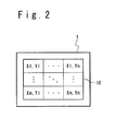
- FIG. 2 shows a part of the configuration of the touch panel 1.
- a plurality of transparent electrodes 18 are arranged in m rows and columns on the touch panel 1 (m and n are integers equal to or more than 2).
- the plurality of transparent electrodes 10 show coordinates (X1,Y1) to (Xm, Yn) according to the arrangement positions.
- the capacitance measuring section 22 measures capacitance values C(X1, Y1) to C(Xm, Yn) of a plurality of capacitances formed between the plurality of transparent electrodes 10 (X1, Y1) to (Xm, Yn) and a counter electrode.
- An object other than a finger e.g. a touch pen, a needle, a sharp pen, a ball-point pen, .etc. can function as the counter electrode.
- the capacitance values C(X1, Y1) to C(Xm, Yn) of the capacitances to be formed are different even if they are compared at a same position (coordinate) and in a same distance. That is, a distribution of plurality of capacitance values C(X1, Y1) to C(Xm, Yn) is different.
- set capacitance distribution data 33 is set to show the distribution of capacitance values C(X1, Y1) to C(Xm, Yn) for every finger position (coordinate) and every distance between the touch panel 1 and the finger and is stored in the storage section 3 in advance. It is desirable that that the distribution patterns to be set are plural. Thus, only when the object being approaching the touch panel 1 is the finger of the user, the icon which is displayed on the touch panel 1 can be displayed to be expanded. This operation will be described in detail.
- FIG. 7 is a flow chart showing the operation of the mobile terminal according to the first exemplary embodiment of the present invention.
- a process of displaying the icons in the mobile terminal is started periodically.
- the mobile terminal executes a display process (step S17) repeatedly.
- the capacitance measuring section 22 is started to measure the capacitance values C(X1, Y1) to C(Xm, Yn), and the distribution data generating section 25 generates capacitance distribution data 60 (Step S11).
- the coordinate determining section 23 determines an estimation coordinate (X, Y) showing an estimated position of the finger based on the capacitance distribution data 6C (Step S12).
- the distance determining section 24 determines an estimation distance Dxy showing a distance between the touch panel 1 and the finger based on the capacitance distribution data 60 (Step S13).
- Step S14-YES When determining that the finger has touched the touch panel 1 (Step S14-YES), the display control section 21 executes a process after the selection under assumption of the selection of one icon. When determining (step S14-NO) that the finger has not touch the touch panel 1, the display control section 21 executes a usual displaying process or an expansion/reduction displaying process.
- the display control section 21 determines whether or not a change of the icon size is required. When determining (step S15-NO) that it does not need the size change, the displaying process is executed without changing the size (Step S17). When determining that the size change is necessary (Step S15-YES), the display control section 21 selects the icon size (step S16) and executes the displaying process (Step S17).
- the display control section 21 controls the touch panel 1 to display the plurality of icons 50 selectable by the user on the touch panel 1 in the basic size (Step S10-NO, Step S17).
- the capacitance measuring section 22 executes a measuring process periodically. Therefore, for every period T (Step S10-YES), the capacitance measuring section 22 executes the measuring process, that is, measures the capacitance values C(X1, Y1) to C(Xm, Yn) of the capacitances formed between the plurality of transparent electrodes 10 (X1, Y1) to (Xm, Yn) and the counter electrode which is the finger of the user (Step S11).
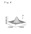
- the distribution data generating section 25 When the measurement ends, the distribution data generating section 25 generates the capacitance distribution data 60 to show a distribution of the measured capacitance values C(X1, Y1) to C(Xm, Yn), as shown in FIG. 4 .
- the distribution data generating section 25 stores the capacitance distribution data 60 in the storage section 3 temporarily (only for one period).
- the coordinate determining section 23 determines the estimation coordinate (X, Y) showing the estimated position of the finger based on the coordinates (X1, Y1) to (Xm, Yn) shown by the plurality of transparent electrodes 10 and the capacitance values C(X1, Y1) to C(Xm, Yn) (Step S12).
- the capacitance values in the coordinates (X1, Y1) to (Xm, Yn) shown by the plurality of transparent electrodes 10 are C(X1, Y1) to C(Xm, Yn), and the estimation coordinate (X, Y) is calculated from the following equations (1) and (2) :
- the distance determining section 24 determines the estimation distance Dxy showing the distance between the touch panel 1 and the finger based on a selection capacitance value C(X, Y) which has the highest capacitance value among the capacitance values C(X1, Y1) to C(Xm, Yn) (Step S13).
- FIG. 5 shows the contents which are stored in the distance determination table 31 in a graph.
- the capacitance values in range from 0[F] to the maximum set capacitance value and the distances in a range from the maximum set distance to 0[mm] are related and are stored.
- a distance, which is longer than C[mm] and shorter than the maximum set distance, of the distances shown by the distance determination table 31 is defined as a first set distance DS1 and the shortest distance which is 0[mm] is defined as a second set distance DS2.
- the capacitance value, corresponding to the first set distance DS1, of the capacitance values shown by the distance determination table 31 is defined as first capacitance value Cs1, and a maximum set capacitance value is defined as a second capacitance value Cs2.
- the selection capacitance value C(X, Y) meets Cs1sC(X, Y) ⁇ Cs2.
- a distance immediately before the finger touches the touch panel 1 is defined as DS3 and a capacitance value at that time is defined as Cs3.
- the distance determining section 24 determines the distance corresponding to the selection capacitance value C(X, Y) from the distances shown by the distance determination table 31 as the estimation distance Dxy.
- the display control section 21 executes a usual displaying process or an expansion/reduction displaying process when the finger is not in a touch condition with the touch panel 1 (step S14-NO).
- the display control section 21 executes the usual displacing process.
- the display control section 21 controls the touch panel to display a plurality of icons 50 on the touch panel 1 in the basic size (Steps S16, S17). That is, the plurality of icons 50 remains displayed on the touch panel 1 in the basic size.
- the data showing the distribution similar to the capacitance distribution data 60 exists in the set capacitance distribution data 33 which is stored in the storage section 3 (Step S15-YES), and when the estimation distance Dxy is equal to or less than the first set distance DS, the display control section 21 executes the expansion/reduction displaying process.
- the display control section 21 selects the icon 50 as an object icon 51, which is displayed near the estimation coordinate (X, Y), from the plurality of icons 50 which are displayed on the touch panel 1, and displays the object icon 51 on the touch panel 1 in a selected size Axy (Steps S16, S17).
- the selected size Axy is a size which is in inverse proportion to the estimation distance Dxy. As shown in FIG. 3B , the selected size Axy in this case is equal to or larger than the basic size.
- FIG. 6 shows the contents stored in the size determination table 32 in a graph.
- FIG. 6 shows this graph.
- the display control section 21 refers to the size determination table 32 to select the first size A1 as the selected size Axy (Step S16), and controls the touch panel 1 to display the plurality of icons 50 on the touch panel 1 in the first size A1 (Step S17).
- the display control section 21 selects the icon 50 as an object icon 51, which is displayed near the estimation coordinate (X, Y), from the plurality of icons 50 which are displayed on the touch panel 1.
- the display control section 21 refers to the size determination table 32 to select the size corresponding to the estimation distance Dxy as the selected size Axy (Step S16), and controls the touch panel 1 to display the object icon 51 on the touch panel 1 in the selected size Axy (Step S17).
- the display control section 21 controls the touch panel 1 to display the contents of the object icon 51 on the touch panel 1 without executing the usual displaying process and the expansion/reduction displaying process (Step S14-YES).
- the estimation coordinate (X, Y) showing the estimated position of the finger and the estimation distance Dxy showing a distance between the finger and the touch panel 1 are determined based on the capacitance value between the finger and the touch panel 1, and the capacitance distribution data 60 is generated to show a distribution of capacitance values.
- the object icon 51 which is displayed near the estimation coordinate (X, Y), of the plurality of icons 50 which are displayed on the touch panel 1 is displayed on the touch panel 1 in a size larger than the basic size (first size A1), and in the size which is in inverse proportion to the estimation distance Dxy. That is, when the distance between the finger and the touch panel 1 is longer than the first set distance DS1, the object icon 51 is displayed in the reference size. When the distance between the finger and the touch panel 1 is equal to or less than the first set distance DS1, the object icon 51 is displayed in a size which is larger than the basic size.
- the mobile terminal when it is detected that the finger of the user is approaching the touch panel 1, an icon is displayed on the touch panel 1 to be expanded. Therefore, a malfunction can be prevented and the improvement of the operability can be attained to the user.
- FIG. 8 is a block diagram showing the configuration of the mobile terminal according to a second exemplary embodiment of the present invention.
- the description of the same portion as that of the first exemplary embodiment is omitted.
- the operation section 4 of the mobile terminal contains the power supply key 41 and a specific key 42 as the necessary and minimum keys.
- the specific key 42 is added.
- the processing of the mobile terminal is substantially the same as in the first implementation, but is different in that the capacitance measuring section 22 executes a measuring process at step S11 when the user operates the specific key 42.
- the capacitance measuring section 22 executes the measuring process.
- an icon is displayed in the expansion state only when the user operates the specific key 42, a malfunction can be prevented.
- the mobile terminal according to the second exemplary embodiment of the present invention can attempt a low power consumption amount, compared with the mobile terminal according to the first exemplary embodiment.
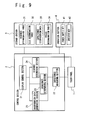
- FIG. 9 is a block diagram showing the configuration of the mobile terminal according to a third exemplary embodiment of the present invention.
- the description of the same portion as those of the first and second exemplary embodiments is omitted.
- the storage section 3 of the mobile terminal according to the third exemplary embodiment is provided with a period determination table 34.
- the period determination table 34 is used when the period to measure a capacitance value is to be determined.
- FIG. 10 shows the contents stored in the period determination table 34 in the form of a graph.
- a distance in a range from the first set distance D81 to the second set distance D82 and a period in a range from a first period T1 which is a fundamental period to a second period T2 which is shorter than the first period T1 are related and stored.
- FIG. 11 is a flow chart showing the operation of the mobile terminal according to the third exemplary embodiment of the present invention.
- a step S21 of charging the period is added, compared with the first exemplary embodiment.
- the capacitance measuring section 22 executes a period changing process when the finger is not in the touch condition with the touch panel 1 (step S14-NO).
- the capacitance measuring section 22 refers to the period determination table 34 to select the first period T1 as the period T corresponding to the estimation distance Dxy (Step S21).
- the usual displaying process or the expansion/reduction displaying process steps S15, S16, S17 is executed like the first and second exemplary embodiments. In this case, the capacitance measuring section 22 executes the measuring process when the first period T1 lapses (Step S10-YES).
- the capacitance measuring section 22 refers to the period determination table 34 to select a selection period during the first period T1 and the second period T2 as the period T corresponding to the estimation distance Dxy (Step S21). After that, the usual displaying process or the expansion/reduction displaying process (steps S15, S16, S17) is executed, like the first and second exemplary embodiments. In this case, the capacitance measuring section 22 executes the measuring process when the selection period lapses (Step S10-YES).
- the capacitance measuring section 22 executes the measuring process in the reference period.
- the capacitance measuring section 22 executes the measuring process in the selection period. Therefore, the operability is further improved.
- the estimation coordinate showing the estimated position of the finger and the estimation distance showing a distance between the finger and the touch panel are calculated based on the capacitance values between the finger and the touch panel, and the capacitance distribution data showing the distribution of the capacitance values is generated.
- a distribution condition shown by the capacitance distribution data is similar to the distribution condition shown by the set capacitance distribution data, an object icon, which is displayed near the estimation coordinate, of the plurality of icons which are displayed on the touch panel, is displayed on the touch panel in a size which is larger than the basic size and which is in inverse proportion to the estimation distance.
- the mobile terminal of the present invention when detecting that the finger of the user approaches the touch panel, the icon which is displayed on the touch panel is displayed in the expanded condition. Therefore, a malfunction can be prevented and the improvement of the operability can be attained to the user.
- the present invention has been described with reference to the exemplary embodiments, but the above exemplary embodiments may be combined as far as there is not contradiction. Also, the present invention is not limited to the above exemplary embodiments and various changes may be made for the configuration and the details of the present invention in the scope of the present invention.
Landscapes
- Engineering & Computer Science (AREA)
- General Engineering & Computer Science (AREA)
- Theoretical Computer Science (AREA)
- Human Computer Interaction (AREA)
- Physics & Mathematics (AREA)
- General Physics & Mathematics (AREA)
- User Interface Of Digital Computer (AREA)
- Position Input By Displaying (AREA)
- Telephone Function (AREA)
Applications Claiming Priority (2)
| Application Number | Priority Date | Filing Date | Title |
|---|---|---|---|
| JP2010049420 | 2010-03-05 | ||
| PCT/JP2011/054929 WO2011108650A1 (ja) | 2010-03-05 | 2011-03-03 | 携帯端末装置 |
Publications (2)
| Publication Number | Publication Date |
|---|---|
| EP2544079A1 true EP2544079A1 (de) | 2013-01-09 |
| EP2544079A4 EP2544079A4 (de) | 2016-07-13 |
Family
ID=44542297
Family Applications (1)
| Application Number | Title | Priority Date | Filing Date |
|---|---|---|---|
| EP11750759.0A Withdrawn EP2544079A4 (de) | 2010-03-05 | 2011-03-03 | Tragbares endgerät |
Country Status (5)
| Country | Link |
|---|---|
| US (1) | US8963832B2 (de) |
| EP (1) | EP2544079A4 (de) |
| JP (3) | JP5716009B2 (de) |
| CN (1) | CN102792250B (de) |
| WO (1) | WO2011108650A1 (de) |
Cited By (2)
| Publication number | Priority date | Publication date | Assignee | Title |
|---|---|---|---|---|
| EP2905691A1 (de) * | 2014-01-28 | 2015-08-12 | LG Electronics Inc. | Mobiles Endgerät und Steuerungsverfahren dafür |
| EP3584690A1 (de) * | 2018-06-20 | 2019-12-25 | Beijing Xiaomi Mobile Software Co., Ltd. | Messung des abstandes zu einem endgerät |
Families Citing this family (18)
| Publication number | Priority date | Publication date | Assignee | Title |
|---|---|---|---|---|
| CN102792250B (zh) * | 2010-03-05 | 2015-09-02 | 联想创新有限公司(香港) | 移动终端 |
| US8836777B2 (en) | 2011-02-25 | 2014-09-16 | DigitalOptics Corporation Europe Limited | Automatic detection of vertical gaze using an embedded imaging device |
| US20130057573A1 (en) * | 2011-09-02 | 2013-03-07 | DigitalOptics Corporation Europe Limited | Smart Display with Dynamic Face-Based User Preference Settings |
| JP2013073366A (ja) * | 2011-09-27 | 2013-04-22 | Nec Casio Mobile Communications Ltd | 情報処理装置 |
| JP5898447B2 (ja) * | 2011-10-03 | 2016-04-06 | ローム株式会社 | タッチ式入力装置およびそのコントローラ、電子機器 |
| JP2013125247A (ja) * | 2011-12-16 | 2013-06-24 | Sony Corp | ヘッドマウントディスプレイ及び情報表示装置 |
| JP5959278B2 (ja) * | 2012-04-03 | 2016-08-02 | 三菱電機株式会社 | 監視制御システム |
| US10359889B2 (en) * | 2012-05-29 | 2019-07-23 | Sony Corporation | Terminal device, information processing method, and storage medium |
| US10042489B2 (en) | 2013-09-30 | 2018-08-07 | Synaptics Incorporated | Matrix sensor for image touch sensing |
| US20150091842A1 (en) * | 2013-09-30 | 2015-04-02 | Synaptics Incorporated | Matrix sensor for image touch sensing |
| CN103677408A (zh) * | 2013-11-27 | 2014-03-26 | 广东明创软件科技有限公司 | 防止误触摸的方法及其移动终端 |
| TWI578295B (zh) * | 2014-04-21 | 2017-04-11 | 緯創資通股份有限公司 | 顯示器及其亮度調整方法 |
| PL3067774T3 (pl) | 2015-03-13 | 2018-07-31 | Voegele Ag J | Urządzenie operacyjne do maszyny budowlanej |
| CN105094530A (zh) * | 2015-06-29 | 2015-11-25 | 联想(北京)有限公司 | 一种信息处理方法及电子设备 |
| CN110362369A (zh) * | 2019-06-06 | 2019-10-22 | 努比亚技术有限公司 | 可穿戴设备操控方法、可穿戴设备及计算机可读存储介质 |
| US11119602B2 (en) * | 2019-08-09 | 2021-09-14 | Cypress Semiconductor Corporation | Detecting the angle of a touch screen mounted passive dial |
| JP7729489B2 (ja) * | 2022-06-30 | 2025-08-26 | ヤマハ株式会社 | 音・映像処理装置及び処理装置 |
| CN115185424B (zh) * | 2022-08-09 | 2023-11-21 | 杭州云合智网技术有限公司 | 文件上传按钮大小自适应调整的上传方法 |
Family Cites Families (29)
| Publication number | Priority date | Publication date | Assignee | Title |
|---|---|---|---|---|
| JP3052465B2 (ja) | 1991-08-07 | 2000-06-12 | カシオ計算機株式会社 | パネル入力装置 |
| US5889236A (en) * | 1992-06-08 | 1999-03-30 | Synaptics Incorporated | Pressure sensitive scrollbar feature |
| JPH08212005A (ja) | 1995-02-07 | 1996-08-20 | Hitachi Ltd | 3次元位置認識型タッチパネル装置 |
| WO1997040482A1 (en) * | 1996-04-24 | 1997-10-30 | Logitech, Inc. | Touch and pressure sensing method and apparatus |
| JP3494838B2 (ja) | 1997-02-27 | 2004-02-09 | 株式会社東芝 | 入力装置 |
| JPH1165769A (ja) | 1997-08-25 | 1999-03-09 | Oki Electric Ind Co Ltd | タッチパネル表示制御方法及びそれを記録した記録媒体 |
| US8089470B1 (en) * | 1998-10-20 | 2012-01-03 | Synaptics Incorporated | Finger/stylus touch pad |
| JP4723799B2 (ja) * | 2003-07-08 | 2011-07-13 | 株式会社ソニー・コンピュータエンタテインメント | 制御システムおよび制御方法 |
| JP5132028B2 (ja) * | 2004-06-11 | 2013-01-30 | 三菱電機株式会社 | ユーザインタフェース装置 |
| JP2006023953A (ja) * | 2004-07-07 | 2006-01-26 | Fuji Photo Film Co Ltd | 情報表示システム |
| JP2006031499A (ja) * | 2004-07-20 | 2006-02-02 | Denso Corp | 情報入力表示装置 |
| JP4479962B2 (ja) * | 2005-02-25 | 2010-06-09 | ソニー エリクソン モバイル コミュニケーションズ, エービー | 入力処理プログラム、携帯端末装置、及び入力処理方法 |
| JP2007004660A (ja) | 2005-06-27 | 2007-01-11 | Fujifilm Holdings Corp | 機器 |
| DE102006037156A1 (de) * | 2006-03-22 | 2007-09-27 | Volkswagen Ag | Interaktive Bedienvorrichtung und Verfahren zum Betreiben der interaktiven Bedienvorrichtung |
| JP4876982B2 (ja) * | 2007-03-07 | 2012-02-15 | 日本電気株式会社 | 表示装置および携帯情報機器 |
| JP2008250948A (ja) * | 2007-03-30 | 2008-10-16 | Sharp Corp | 情報処理装置、情報処理方法、情報処理プログラム、情報処理プログラムを記録した記憶媒体、並びに情報表示装置 |
| TWI329831B (en) * | 2007-05-15 | 2010-09-01 | Htc Corp | Electronic device with obstacle-free touch operation |
| US8134536B2 (en) * | 2007-05-15 | 2012-03-13 | Htc Corporation | Electronic device with no-hindrance touch operation |
| JP5101995B2 (ja) | 2007-09-10 | 2012-12-19 | 株式会社リコー | 入力制御装置および画像形成装置 |
| JP2009116769A (ja) * | 2007-11-09 | 2009-05-28 | Sony Corp | 入力装置、入力装置の制御方法、及びプログラム |
| JPWO2009069392A1 (ja) * | 2007-11-28 | 2011-04-07 | 日本電気株式会社 | 入力装置、サーバ、表示管理方法および記録媒体 |
| CN101458584B (zh) * | 2007-12-12 | 2012-07-04 | 联想(北京)有限公司 | 触摸板、笔记本计算机及在触摸板上控制光效的方法 |
| JP4770844B2 (ja) * | 2008-02-18 | 2011-09-14 | ソニー株式会社 | センシング装置、表示装置および電子機器 |
| US8576181B2 (en) * | 2008-05-20 | 2013-11-05 | Lg Electronics Inc. | Mobile terminal using proximity touch and wallpaper controlling method thereof |
| US8054300B2 (en) * | 2008-06-17 | 2011-11-08 | Apple Inc. | Capacitive sensor panel having dynamically reconfigurable sensor size and shape |
| JP4609543B2 (ja) * | 2008-07-25 | 2011-01-12 | ソニー株式会社 | 情報処理装置及び情報処理方法 |
| JP4770889B2 (ja) * | 2008-08-01 | 2011-09-14 | ソニー株式会社 | タッチパネルおよびその動作方法ならびに電子機器およびその動作方法 |
| CN102792250B (zh) * | 2010-03-05 | 2015-09-02 | 联想创新有限公司(香港) | 移动终端 |
| WO2012049535A1 (en) * | 2010-10-15 | 2012-04-19 | Freescale Semiconductor, Inc. | Decoder unit for determining a substance or material structure of a detected object based on signals of a capacitive sensor and method for determining a substance or material structure of a detected object based on signals of a capacitive sensor |
-
2011
- 2011-03-03 CN CN201180012658.9A patent/CN102792250B/zh not_active Expired - Fee Related
- 2011-03-03 WO PCT/JP2011/054929 patent/WO2011108650A1/ja not_active Ceased
- 2011-03-03 US US13/582,693 patent/US8963832B2/en not_active Expired - Fee Related
- 2011-03-03 JP JP2012503250A patent/JP5716009B2/ja not_active Expired - Fee Related
- 2011-03-03 EP EP11750759.0A patent/EP2544079A4/de not_active Withdrawn
-
2015
- 2015-03-06 JP JP2015045145A patent/JP5873942B2/ja not_active Expired - Fee Related
-
2016
- 2016-01-14 JP JP2016005566A patent/JP2016103291A/ja active Pending
Cited By (3)
| Publication number | Priority date | Publication date | Assignee | Title |
|---|---|---|---|---|
| EP2905691A1 (de) * | 2014-01-28 | 2015-08-12 | LG Electronics Inc. | Mobiles Endgerät und Steuerungsverfahren dafür |
| US9880701B2 (en) | 2014-01-28 | 2018-01-30 | Lg Electronics Inc. | Mobile terminal and controlling method thereof |
| EP3584690A1 (de) * | 2018-06-20 | 2019-12-25 | Beijing Xiaomi Mobile Software Co., Ltd. | Messung des abstandes zu einem endgerät |
Also Published As
| Publication number | Publication date |
|---|---|
| US8963832B2 (en) | 2015-02-24 |
| US20130009910A1 (en) | 2013-01-10 |
| EP2544079A4 (de) | 2016-07-13 |
| CN102792250A (zh) | 2012-11-21 |
| JP5716009B2 (ja) | 2015-05-13 |
| JP2016103291A (ja) | 2016-06-02 |
| JP5873942B2 (ja) | 2016-03-01 |
| WO2011108650A1 (ja) | 2011-09-09 |
| JPWO2011108650A1 (ja) | 2013-06-27 |
| JP2015133140A (ja) | 2015-07-23 |
| CN102792250B (zh) | 2015-09-02 |
Similar Documents
| Publication | Publication Date | Title |
|---|---|---|
| US8963832B2 (en) | Mobile terminal | |
| CN202433855U (zh) | 信息处理装置 | |
| JP4979600B2 (ja) | 携帯端末装置、及び表示制御方法 | |
| US8629837B2 (en) | Method and device for controlling information display output and input device | |
| KR100928902B1 (ko) | 터칭 도구 또는 손가락의 사용에 따라 제공 정보를 적합화하는 터치 스크린 | |
| JP5387582B2 (ja) | 携帯端末、携帯端末の頁送り方法、及びプログラム | |
| EP2256614A1 (de) | Anzeigesteuerungsvorrichtung, Anzeigesteuerungsverfahren und Computerprogramm | |
| JPWO2009031214A1 (ja) | 携帯端末装置、及び表示制御方法 | |
| EP2270641A1 (de) | Operationskontrollapparat, Operationskontrollmethode und Computerprogramm | |
| JP5389241B1 (ja) | 電子機器および手書き文書処理方法 | |
| JP2011227854A (ja) | 情報表示装置 | |
| US20180018084A1 (en) | Display device, display method and computer-readable recording medium | |
| US9563346B2 (en) | Method for scrolling a displayed image in a touch system | |
| JPWO2009031213A1 (ja) | 携帯端末装置及び表示制御方法 | |
| US20110316887A1 (en) | Electronic device with a touch screen and touch operation control method utilized thereby | |
| CN106371651A (zh) | 输入设备 | |
| CN103389862A (zh) | 信息处理设备、信息处理方法和程序 | |
| CN103729104B (zh) | 设有电阻膜式触摸面板的电子设备 | |
| JP2013197992A (ja) | 文字入力装置および文字入力方法 | |
| JP2014006748A (ja) | 電子機器、機器及び方法 | |
| KR20150060475A (ko) | 터치스크린 상에 수신된 입력 제어 방법 및 장치 | |
| KR20200031598A (ko) | 즐겨찾기모드 조작방법 및 이를 수행하는 터치 스크린을 포함하는 장치 | |
| CN113157163B (zh) | 图标管理方法、图标管理装置和电子设备 | |
| CN102402282B (zh) | 信息处理装置和信息处理方法 | |
| JPWO2017183194A1 (ja) | 表示制御装置 |
Legal Events
| Date | Code | Title | Description |
|---|---|---|---|
| PUAI | Public reference made under article 153(3) epc to a published international application that has entered the european phase |
Free format text: ORIGINAL CODE: 0009012 |
|
| 17P | Request for examination filed |
Effective date: 20121004 |
|
| AK | Designated contracting states |
Kind code of ref document: A1 Designated state(s): AL AT BE BG CH CY CZ DE DK EE ES FI FR GB GR HR HU IE IS IT LI LT LU LV MC MK MT NL NO PL PT RO RS SE SI SK SM TR |
|
| DAX | Request for extension of the european patent (deleted) | ||
| RA4 | Supplementary search report drawn up and despatched (corrected) |
Effective date: 20160610 |
|
| RIC1 | Information provided on ipc code assigned before grant |
Ipc: G06F 3/044 20060101AFI20160606BHEP Ipc: G06F 3/0481 20130101ALI20160606BHEP Ipc: G06F 3/041 20060101ALI20160606BHEP Ipc: G06F 3/0488 20130101ALI20160606BHEP Ipc: H04M 1/247 20060101ALI20160606BHEP |
|
| STAA | Information on the status of an ep patent application or granted ep patent |
Free format text: STATUS: THE APPLICATION IS DEEMED TO BE WITHDRAWN |
|
| 18D | Application deemed to be withdrawn |
Effective date: 20170110 |