EP2544246B1 - Module solaire combiné - Google Patents
Module solaire combiné Download PDFInfo
- Publication number
- EP2544246B1 EP2544246B1 EP12174351.2A EP12174351A EP2544246B1 EP 2544246 B1 EP2544246 B1 EP 2544246B1 EP 12174351 A EP12174351 A EP 12174351A EP 2544246 B1 EP2544246 B1 EP 2544246B1
- Authority
- EP
- European Patent Office
- Prior art keywords
- support
- solar module
- combined solar
- plastic
- base
- Prior art date
- Legal status (The legal status is an assumption and is not a legal conclusion. Google has not performed a legal analysis and makes no representation as to the accuracy of the status listed.)
- Active
Links
Images


Classifications
-
- H—ELECTRICITY
- H02—GENERATION; CONVERSION OR DISTRIBUTION OF ELECTRIC POWER
- H02S—GENERATION OF ELECTRIC POWER BY CONVERSION OF INFRARED RADIATION, VISIBLE LIGHT OR ULTRAVIOLET LIGHT, e.g. USING PHOTOVOLTAIC [PV] MODULES
- H02S40/00—Components or accessories in combination with PV modules, not provided for in groups H02S10/00 - H02S30/00
- H02S40/40—Thermal components
- H02S40/44—Means to utilise heat energy, e.g. hybrid systems producing warm water and electricity at the same time
-
- F—MECHANICAL ENGINEERING; LIGHTING; HEATING; WEAPONS; BLASTING
- F24—HEATING; RANGES; VENTILATING
- F24S—SOLAR HEAT COLLECTORS; SOLAR HEAT SYSTEMS
- F24S10/00—Solar heat collectors using working fluids
- F24S10/70—Solar heat collectors using working fluids the working fluids being conveyed through tubular absorbing conduits
- F24S10/72—Solar heat collectors using working fluids the working fluids being conveyed through tubular absorbing conduits the tubular conduits being integrated in a block; the tubular conduits touching each other
-
- F—MECHANICAL ENGINEERING; LIGHTING; HEATING; WEAPONS; BLASTING
- F24—HEATING; RANGES; VENTILATING
- F24S—SOLAR HEAT COLLECTORS; SOLAR HEAT SYSTEMS
- F24S10/00—Solar heat collectors using working fluids
- F24S10/70—Solar heat collectors using working fluids the working fluids being conveyed through tubular absorbing conduits
- F24S10/74—Solar heat collectors using working fluids the working fluids being conveyed through tubular absorbing conduits the tubular conduits are not fixed to heat absorbing plates and are not touching each other
- F24S10/748—Solar heat collectors using working fluids the working fluids being conveyed through tubular absorbing conduits the tubular conduits are not fixed to heat absorbing plates and are not touching each other the conduits being otherwise bent, e.g. zig-zag
-
- Y—GENERAL TAGGING OF NEW TECHNOLOGICAL DEVELOPMENTS; GENERAL TAGGING OF CROSS-SECTIONAL TECHNOLOGIES SPANNING OVER SEVERAL SECTIONS OF THE IPC; TECHNICAL SUBJECTS COVERED BY FORMER USPC CROSS-REFERENCE ART COLLECTIONS [XRACs] AND DIGESTS
- Y02—TECHNOLOGIES OR APPLICATIONS FOR MITIGATION OR ADAPTATION AGAINST CLIMATE CHANGE
- Y02B—CLIMATE CHANGE MITIGATION TECHNOLOGIES RELATED TO BUILDINGS, e.g. HOUSING, HOUSE APPLIANCES OR RELATED END-USER APPLICATIONS
- Y02B10/00—Integration of renewable energy sources in buildings
- Y02B10/20—Solar thermal
-
- Y—GENERAL TAGGING OF NEW TECHNOLOGICAL DEVELOPMENTS; GENERAL TAGGING OF CROSS-SECTIONAL TECHNOLOGIES SPANNING OVER SEVERAL SECTIONS OF THE IPC; TECHNICAL SUBJECTS COVERED BY FORMER USPC CROSS-REFERENCE ART COLLECTIONS [XRACs] AND DIGESTS
- Y02—TECHNOLOGIES OR APPLICATIONS FOR MITIGATION OR ADAPTATION AGAINST CLIMATE CHANGE
- Y02E—REDUCTION OF GREENHOUSE GAS [GHG] EMISSIONS, RELATED TO ENERGY GENERATION, TRANSMISSION OR DISTRIBUTION
- Y02E10/00—Energy generation through renewable energy sources
- Y02E10/40—Solar thermal energy, e.g. solar towers
- Y02E10/44—Heat exchange systems
-
- Y—GENERAL TAGGING OF NEW TECHNOLOGICAL DEVELOPMENTS; GENERAL TAGGING OF CROSS-SECTIONAL TECHNOLOGIES SPANNING OVER SEVERAL SECTIONS OF THE IPC; TECHNICAL SUBJECTS COVERED BY FORMER USPC CROSS-REFERENCE ART COLLECTIONS [XRACs] AND DIGESTS
- Y02—TECHNOLOGIES OR APPLICATIONS FOR MITIGATION OR ADAPTATION AGAINST CLIMATE CHANGE
- Y02E—REDUCTION OF GREENHOUSE GAS [GHG] EMISSIONS, RELATED TO ENERGY GENERATION, TRANSMISSION OR DISTRIBUTION
- Y02E10/00—Energy generation through renewable energy sources
- Y02E10/50—Photovoltaic [PV] energy
-
- Y—GENERAL TAGGING OF NEW TECHNOLOGICAL DEVELOPMENTS; GENERAL TAGGING OF CROSS-SECTIONAL TECHNOLOGIES SPANNING OVER SEVERAL SECTIONS OF THE IPC; TECHNICAL SUBJECTS COVERED BY FORMER USPC CROSS-REFERENCE ART COLLECTIONS [XRACs] AND DIGESTS
- Y02—TECHNOLOGIES OR APPLICATIONS FOR MITIGATION OR ADAPTATION AGAINST CLIMATE CHANGE
- Y02E—REDUCTION OF GREENHOUSE GAS [GHG] EMISSIONS, RELATED TO ENERGY GENERATION, TRANSMISSION OR DISTRIBUTION
- Y02E10/00—Energy generation through renewable energy sources
- Y02E10/60—Thermal-PV hybrids
Definitions
- the invention relates to a combined solar module according to the preamble of claim 1.
- the object of the invention is to show a combined solar module, which is not only suitable for a simultaneous provision of heat energy and electrical energy, but also a significant improvement in the electrical efficiency and the electrical efficiency of at least one with reduced manufacturing costs and reduced overall weight Photovoltaic module ensures.
- the invention therefore provides in a preferred embodiment of the combined solar module to provide the water used as a heat-transporting medium at the same time as extinguishing water in case of fire and, for example, to nozzles, e.g. Sprinklerdüsen which are provided at least at the bottom of the combination solar module, in which case the power of a feed pump in the flow of the heat-transporting medium is increased in case of fire preferably by an responsive to fire or smoke electrical sensor.
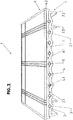
- the combination solar module generally designated 1 in the figures for example, part of a solar system and this fixed with a variety of similar modules on a suitable support base or a suitable support structure, for example, on a building roof or a local support structure.
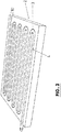
- the combined solar module 1 consists of a molded part made of a UV-resistant plastic, for example, PC, PP, LD, PE, PVC and / or PA produced carrier 2, which is rectangular in plan view.
- the carrier 2 forms an upper plate-shaped support section 2.1, a projecting beyond the bottom of this section support edge 2.2 and a plurality of parallel to the peripheral sides of the support 2 extending, also on the underside of the support section 2.1 wegumble webs 2.3, as well as the support edge 2.2 for stiffening serve the support 2 and as a support and mounting surface for the combined solar module 1.
- this support portion 2.1 a meandering, open at the top of this support portion groove 3 is formed in the adapted to receive a course of the groove 3 and thus also meandering running hose or pipe section 4 made of a corrosion-resistant material, such as plastic, eg PC , PP, LD, PE, PVC and / or PA is inserted.
- the pipe section 4 protrudes with two connection ends over the peripheral surface of the support 2 and thus also of the combination solar module, on two opposite narrow sides of the support 2 and the combination solar module.
- the support section 2.1 is further formed on its upper side so that on both sides of the groove 3 with the circular outer cross-section of the pipe section 4 adapted likewise part-circular cross-section depressions 5 are formed so that on each side of the groove 3 is a stepped transition to the top of the support portion 2.1 exists.
- the depth of the groove 3 and the outer diameter of the pipe section 4 are chosen so that the pipe section 4 is received in the groove 3 only with a part of its circumference, and with a portion of its peripheral surface but over the top of the support 2 and the support section 2.1 protrudes.
- the combi solar module 1 further comprises a closure lid 6, which consists of a UV-resistant plastic, such as PC, PP, LDPE, PVC or PA and which is produced by injection molding on the pre-assembled with the pipe section 4 support 2, in such a way in that the pipe section 4 is completely embedded in the plastic of the closure lid 6 with its peripheral region projecting over the top side of the carrier section 2.1 and the material of the closure lid 6 forms a material-locking connection at least with the top side of the carrier 2.
- the material for the closure lid 6 in adaptation to the material of the carrier 2 is selected in a suitable manner.
- the pipe section 4 is securely held in the groove 3 when forming the closure lid 6, yet the pipe section 4 is enclosed on a large part of its outer or lateral surface by the material of the closure lid 6.
- the flow channel 4.1 formed by the pipe section 4 is preferably filled with a pressure medium, for example with a gaseous and / or vaporous or liquid pressure medium, so that despite the considerable pressure applied when forming the closure cap 6, the original, complete cross section of the Pipe section 4 and the flow channel 4.1 is maintained unchanged over the entire length of this pipe section.
- the combination solar module 1 of the closure lid 6 forms after its completion a plate-shaped, with the top of the support section 2.1 flat closure cap 6.1 and a mainly on the carrier 2 remote from the top of the cap portion 6.1 protruding cap cover edge 6.2, with a for the bottom of the Cover lid section 6.2 projecting edge extension overlaps the carrier 2 at its support edge 2.1 and thereby covers the transition between the top of the support section 6.2 and the bottom of the closure lid section 6.1 to the outside.
- the FIG. 3 shows again in a perspective view of the cover provided with the cover 6 2 and the carrier consisting of the support 2 and the cover 6 supporting element 1.1 of the combination solar module. 1
- photovoltaic individual modules 8.1 are inserted on this film within the area enclosed by the closure lid edge 6.2 and are mechanically and electrically mounted in a suitable manner, so that these individual modules form a total photovoltaic module 8.
- the intermediate layer or film 7 is used inter alia. the improved heat transfer and a uniform heat distribution over the entire surface of the photovoltaic module 8.
- the required components for the electrical connection of the individual modules 8.1 to the entire module 8 and / or for the electrical connection of the combined solar module 1 with other components and / or modules and / or with the electrical installation of a solar system provided.
- the combined solar module 1 is designed so that it can be connected both electrically, and with respect to the flow channel 4.1 by flowing heat-transporting medium by simple plug or flange connections with adjacent combined solar modules and / or with an external installation. Furthermore, it is possible to provide accumulators for storing the current generated by the photovoltaic module 8 on the underside of the combination solar module 1 or of the carrier 2 and in particular also in recesses or depressions formed by the carrier edge 2.2 and the webs 2.3, preferably high-performance accumulators, e.g. Lithium batteries.
- the carrier 2 is preferably formed with not shown mounting terminals for mechanical mounting of the combination solar module 1 and / or but with foot elements, the necessary inclination of the combination with a simple installation of the combi solar modules 1 on a flat surface or only slightly inclined surface -Solar modules ensure.
- FIG. 5 shows in a simplified representation and in section an embodiment of a combination solar module 1a according to the invention, which inter alia from the carrier made as a molded plastic 2, from an applied to the carrier 2 and connected thereto, for example by gluing and / or welding, For example, laser welding connected film 9 and arranged on the film 9 photovoltaic module 8, which latter preferably again has a plurality of individual modules 8.1.
- the flow channels 4.1 are formed in the form of grooves which form a total channel or more individual channels and are sealed at the top of the carrier 2 by the film 9.
- the film 9 is elastic, so that by the pressure of guided in the flow channels 4.1 liquid heat transporting medium (preferably water, optionally with antifreeze additives) formed by the film wall 9 of each flow channel 4.1 tight against the carrier 2 facing bottom of the photovoltaic module 8 or the individual modules 8.1 pressed pressed.
- liquid heat transporting medium preferably water, optionally with antifreeze additives
- an optimal heat transfer between the heat-transporting medium in Flow channels 4.1 and the photovoltaic module 8 ensures, even if the carrier 2 is not completely flat on its the flow channels 4.1 and the corresponding grooves having top.
- the combination solar module 1a it may be expedient to provide on the underside a stiffening support plate 10 or a corresponding frame made of a metallic material, on which or on which then the combination solar module 1a foot-like fasteners 11 at a distance from a substrate 12, for example, can be attached to the outer surface of a building roof.
- sprinkler nozzles are referred to, which are provided on the mounting surface 12, for example, the building roof facing bottom of the combination solar module and from which then in a possible fire serving as a heat-transporting medium water is discharged as extinguishing water automatically on the mounting surface 12.
- These sprinkler nozzles 13 can be provided without additional effort, especially since water is used as a heat-transporting medium anyway and the corresponding connections to the combi solar modules 1a for supplying the heat-transporting medium are present and can be easily connected via lines 14 to the sprinkler nozzles 13 ,
- a sensor 15 is designated, which is also provided on the underside of the combination solar module 1a and in the event of fire, an electrical control signal, for example, to activate the sprinkler nozzles 13 or the sprinkler nozzles to the inlet of the heat-transporting medium subsequent valve and / or Triggering of a corresponding alarm.
- the signal of the sensor 15 is preferably also used to increase the delivery rate of a pump located in the flow for the heat transporting pump in case of fire.
- a frame which leaves at least the greater part of the surface of the underside of the carrier 2, and the flow channels 4.1 can be used in the event of fire for discharging serving as the extinguishing medium heat transfer medium, and thereby in that the carrier 2 melts due to the action of heat, thereby opening the flow channels 4.1 towards the attachment surface 12.
- the combined solar modules 1 and 1a or their photovoltaic modules 8 are connected in the usual way to the external electrical installation.
- the heat-transporting medium for example of water with antifreeze additives, flowed through flow channels 4.1 of the solar system forming combi solar modules 1 and 1a, for example, connected in series with each other to a heat pump or to another system connected, which allows use of the heat-transporting medium contained heat energy and / or heating of the heat-transporting medium.
- the combination solar module 1 or 1a or the solar systems produced with a plurality of such modules offer considerable advantages.
- the photovoltaic modules 8 in intense sunlight, especially in the summer months, ie in terms of generating the electric current main yield times, by the flow channels 4.1 flowing through heat-transporting medium to cool and thereby increase the efficiency of the photovoltaic modules 8 .
- the corresponding temperature coefficient is for example -0.5% / ° C, which means that a photovoltaic module, which reaches a rated power of 200 W at 25 ° C, at a temperature of 90 ° only provides a power of 135W, i.
- the temperature of the photovoltaic module 8 can be maintained at a required for optimal current efficiency temperature by cooling even at high ambient temperatures.
- the dissipated with the heat transfer medium heat energy is used, for example, for heating domestic water, and / or stored.
- the heat transfer medium flowing through the flow channels 4.1 will be used to heat the photovoltaic modules 8, for example, to remove by defrosting an ice formation on the module outer surface and / or snow present there which impairs the efficiency of these modules.
- Additional advantages of the combination solar module 1a include u.a. It is improved by the use of the film 9 between the support 2 and the photovoltaic module 8, the heat transfer between the heat-transporting medium and the photovoltaic module 8 that the film 9 has only a small thickness, which anyway the heat transfer to the photovoltaic module 8 is improved , Furthermore, results from the film 9, a further simplification of the combined solar module 1a in terms of design and manufacturing technology. Another advantage of the combination solar module 1a is a further reduction of the total weight, namely the fact that instead of the closure cap 6, the film 9 is used.
Landscapes
- Engineering & Computer Science (AREA)
- Physics & Mathematics (AREA)
- Life Sciences & Earth Sciences (AREA)
- Sustainable Development (AREA)
- Sustainable Energy (AREA)
- Thermal Sciences (AREA)
- Chemical & Material Sciences (AREA)
- Combustion & Propulsion (AREA)
- Mechanical Engineering (AREA)
- General Engineering & Computer Science (AREA)
- Photovoltaic Devices (AREA)
- Roof Covering Using Slabs Or Stiff Sheets (AREA)
Claims (6)
- Module solaire combiné comprenant un élément de base ou de support (1.1) plat, en forme de plaque ou essentiellement en forme de plaque, comprenant au moins un canal d'écoulement (4.1) formé dans l'élément de base ou de support (1.1) pour un fluide transportant de la chaleur ainsi qu'au moins un module photovoltaïque (8, 8.1) sur une face supérieure de l'élément de base ou de support (1.1), dans lequel l'élément de base ou de support (1.1) est fabriqué en plastique et est composé d'un support (2) fabriqué en plastique en tant que pièce moulée ainsi que d'un élément de fermeture formant la face supérieure de l'élément de base ou de support (1.1), dans lequel l'au moins un canal d'écoulement (4.1) est formé entre le support (2) et l'élément de fermeture, caractérisé en ce que l'élément de fermeture est un film plastique élastique (9), dans lequel le film plastique élastique formant l'élément de fermeture est relié au support (2) au moins le long de l'au moins un canal d'écoulement (4.1), dans lequel dans le support (2) fabriqué en plastique en tant que pièce moulée, les canaux d'écoulement (4.1) sont formés sous forme de rainures et forment un canal global ou plusieurs canaux individuels et sont fermés de manière étanche par le film plastique élastique (9) sur la face supérieure du support (2).
- Module solaire combiné selon la revendication 1, caractérisé en ce que le support (2) et le film plastique (9) sont composés d'un plastique résistant aux UV, en particulier en PC, PP, LDPE, PVC et/ou PA.
- Module solaire combiné selon l'une des revendications précédentes, caractérisé en ce que des raccords pour relier le module solaire combiné (1) à une installation extérieure et/ou à des modules solaires combinés voisins sont prévus sur l'élément de base ou de support (1.1), dans lequel ces raccords sont produits et/ou moulés de préférence au moins partiellement par moulage par injection.
- Module solaire combiné selon l'une des revendications précédentes, caractérisé en ce que le support (2) est formé d'une seule pièce avec au moins un bord de renfort (6.2, 2.2) et/ou avec des nervures de renfort (2.3) et/ou avec des éléments de fixation.
- Module solaire combiné selon l'une des revendications précédentes, caractérisé en ce qu'une couche ou un film (7) dans un matériau à conductivité thermique élevée est placé(e) entre l'au moins un module photovoltaïque (8, 8.1) et le film plastique (9).
- Module solaire combiné selon l'une des revendications précédentes, caractérisé en ce que le film plastique (9) est collé ou soudé au support (2) au moins le long de l'au moins un canal d'écoulement (4.1).
Priority Applications (1)
| Application Number | Priority Date | Filing Date | Title |
|---|---|---|---|
| HRP20180117TT HRP20180117T1 (hr) | 2011-07-06 | 2018-01-22 | Kombinirani solarni modul |
Applications Claiming Priority (1)
| Application Number | Priority Date | Filing Date | Title |
|---|---|---|---|
| DE102011107302 | 2011-07-06 |
Publications (2)
| Publication Number | Publication Date |
|---|---|
| EP2544246A1 EP2544246A1 (fr) | 2013-01-09 |
| EP2544246B1 true EP2544246B1 (fr) | 2017-12-20 |
Family
ID=46514102
Family Applications (1)
| Application Number | Title | Priority Date | Filing Date |
|---|---|---|---|
| EP12174351.2A Active EP2544246B1 (fr) | 2011-07-06 | 2012-06-29 | Module solaire combiné |
Country Status (6)
| Country | Link |
|---|---|
| EP (1) | EP2544246B1 (fr) |
| DE (1) | DE102012105755A1 (fr) |
| ES (1) | ES2656552T3 (fr) |
| HR (1) | HRP20180117T1 (fr) |
| HU (1) | HUE036371T2 (fr) |
| PT (1) | PT2544246T (fr) |
Families Citing this family (2)
| Publication number | Priority date | Publication date | Assignee | Title |
|---|---|---|---|---|
| CN104567021A (zh) * | 2013-10-25 | 2015-04-29 | 南京安达泰星电子有限公司 | 太阳能集热器 |
| PT107491B (pt) * | 2014-02-28 | 2018-01-11 | Univ Do Algarve | Colector termoeléctrico equipado com um sistema multi-tubagens e canal transparentes |
Family Cites Families (5)
| Publication number | Priority date | Publication date | Assignee | Title |
|---|---|---|---|---|
| DE2523089A1 (de) * | 1975-05-24 | 1976-12-02 | Messer Griesheim Gmbh | Kollektor fuer sonnenwaerme |
| DE2626958B1 (de) * | 1976-06-16 | 1977-03-31 | Hans Viessmann | Sonnenkollektor |
| US20090044798A1 (en) * | 2007-08-14 | 2009-02-19 | Chen Shih H | Coilable solar water heater |
| US20100314081A1 (en) * | 2009-06-12 | 2010-12-16 | Reis Bradley E | High Temperature Graphite Heat Exchanger |
| EP2284910B1 (fr) * | 2009-08-12 | 2016-03-02 | Roth Werke GmbH | Absorbeur solaire |
-
2012
- 2012-06-29 PT PT121743512T patent/PT2544246T/pt unknown
- 2012-06-29 DE DE102012105755A patent/DE102012105755A1/de not_active Withdrawn
- 2012-06-29 HU HUE12174351A patent/HUE036371T2/hu unknown
- 2012-06-29 EP EP12174351.2A patent/EP2544246B1/fr active Active
- 2012-06-29 ES ES12174351.2T patent/ES2656552T3/es active Active
-
2018
- 2018-01-22 HR HRP20180117TT patent/HRP20180117T1/hr unknown
Non-Patent Citations (1)
| Title |
|---|
| None * |
Also Published As
| Publication number | Publication date |
|---|---|
| DE102012105755A1 (de) | 2013-01-10 |
| HRP20180117T1 (hr) | 2018-07-13 |
| HUE036371T2 (hu) | 2018-07-30 |
| ES2656552T3 (es) | 2018-02-27 |
| PT2544246T (pt) | 2018-03-07 |
| EP2544246A1 (fr) | 2013-01-09 |
Similar Documents
| Publication | Publication Date | Title |
|---|---|---|
| EP2033231B1 (fr) | Élément solaire avec dispositif de régulation de température | |
| EP2686633B1 (fr) | Accumulateur de chaleur latente et système de stockage d'energie avec un tel accumulateur | |
| EP2694885B1 (fr) | Dispositif et procédé de conversion d'énergie solaire rayonnante en courant électrique et/ou chaleur | |
| DE102006009194A1 (de) | Anordnung aus einer tragenden Gebäudestruktur und einem Solarzellenaufbau | |
| WO2010040525A2 (fr) | Dispositif pour absorber un rayonnement électromagnétique | |
| WO2008067808A2 (fr) | Module solaire électrothermique | |
| EP2544246B1 (fr) | Module solaire combiné | |
| DE102008048547A1 (de) | Dachdeckungsmodul | |
| DE102011055311A1 (de) | Verfahren zur Herstellung von Wärmetauscherkörpern und Wärmetauscherkörper für plattenförmige Solarmodule | |
| CH707930B1 (de) | Fassaden- oder Dachelement, aufweisend eine oder mehrere photovoltaische Solarzellen. | |
| DE102010027046A1 (de) | Gebäudeaußenelement | |
| WO2013000713A2 (fr) | Installation solaire dotée d'un collecteur solaire et d'un convertisseur photovoltaïque ou thermoélectrique | |
| DE102010008600A1 (de) | Gebäudeaußenelement | |
| DE102013000135A1 (de) | Selbsttragendes Fassaden- oder Dachelement und damit hergestelltes Fassaden- oder Dachbekleidungssystem | |
| WO2001069689A1 (fr) | Element a energie avec couche photovoltaique | |
| DE102008036738B4 (de) | Folien-Flachkollektor | |
| EP2567410B1 (fr) | Collecteur hybride | |
| DE202016003756U1 (de) | Photovoltaik-Modul mit Wärmetauscher für Solarstrahlungs- und Luft-Wärme | |
| DE102011101212A1 (de) | Dach- und Fassaden-Leichtbauelement | |
| EP2866345B1 (fr) | Panneau photovoltaïque avec élément de chauffage de surface | |
| DE102011115018A1 (de) | Sonnenkollektoren, Heizkörper, Kühlkörper | |
| EP2026016A2 (fr) | Tuile | |
| DE102008050833A1 (de) | Klimatisierungssystem zur Anbringung auf einem Dach | |
| DE202011100503U1 (de) | Dach- und Fassaden-Leichtbauelement | |
| EP1347113A1 (fr) | Elément préfabriqué de construction avec module integré de cellules solaires |
Legal Events
| Date | Code | Title | Description |
|---|---|---|---|
| PUAI | Public reference made under article 153(3) epc to a published international application that has entered the european phase |
Free format text: ORIGINAL CODE: 0009012 |
|
| AK | Designated contracting states |
Kind code of ref document: A1 Designated state(s): AL AT BE BG CH CY CZ DE DK EE ES FI FR GB GR HR HU IE IS IT LI LT LU LV MC MK MT NL NO PL PT RO RS SE SI SK SM TR |
|
| AX | Request for extension of the european patent |
Extension state: BA ME |
|
| 17P | Request for examination filed |
Effective date: 20130702 |
|
| RBV | Designated contracting states (corrected) |
Designated state(s): AL AT BE BG CH CY CZ DE DK EE ES FI FR GB GR HR HU IE IS IT LI LT LU LV MC MK MT NL NO PL PT RO RS SE SI SK SM TR |
|
| 17Q | First examination report despatched |
Effective date: 20160504 |
|
| STAA | Information on the status of an ep patent application or granted ep patent |
Free format text: STATUS: EXAMINATION IS IN PROGRESS |
|
| REG | Reference to a national code |
Ref country code: DE Ref legal event code: R079 Ref document number: 502012011849 Country of ref document: DE Free format text: PREVIOUS MAIN CLASS: H01L0031058000 Ipc: H02S0040440000 |
|
| RIC1 | Information provided on ipc code assigned before grant |
Ipc: H02S 40/44 20140101AFI20170628BHEP |
|
| GRAP | Despatch of communication of intention to grant a patent |
Free format text: ORIGINAL CODE: EPIDOSNIGR1 |
|
| STAA | Information on the status of an ep patent application or granted ep patent |
Free format text: STATUS: GRANT OF PATENT IS INTENDED |
|
| INTG | Intention to grant announced |
Effective date: 20170817 |
|
| GRAS | Grant fee paid |
Free format text: ORIGINAL CODE: EPIDOSNIGR3 |
|
| GRAA | (expected) grant |
Free format text: ORIGINAL CODE: 0009210 |
|
| STAA | Information on the status of an ep patent application or granted ep patent |
Free format text: STATUS: THE PATENT HAS BEEN GRANTED |
|
| AK | Designated contracting states |
Kind code of ref document: B1 Designated state(s): AL AT BE BG CH CY CZ DE DK EE ES FI FR GB GR HR HU IE IS IT LI LT LU LV MC MK MT NL NO PL PT RO RS SE SI SK SM TR |
|
| REG | Reference to a national code |
Ref country code: GB Ref legal event code: FG4D Free format text: NOT ENGLISH |
|
| REG | Reference to a national code |
Ref country code: CH Ref legal event code: EP |
|
| REG | Reference to a national code |
Ref country code: IE Ref legal event code: FG4D Free format text: LANGUAGE OF EP DOCUMENT: GERMAN |
|
| REG | Reference to a national code |
Ref country code: AT Ref legal event code: REF Ref document number: 957238 Country of ref document: AT Kind code of ref document: T Effective date: 20180115 |
|
| REG | Reference to a national code |
Ref country code: DE Ref legal event code: R096 Ref document number: 502012011849 Country of ref document: DE |
|
| REG | Reference to a national code |
Ref country code: HR Ref legal event code: TUEP Ref document number: P20180117 Country of ref document: HR |
|
| REG | Reference to a national code |
Ref country code: RO Ref legal event code: EPE |
|
| REG | Reference to a national code |
Ref country code: ES Ref legal event code: FG2A Ref document number: 2656552 Country of ref document: ES Kind code of ref document: T3 Effective date: 20180227 |
|
| REG | Reference to a national code |
Ref country code: PT Ref legal event code: SC4A Ref document number: 2544246 Country of ref document: PT Date of ref document: 20180307 Kind code of ref document: T Free format text: AVAILABILITY OF NATIONAL TRANSLATION Effective date: 20180228 |
|
| REG | Reference to a national code |
Ref country code: CH Ref legal event code: NV Representative=s name: MICHELI AND CIE SA, CH |
|
| REG | Reference to a national code |
Ref country code: NL Ref legal event code: MP Effective date: 20171220 |
|
| PG25 | Lapsed in a contracting state [announced via postgrant information from national office to epo] |
Ref country code: NO Free format text: LAPSE BECAUSE OF FAILURE TO SUBMIT A TRANSLATION OF THE DESCRIPTION OR TO PAY THE FEE WITHIN THE PRESCRIBED TIME-LIMIT Effective date: 20180320 Ref country code: LT Free format text: LAPSE BECAUSE OF FAILURE TO SUBMIT A TRANSLATION OF THE DESCRIPTION OR TO PAY THE FEE WITHIN THE PRESCRIBED TIME-LIMIT Effective date: 20171220 Ref country code: FI Free format text: LAPSE BECAUSE OF FAILURE TO SUBMIT A TRANSLATION OF THE DESCRIPTION OR TO PAY THE FEE WITHIN THE PRESCRIBED TIME-LIMIT Effective date: 20171220 Ref country code: SE Free format text: LAPSE BECAUSE OF FAILURE TO SUBMIT A TRANSLATION OF THE DESCRIPTION OR TO PAY THE FEE WITHIN THE PRESCRIBED TIME-LIMIT Effective date: 20171220 |
|
| REG | Reference to a national code |
Ref country code: LT Ref legal event code: MG4D |
|
| PG25 | Lapsed in a contracting state [announced via postgrant information from national office to epo] |
Ref country code: LV Free format text: LAPSE BECAUSE OF FAILURE TO SUBMIT A TRANSLATION OF THE DESCRIPTION OR TO PAY THE FEE WITHIN THE PRESCRIBED TIME-LIMIT Effective date: 20171220 |
|
| REG | Reference to a national code |
Ref country code: HR Ref legal event code: NPPZ Ref document number: P20180117 Country of ref document: HR |
|
| REG | Reference to a national code |
Ref country code: HR Ref legal event code: NPPU Ref document number: P20180117 Country of ref document: HR |
|
| REG | Reference to a national code |
Ref country code: FR Ref legal event code: PLFP Year of fee payment: 7 |
|
| PG25 | Lapsed in a contracting state [announced via postgrant information from national office to epo] |
Ref country code: NL Free format text: LAPSE BECAUSE OF FAILURE TO SUBMIT A TRANSLATION OF THE DESCRIPTION OR TO PAY THE FEE WITHIN THE PRESCRIBED TIME-LIMIT Effective date: 20171220 |
|
| REG | Reference to a national code |
Ref country code: GR Ref legal event code: EP Ref document number: 20180400509 Country of ref document: GR Effective date: 20180627 |
|
| REG | Reference to a national code |
Ref country code: HR Ref legal event code: T1PR Ref document number: P20180117 Country of ref document: HR |
|
| REG | Reference to a national code |
Ref country code: HU Ref legal event code: AG4A Ref document number: E036371 Country of ref document: HU |
|
| PG25 | Lapsed in a contracting state [announced via postgrant information from national office to epo] |
Ref country code: CY Free format text: LAPSE BECAUSE OF FAILURE TO SUBMIT A TRANSLATION OF THE DESCRIPTION OR TO PAY THE FEE WITHIN THE PRESCRIBED TIME-LIMIT Effective date: 20171220 Ref country code: EE Free format text: LAPSE BECAUSE OF FAILURE TO SUBMIT A TRANSLATION OF THE DESCRIPTION OR TO PAY THE FEE WITHIN THE PRESCRIBED TIME-LIMIT Effective date: 20171220 Ref country code: CZ Free format text: LAPSE BECAUSE OF FAILURE TO SUBMIT A TRANSLATION OF THE DESCRIPTION OR TO PAY THE FEE WITHIN THE PRESCRIBED TIME-LIMIT Effective date: 20171220 Ref country code: SK Free format text: LAPSE BECAUSE OF FAILURE TO SUBMIT A TRANSLATION OF THE DESCRIPTION OR TO PAY THE FEE WITHIN THE PRESCRIBED TIME-LIMIT Effective date: 20171220 |
|
| PG25 | Lapsed in a contracting state [announced via postgrant information from national office to epo] |
Ref country code: PL Free format text: LAPSE BECAUSE OF FAILURE TO SUBMIT A TRANSLATION OF THE DESCRIPTION OR TO PAY THE FEE WITHIN THE PRESCRIBED TIME-LIMIT Effective date: 20171220 Ref country code: SM Free format text: LAPSE BECAUSE OF FAILURE TO SUBMIT A TRANSLATION OF THE DESCRIPTION OR TO PAY THE FEE WITHIN THE PRESCRIBED TIME-LIMIT Effective date: 20171220 Ref country code: IS Free format text: LAPSE BECAUSE OF FAILURE TO SUBMIT A TRANSLATION OF THE DESCRIPTION OR TO PAY THE FEE WITHIN THE PRESCRIBED TIME-LIMIT Effective date: 20180420 |
|
| REG | Reference to a national code |
Ref country code: DE Ref legal event code: R097 Ref document number: 502012011849 Country of ref document: DE |
|
| PG25 | Lapsed in a contracting state [announced via postgrant information from national office to epo] |
Ref country code: MT Free format text: LAPSE BECAUSE OF FAILURE TO SUBMIT A TRANSLATION OF THE DESCRIPTION OR TO PAY THE FEE WITHIN THE PRESCRIBED TIME-LIMIT Effective date: 20171220 |
|
| PLBE | No opposition filed within time limit |
Free format text: ORIGINAL CODE: 0009261 |
|
| STAA | Information on the status of an ep patent application or granted ep patent |
Free format text: STATUS: NO OPPOSITION FILED WITHIN TIME LIMIT |
|
| 26N | No opposition filed |
Effective date: 20180921 |
|
| PG25 | Lapsed in a contracting state [announced via postgrant information from national office to epo] |
Ref country code: DK Free format text: LAPSE BECAUSE OF FAILURE TO SUBMIT A TRANSLATION OF THE DESCRIPTION OR TO PAY THE FEE WITHIN THE PRESCRIBED TIME-LIMIT Effective date: 20171220 |
|
| PG25 | Lapsed in a contracting state [announced via postgrant information from national office to epo] |
Ref country code: RS Free format text: LAPSE BECAUSE OF NON-PAYMENT OF DUE FEES Effective date: 20181026 Ref country code: RO Free format text: LAPSE BECAUSE OF NON-PAYMENT OF DUE FEES Effective date: 20171220 |
|
| REG | Reference to a national code |
Ref country code: CH Ref legal event code: PL |
|
| GBPC | Gb: european patent ceased through non-payment of renewal fee |
Effective date: 20180629 |
|
| PG25 | Lapsed in a contracting state [announced via postgrant information from national office to epo] |
Ref country code: SI Free format text: LAPSE BECAUSE OF FAILURE TO SUBMIT A TRANSLATION OF THE DESCRIPTION OR TO PAY THE FEE WITHIN THE PRESCRIBED TIME-LIMIT Effective date: 20171220 |
|
| REG | Reference to a national code |
Ref country code: BE Ref legal event code: MM Effective date: 20180630 |
|
| PG25 | Lapsed in a contracting state [announced via postgrant information from national office to epo] |
Ref country code: MC Free format text: LAPSE BECAUSE OF FAILURE TO SUBMIT A TRANSLATION OF THE DESCRIPTION OR TO PAY THE FEE WITHIN THE PRESCRIBED TIME-LIMIT Effective date: 20171220 Ref country code: LU Free format text: LAPSE BECAUSE OF NON-PAYMENT OF DUE FEES Effective date: 20180629 |
|
| REG | Reference to a national code |
Ref country code: IE Ref legal event code: MM4A |
|
| PG25 | Lapsed in a contracting state [announced via postgrant information from national office to epo] |
Ref country code: IE Free format text: LAPSE BECAUSE OF NON-PAYMENT OF DUE FEES Effective date: 20180629 Ref country code: GB Free format text: LAPSE BECAUSE OF NON-PAYMENT OF DUE FEES Effective date: 20180629 Ref country code: CH Free format text: LAPSE BECAUSE OF NON-PAYMENT OF DUE FEES Effective date: 20180630 Ref country code: HU Free format text: LAPSE BECAUSE OF NON-PAYMENT OF DUE FEES Effective date: 20180630 Ref country code: LI Free format text: LAPSE BECAUSE OF NON-PAYMENT OF DUE FEES Effective date: 20180630 |
|
| PG25 | Lapsed in a contracting state [announced via postgrant information from national office to epo] |
Ref country code: BE Free format text: LAPSE BECAUSE OF NON-PAYMENT OF DUE FEES Effective date: 20180630 |
|
| REG | Reference to a national code |
Ref country code: HR Ref legal event code: ODRP Ref document number: P20180117 Country of ref document: HR Payment date: 20190614 Year of fee payment: 8 |
|
| PGFP | Annual fee paid to national office [announced via postgrant information from national office to epo] |
Ref country code: SI Payment date: 20190603 Year of fee payment: 8 |
|
| PGFP | Annual fee paid to national office [announced via postgrant information from national office to epo] |
Ref country code: AT Payment date: 20190621 Year of fee payment: 8 |
|
| PG25 | Lapsed in a contracting state [announced via postgrant information from national office to epo] |
Ref country code: AL Free format text: LAPSE BECAUSE OF FAILURE TO SUBMIT A TRANSLATION OF THE DESCRIPTION OR TO PAY THE FEE WITHIN THE PRESCRIBED TIME-LIMIT Effective date: 20171220 |
|
| REG | Reference to a national code |
Ref country code: HR Ref legal event code: PBON Ref document number: P20180117 Country of ref document: HR Effective date: 20200629 |
|
| REG | Reference to a national code |
Ref country code: AT Ref legal event code: MM01 Ref document number: 957238 Country of ref document: AT Kind code of ref document: T Effective date: 20200629 |
|
| PG25 | Lapsed in a contracting state [announced via postgrant information from national office to epo] |
Ref country code: GR Free format text: LAPSE BECAUSE OF NON-PAYMENT OF DUE FEES Effective date: 20210111 |
|
| PG25 | Lapsed in a contracting state [announced via postgrant information from national office to epo] |
Ref country code: AT Free format text: LAPSE BECAUSE OF NON-PAYMENT OF DUE FEES Effective date: 20200629 |
|
| PG25 | Lapsed in a contracting state [announced via postgrant information from national office to epo] |
Ref country code: HR Free format text: LAPSE BECAUSE OF NON-PAYMENT OF DUE FEES Effective date: 20200629 |
|
| PGFP | Annual fee paid to national office [announced via postgrant information from national office to epo] |
Ref country code: PT Payment date: 20220617 Year of fee payment: 11 Ref country code: IT Payment date: 20220627 Year of fee payment: 11 Ref country code: BG Payment date: 20220621 Year of fee payment: 11 |
|
| PGFP | Annual fee paid to national office [announced via postgrant information from national office to epo] |
Ref country code: TR Payment date: 20220627 Year of fee payment: 11 |
|
| PGFP | Annual fee paid to national office [announced via postgrant information from national office to epo] |
Ref country code: FR Payment date: 20220628 Year of fee payment: 11 |
|
| PGFP | Annual fee paid to national office [announced via postgrant information from national office to epo] |
Ref country code: ES Payment date: 20220829 Year of fee payment: 11 Ref country code: DE Payment date: 20220630 Year of fee payment: 11 |
|
| REG | Reference to a national code |
Ref country code: DE Ref legal event code: R119 Ref document number: 502012011849 Country of ref document: DE |
|
| PG25 | Lapsed in a contracting state [announced via postgrant information from national office to epo] |
Ref country code: DE Free format text: LAPSE BECAUSE OF NON-PAYMENT OF DUE FEES Effective date: 20240103 |
|
| PG25 | Lapsed in a contracting state [announced via postgrant information from national office to epo] |
Ref country code: FR Free format text: LAPSE BECAUSE OF NON-PAYMENT OF DUE FEES Effective date: 20230630 |
|
| PG25 | Lapsed in a contracting state [announced via postgrant information from national office to epo] |
Ref country code: IT Free format text: LAPSE BECAUSE OF NON-PAYMENT OF DUE FEES Effective date: 20230629 |
|
| REG | Reference to a national code |
Ref country code: ES Ref legal event code: FD2A Effective date: 20240802 |
|
| PG25 | Lapsed in a contracting state [announced via postgrant information from national office to epo] |
Ref country code: ES Free format text: LAPSE BECAUSE OF NON-PAYMENT OF DUE FEES Effective date: 20230630 |
|
| PG25 | Lapsed in a contracting state [announced via postgrant information from national office to epo] |
Ref country code: ES Free format text: LAPSE BECAUSE OF NON-PAYMENT OF DUE FEES Effective date: 20230630 |
|
| PG25 | Lapsed in a contracting state [announced via postgrant information from national office to epo] |
Ref country code: BG Free format text: LAPSE BECAUSE OF NON-PAYMENT OF DUE FEES Effective date: 20230629 |
|
| PG25 | Lapsed in a contracting state [announced via postgrant information from national office to epo] |
Ref country code: BG Free format text: LAPSE BECAUSE OF NON-PAYMENT OF DUE FEES Effective date: 20230629 |
|
| PG25 | Lapsed in a contracting state [announced via postgrant information from national office to epo] |
Ref country code: PT Free format text: LAPSE BECAUSE OF NON-PAYMENT OF DUE FEES Effective date: 20230629 |